
Manual
Page 5
Chapter 3 Drivers Installation 45 3-1 Install Chipset Drivers 45 3-2 SoftwareApplication 46 3-3 Software Information 46 3-4 Hardware Information 47 3-5 Contact Us ...47 Chapter 4 Appendix 49 4-1 Unique Software Utilities 49 4-1-1 EasyTune 5 Introduction 49 4-1-2 Xpress Recovery2 Introduction 50 4-1-3 Flash BIOS Method Introduction 52 4-1-4 Configuring SATA Hard Drive(s 61 4-1-5 2 / 4 / 6 Channel Audio Function Introduction 73 4-2 Troubleshooting 78 - 5 -
Chapter 3 Drivers Installation 45 3-1 Install Chipset Drivers 45 3-2 SoftwareApplication 46 3-3 Software Information 46 3-4 Hardware Information 47 3-5 Contact Us ...47 Chapter 4 Appendix 49 4-1 Unique Software Utilities 49 4-1-1 EasyTune 5 Introduction 49 4-1-2 Xpress Recovery2 Introduction 50 4-1-3 Flash BIOS Method Introduction 52 4-1-4 Configuring SATA Hard Drive(s 61 4-1-5 2 / 4 / 6 Channel Audio Function Introduction 73 4-2 Troubleshooting 78 - 5 -
Manual
Page 16
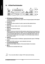
GA-VM800PMC Motherboard - 16 - If your OS or device(s) vendors. can use audio software to configure 2-/4-/6- You can be connected to Line In jack. Parallel Port The parallel port allows connection of 10/100 Mbps. VGA Port Monitor ... to MIC In jack. For more information please contact your OS does not support USB controller, please contact OS vendor for possible patch or driver upgrade. channel audio functioning. Line In Devices like mouses, modems, and etc. MIC In Microphone can be connected to VGA port. Serial Port Devices like CD-ROM...
GA-VM800PMC Motherboard - 16 - If your OS or device(s) vendors. can use audio software to configure 2-/4-/6- You can be connected to Line In jack. Parallel Port The parallel port allows connection of 10/100 Mbps. VGA Port Monitor ... to MIC In jack. For more information please contact your OS does not support USB controller, please contact OS vendor for possible patch or driver upgrade. channel audio functioning. Line In Devices like mouses, modems, and etc. MIC In Microphone can be connected to VGA port. Serial Port Devices like CD-ROM...
Manual
Page 73
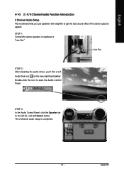
... STEP 2: After installing the audio driver, you use speakers with amplifier to get the best sound effect if the stereo output is completed. - 73 - In the left list, click 2 Channel button. STEP 1: Connect the stereo speakers or earphone to open the Audio Control Panel. English 4-1-5 2 / 4 / 6 Channel Audio Function Introduction 2 Channel Audio Setup We recommend that...
... STEP 2: After installing the audio driver, you use speakers with amplifier to get the best sound effect if the stereo output is completed. - 73 - In the left list, click 2 Channel button. STEP 1: Connect the stereo speakers or earphone to open the Audio Control Panel. English 4-1-5 2 / 4 / 6 Channel Audio Function Introduction 2 Channel Audio Setup We recommend that...
Manual
Page 74
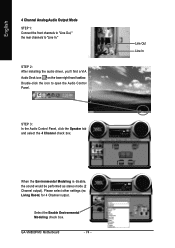
... box. STEP 2: After installing the audio driver, you'll find a VIA Audio Deck icon on the lower right hand taskbar. Line Out Line In When the Environmental Modeling is disable, the sound would be performed as stereo mode (2 Channel output). GA-VM800PMC Motherboard - 74 - Double-click the... icon to "Line In." English 4 Channel Analog Audio Output Mode STEP 1: Connect the front channels to "Line Out," the rear channels to open ...
... box. STEP 2: After installing the audio driver, you'll find a VIA Audio Deck icon on the lower right hand taskbar. Line Out Line In When the Environmental Modeling is disable, the sound would be performed as stereo mode (2 Channel output). GA-VM800PMC Motherboard - 74 - Double-click the... icon to "Line In." English 4 Channel Analog Audio Output Mode STEP 1: Connect the front channels to "Line Out," the rear channels to open ...
Manual
Page 75
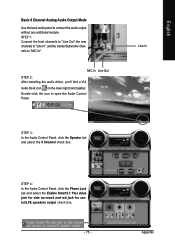
...front channels to "Line Out",the rear channels to "Line In", and the Center/Subwoofer channels to connect the audio output without any additional module. Line In STEP 3: In the Audio Control Panel, click the Speaker tab and select the 6 Channel check box. Appendix Double-click the icon to ...the Audio Control Panel. STEP 4: In the Audio Control Panel, click the Phone Jack tab and select the Enable Smart5.1 Plus (blue jack for side surround and red jack for center/LFE speakers output check box. - 75 - MIC In Line Out STEP 2: After installing the audio driver, you'll find a VIA Audio Deck...
...front channels to "Line Out",the rear channels to "Line In", and the Center/Subwoofer channels to connect the audio output without any additional module. Line In STEP 3: In the Audio Control Panel, click the Speaker tab and select the 6 Channel check box. Appendix Double-click the icon to ...the Audio Control Panel. STEP 4: In the Audio Control Panel, click the Phone Jack tab and select the Enable Smart5.1 Plus (blue jack for side surround and red jack for center/LFE speakers output check box. - 75 - MIC In Line Out STEP 2: After installing the audio driver, you'll find a VIA Audio Deck...
Manual
Page 77
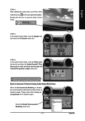
... Modeling is disable, the sound would be performed as stereo mode (2 Channel output). Select the Enable Environmental Modeling check box. - 77 - STEP 6: In the Audio Control Panel, click the Phone Jack tab and do not select the Enable Smart5.1 Plus (blue jack for side surround and red jack for 6 Channel... the 6 Channel check box. Please select other settings (ex: Living Room) for center/LFE speakers output check box. Appendix English STEP 4: After installing the audio driver, you'll find a SVIA Audio Deck icon on the lower right hand taskbar. Double-click the icon to open the...
... Modeling is disable, the sound would be performed as stereo mode (2 Channel output). Select the Enable Environmental Modeling check box. - 77 - STEP 6: In the Audio Control Panel, click the Phone Jack tab and do not select the Enable Smart5.1 Plus (blue jack for side surround and red jack for 6 Channel... the 6 Channel check box. Please select other settings (ex: Living Room) for center/LFE speakers output check box. Appendix English STEP 4: After installing the audio driver, you'll find a SVIA Audio Deck icon on the lower right hand taskbar. Double-click the icon to open the...


