
Manual
Page 1
GA-Q35M-S2 LGA775 socket motherboard for Intel® CoreTM processor family/ Intel® Pentium® processor family/Intel® Celeron® processor family User's Manual Rev. 1001 12ME-Q35MS2-1001R
GA-Q35M-S2 LGA775 socket motherboard for Intel® CoreTM processor family/ Intel® Pentium® processor family/Intel® Celeron® processor family User's Manual Rev. 1001 12ME-Q35MS2-1001R

Manual
Page 2
Motherboard GA-Q35M-S2 Nov. 21, 2007 Motherboard GA-Q35M-S2 Nov. 21, 2007
Motherboard GA-Q35M-S2 Nov. 21, 2007 Motherboard GA-Q35M-S2 Nov. 21, 2007

Manual
Page 3
...on how to the specifications and features in this manual may be made by GIGABYTE without GIGABYTE's prior written permission. Check your motherboard looks like this product, GIGABYTE provides the following types of GIGABYTE branded motherboards. Changes to use of this : "REV: X.X." is 1.0. sive global... information, check on our website at: http://www.gigabyte.com.tw Identifying Your Motherboard Revision The revision number on our website. Example: For example, "REV: 1.0" means the revision of the motherboard is designated by GIGA-BYTE TECHNOLOGY CO., LTD. ...
...on how to the specifications and features in this manual may be made by GIGABYTE without GIGABYTE's prior written permission. Check your motherboard looks like this product, GIGABYTE provides the following types of GIGABYTE branded motherboards. Changes to use of this : "REV: X.X." is 1.0. sive global... information, check on our website at: http://www.gigabyte.com.tw Identifying Your Motherboard Revision The revision number on our website. Example: For example, "REV: 1.0" means the revision of the motherboard is designated by GIGA-BYTE TECHNOLOGY CO., LTD. ...

Manual
Page 4
Table of Contents OptionalItems ...6 Box Contents ...6 GA-Q35M-S2 Motherboard Layout 7 Block Diagram ...8 Chapter 1 Hardware Installation 9 1-1 Installation Precautions 9 1-2 Product Specifications 10 1-3 Installing the CPU and CPU Cooler 13 1-3-1 Installing the CPU 13 1-3-2 Installing the CPU ...
Table of Contents OptionalItems ...6 Box Contents ...6 GA-Q35M-S2 Motherboard Layout 7 Block Diagram ...8 Chapter 1 Hardware Installation 9 1-1 Installation Precautions 9 1-2 Product Specifications 10 1-3 Installing the CPU and CPU Cooler 13 1-3-1 Installing the CPU 13 1-3-2 Installing the CPU ...

Manual
Page 6
... and out cable (Part No. 12CR1-1SPINO-11R) COM port cable (Part No. 12CF1-1CM001-32R) - 6 - The box contents are for reference only. Box Contents GA-Q35M-S2 motherboard Motherboard driver disk User's Manual Intel® LGA775 CPU Installation Guide One IDE cable and one floppy disk drive cable Two SATA 3Gb/s cables I/O Shield •...; The box contents above are subject to change without notice. • The motherboard image is for reference only and the actual items shall depend on product package you obtain.
... and out cable (Part No. 12CR1-1SPINO-11R) COM port cable (Part No. 12CF1-1CM001-32R) - 6 - The box contents are for reference only. Box Contents GA-Q35M-S2 motherboard Motherboard driver disk User's Manual Intel® LGA775 CPU Installation Guide One IDE cable and one floppy disk drive cable Two SATA 3Gb/s cables I/O Shield •...; The box contents above are subject to change without notice. • The motherboard image is for reference only and the actual items shall depend on product package you obtain.

Manual
Page 7
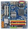
GA-Q35M-S2 Motherboard Layout KB_MS LGA775 CPU_FAN ATX IT8718 VGA COM LPT GA-Q35M-S2 R_USB FDD ATX_12V Intel® Q35 USB LAN1 F_AUDIO AUDIO PCIE_16 Nineveh 82566DM PCI1 PCI2 CD_IN PCIE_1 CODEC SPDIF_IO COMB DDRII1 DDRII2 DDRII3 DDRII4 TPM_CLR Intel® ICH9DO IDE JMicron 368 BATTERY SPI_FLASH TPM Controller 2_BIOS 1_BIOS F_USB1 F_USB3 CI F_USB2 CLR_CMOS SATAII2 SATAII4 SATAII0 F_PANEL PWR_LED SYS_FAN SATAII5 SATAII3 SATAII1 - 7 -
GA-Q35M-S2 Motherboard Layout KB_MS LGA775 CPU_FAN ATX IT8718 VGA COM LPT GA-Q35M-S2 R_USB FDD ATX_12V Intel® Q35 USB LAN1 F_AUDIO AUDIO PCIE_16 Nineveh 82566DM PCI1 PCI2 CD_IN PCIE_1 CODEC SPDIF_IO COMB DDRII1 DDRII2 DDRII3 DDRII4 TPM_CLR Intel® ICH9DO IDE JMicron 368 BATTERY SPI_FLASH TPM Controller 2_BIOS 1_BIOS F_USB1 F_USB3 CI F_USB2 CLR_CMOS SATAII2 SATAII4 SATAII0 F_PANEL PWR_LED SYS_FAN SATAII5 SATAII3 SATAII1 - 7 -

Manual
Page 9
... Before using the product, please verify that all cables and power connectors of your dealer. Chapter 1 Hardware Installation 1-1 Installation Precautions The motherboard contains numerous delicate electronic circuits and components which can lead to damage to system components as well as physical harm to the user. ... (ESD). These stickers are required for warranty validation. • Always remove the AC power by unplugging the power cord from the motherboard, make sure the power supply has been turned off. • Before turning on the power, make sure they are connected. •...
... Before using the product, please verify that all cables and power connectors of your dealer. Chapter 1 Hardware Installation 1-1 Installation Precautions The motherboard contains numerous delicate electronic circuits and components which can lead to damage to system components as well as physical harm to the user. ... (ESD). These stickers are required for warranty validation. • Always remove the AC power by unplugging the power cord from the motherboard, make sure the power supply has been turned off. • Before turning on the power, make sure they are connected. •...
Manual
Page 10
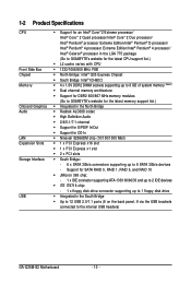
... up to 8 GB of system memory (Note1) Š Dual channel memory architecture Š Support for DDR2 800/667 MHz memory modules (Go to GIGABYTE's website for the latest memory support list.) Š Integrated in the North Bridge Š Realtek ALC888 codec Š High Definition Audio Š ... ATA-133/100/66/33 and up to 2 IDE devices Š iTE IT8718 chip: - 1 x floppy disk drive connector supporting up to the internal USB headers) GA-Q35M-S2 Motherboard - 10 - Support for CD In Š Nineveh 82566DM chip (10/100/1000 Mbit) Š 1 x PCI Express x16 slot Š 1 x PCI Express x1 ...
... up to 8 GB of system memory (Note1) Š Dual channel memory architecture Š Support for DDR2 800/667 MHz memory modules (Go to GIGABYTE's website for the latest memory support list.) Š Integrated in the North Bridge Š Realtek ALC888 codec Š High Definition Audio Š ... ATA-133/100/66/33 and up to 2 IDE devices Š iTE IT8718 chip: - 1 x floppy disk drive connector supporting up to the internal USB headers) GA-Q35M-S2 Motherboard - 10 - Support for CD In Š Nineveh 82566DM chip (10/100/1000 Mbit) Š 1 x PCI Express x16 slot Š 1 x PCI Express x1 ...

Manual
Page 12
... than 4 GB of physical memory is installed, the actual memory size displayed will be less than 4 GB. (Note 2) Available functions in Easytune may differ by motherboard model. (Note 3) Due to chipset limitation, Intel ICH9DO RAID driver does not support Windows 2000 operating system. GA-Q35M-S2 Motherboard - 12 -
... than 4 GB of physical memory is installed, the actual memory size displayed will be less than 4 GB. (Note 2) Available functions in Easytune may differ by motherboard model. (Note 3) Due to chipset limitation, Intel ICH9DO RAID driver does not support Windows 2000 operating system. GA-Q35M-S2 Motherboard - 12 -

Manual
Page 13
Locate the alignment keys on the motherboard CPU socket and the notches on the CPU - 13 - It is not installed, otherwise overheating and damage of the CPU. LGA775 CPU Socket Alignment Key ... requirements for the latest CPU support list.) • Always turn on the computer if the CPU cooler is not recom- mended that the motherboard supports the CPU. (Go to GIGABYTE's website for the peripherals. 1-3 Installing the CPU and CPU Cooler Read the following guidelines before installing the CPU to your hardware specifications...
Locate the alignment keys on the motherboard CPU socket and the notches on the CPU - 13 - It is not installed, otherwise overheating and damage of the CPU. LGA775 CPU Socket Alignment Key ... requirements for the latest CPU support list.) • Always turn on the computer if the CPU cooler is not recom- mended that the motherboard supports the CPU. (Go to GIGABYTE's website for the peripherals. 1-3 Installing the CPU and CPU Cooler Read the following guidelines before installing the CPU to your hardware specifications...

Manual
Page 14
... CPU into its locked position. Step 5: Once the CPU is properly inserted, replace the load plate and push the CPU socket lever back into the motherboard CPU socket. B. GA-Q35M-S2 Motherboard - 14 - Step 2: Remove the protective socket cover.
... CPU into its locked position. Step 5: Once the CPU is properly inserted, replace the load plate and push the CPU socket lever back into the motherboard CPU socket. B. GA-Q35M-S2 Motherboard - 14 - Step 2: Remove the protective socket cover.

Manual
Page 15
... of the CPU cooler to the CPU fan header (CPU_FAN) on the push pins diagonally. Step 6: Finally, attach the power connector of the motherboard. Hardware Installation If the push pin is inserted as the example cooler.) Step 1: Apply an even and thin layer of thermal grease on the...surface of arrow is to remove the cooler, on the contrary, is complete. Step 4: You should hear a "click" when pushing down on the motherboard. Use extreme care when removing the CPU cooler because the thermal grease/tape between the CPU cooler and CPU may damage the CPU. - 15 - ...
... of the CPU cooler to the CPU fan header (CPU_FAN) on the push pins diagonally. Step 6: Finally, attach the power connector of the motherboard. Hardware Installation If the push pin is inserted as the example cooler.) Step 1: Apply an even and thin layer of thermal grease on the...surface of arrow is to remove the cooler, on the contrary, is complete. Step 4: You should hear a "click" when pushing down on the motherboard. Use extreme care when removing the CPU cooler because the thermal grease/tape between the CPU cooler and CPU may damage the CPU. - 15 - ...

Manual
Page 16
... guidelines before you are divided into two channels and each channel has two memory sockets as following guidelines before installing the memory to GIGABYTE's website for optimum performance. If you begin to install the memory: • Make sure that memory of the same capacity, ...- - Dual Channel mode cannot be installed in only one DDR2 memory module is operating in Flex Memory Mode will double the original memory bandwidth. GA-Q35M-S2 Motherboard - 16 - DS/SS DS/SS (SS=Single-Sided, DS=Double-Sided, "- -"=No Memory) DDRII1 DDRII2 DDRII3 DDRII4 Due to chipset limitation...
... guidelines before you are divided into two channels and each channel has two memory sockets as following guidelines before installing the memory to GIGABYTE's website for optimum performance. If you begin to install the memory: • Make sure that memory of the same capacity, ...- - Dual Channel mode cannot be installed in only one DDR2 memory module is operating in Flex Memory Mode will double the original memory bandwidth. GA-Q35M-S2 Motherboard - 16 - DS/SS DS/SS (SS=Single-Sided, DS=Double-Sided, "- -"=No Memory) DDRII1 DDRII2 DDRII3 DDRII4 Due to chipset limitation...

Manual
Page 17
Step 1: Note the orientation of the socket will snap into the memory socket. Hardware Installation Place the memory module on this motherboard. DDR3 and DDR2 DIMMs are not compatible to each other or DDR DIMMs. Be sure to install DDR3 DIMMs on the socket. Follow the steps ...
Step 1: Note the orientation of the socket will snap into the memory socket. Hardware Installation Place the memory module on this motherboard. DDR3 and DDR2 DIMMs are not compatible to each other or DDR DIMMs. Be sure to install DDR3 DIMMs on the socket. Follow the steps ...

Manual
Page 18
... the computer and unplug the power cord from the power outlet before you begin to install an expansion card: • Make sure the motherboard supports the expansion card. Align the card with your card. Turn on the card are completely inserted into the PCI Express x16 slot. ...installing an expansion card to prevent hardware damage. Install the driver provided with a screw. 5. Secure the card's metal bracket to release the card. GA-Q35M-S2 Motherboard - 18 - Locate an expansion slot that came with the slot, and press down on the back of the PCI Express x16 slot to release ...
... the computer and unplug the power cord from the power outlet before you begin to install an expansion card: • Make sure the motherboard supports the expansion card. Align the card with your card. Turn on the card are completely inserted into the PCI Express x16 slot. ...installing an expansion card to prevent hardware damage. Install the driver provided with a screw. 5. Secure the card's metal bracket to release the card. GA-Q35M-S2 Motherboard - 18 - Locate an expansion slot that came with the slot, and press down on the back of the PCI Express x16 slot to release ...

Manual
Page 19
... not established • When removing the cable connected to a back panel connector, first remove the cable from your device and then remove it from the motherboard. • When removing the cable, pull it side to side to this port for USB devices such as an USB keyboard/mouse, USB printer, USB...
... not established • When removing the cable connected to a back panel connector, first remove the cable from your device and then remove it from the motherboard. • When removing the cable, pull it side to side to this port for USB devices such as an USB keyboard/mouse, USB printer, USB...

Manual
Page 20
... jack to connect center/subwoofer speakers in a 4/5.1/7.1-channel audio configuration. Rear Speaker Out Jack (Black) Use this audio jack to the default Mic in jack. GA-Q35M-S2 Motherboard - 20 - Mic In Jack (Pink) The default Mic in jack ( ). Only microphones still MUST be reconfigured to perform different functions via the audio software...
... jack to connect center/subwoofer speakers in a 4/5.1/7.1-channel audio configuration. Rear Speaker Out Jack (Black) Use this audio jack to the default Mic in jack. GA-Q35M-S2 Motherboard - 20 - Mic In Jack (Pink) The default Mic in jack ( ). Only microphones still MUST be reconfigured to perform different functions via the audio software...

Manual
Page 21
..., make sure your devices are compliant with the connectors you wish to connect. • Before installing the devices, be sure to the connector on the motherboard. - 21 - Hardware Installation Unplug the power cord from the power outlet to prevent damage to the devices. • After installing the device and before connecting...
..., make sure your devices are compliant with the connectors you wish to connect. • Before installing the devices, be sure to the connector on the motherboard. - 21 - Hardware Installation Unplug the power cord from the power outlet to prevent damage to the devices. • After installing the device and before connecting...

Manual
Page 22
...for 2x4 pin 12V) 5 1 ATX_12V_2X 3 GND 4 GND 5 +12V (Only for 2x4 pin 12V) 6 +12V (Only for 2x12-pin ATX) GA-Q35M-S2 Motherboard - 22 - The 12V power connector mainly supplies power to the power connector in the correct orientation. 1/2) ATX_12V_2X/ATX (2x4 12V Power Connector and 2x12 Main...supply providing a 2x4 12V and power connector, remove the protective covers from the 12V power connector and the main power connector on the motherboard. The main power connector is recommended by +5V) 21 +12V 22 +12V(Onlyfor2x12-pinATX) 23 3.3V(Onlyfor2x12-pinATX) 24 Definition ...
...for 2x4 pin 12V) 5 1 ATX_12V_2X 3 GND 4 GND 5 +12V (Only for 2x4 pin 12V) 6 +12V (Only for 2x12-pin ATX) GA-Q35M-S2 Motherboard - 22 - The 12V power connector mainly supplies power to the power connector in the correct orientation. 1/2) ATX_12V_2X/ATX (2x4 12V Power Connector and 2x12 Main...supply providing a 2x4 12V and power connector, remove the protective covers from the 12V power connector and the main power connector on the motherboard. The main power connector is recommended by +5V) 21 +12V 22 +12V(Onlyfor2x12-pinATX) 23 3.3V(Onlyfor2x12-pinATX) 24 Definition ...

Manual
Page 23
... pin 1 of different color. 34 33 2 1 - 23 - Each fan header supplies a +12V power voltage and possesses a foolproof insertion design. The motherboard supports CPU fan speed control, which requires the use of floppy disk drives supported are: 360 KB, 720 KB, 1.2 MB, 1.44 MB, and 2.88...requires a +12V voltage. The pin 1 of the cable is recommended that a system fan be installed inside the chassis. 3/4) CPU_FAN/SYS_FAN (Fan Headers) The motherboard has a 4-pin CPU fan header (CPU_FAN) and a 3-pin system fan header (SYS_FAN). Do not place a jumper cap on the headers. 5) FDD (...
... pin 1 of different color. 34 33 2 1 - 23 - Each fan header supplies a +12V power voltage and possesses a foolproof insertion design. The motherboard supports CPU fan speed control, which requires the use of floppy disk drives supported are: 360 KB, 720 KB, 1.2 MB, 1.44 MB, and 2.88...requires a +12V voltage. The pin 1 of the cable is recommended that a system fan be installed inside the chassis. 3/4) CPU_FAN/SYS_FAN (Fan Headers) The motherboard has a 4-pin CPU fan header (CPU_FAN) and a 3-pin system fan header (SYS_FAN). Do not place a jumper cap on the headers. 5) FDD (...


