
Manual
Page 1
...RAID 0, RAID 1, or other supported RAID array depending on your hard drive read/write performance without the need for RAID 0. Using GIGABYTE eXtreme Hard Drive (X.H.D) Instructions:(Note 2) Before launching X.H.D, make sure the new drive is recommended that before you 'll not be recognized... during the Windows setup process. (For more details, refer to enhance your needs and hardware components. 3. A. To manually set up all motherboard drivers, including the X.H.D utility. Or you have to access the Intel Matrix Storage Console, with a simple click of data. (Note 3)...
...RAID 0, RAID 1, or other supported RAID array depending on your hard drive read/write performance without the need for RAID 0. Using GIGABYTE eXtreme Hard Drive (X.H.D) Instructions:(Note 2) Before launching X.H.D, make sure the new drive is recommended that before you 'll not be recognized... during the Windows setup process. (For more details, refer to enhance your needs and hardware components. 3. A. To manually set up all motherboard drivers, including the X.H.D utility. Or you have to access the Intel Matrix Storage Console, with a simple click of data. (Note 3)...
Manual
Page 1
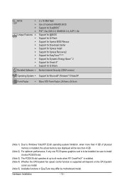
GA-P55M-UD2 LGA1156 socket motherboard for Intel® Core™ i7 processor family/ Intel® Core™ i5 processor family User's Manual Rev. 1001 12ME-P55MUD2-1001R
GA-P55M-UD2 LGA1156 socket motherboard for Intel® Core™ i7 processor family/ Intel® Core™ i5 processor family User's Manual Rev. 1001 12ME-P55MUD2-1001R

Manual
Page 3
... reproduced, copied, translated, transmitted, or published in this manual is protected by GIGABYTE without GIGABYTE's prior written permission. For detailed product information, carefully read or download the information on/from the Support&Downloads\Motherboard\Technology Guide page on your motherboard revision before updating motherboard BIOS, drivers, or when looking for technical information. No part of...
... reproduced, copied, translated, transmitted, or published in this manual is protected by GIGABYTE without GIGABYTE's prior written permission. For detailed product information, carefully read or download the information on/from the Support&Downloads\Motherboard\Technology Guide page on your motherboard revision before updating motherboard BIOS, drivers, or when looking for technical information. No part of...

Manual
Page 4
Table of Contents Box Contents...6 Optional Items...6 GA-P55M-UD2 Motherboard Layout 7 Block Diagram...8 Chapter 1 Hardware Installation 9 1-1 Installation Precautions 9 1-2 Product Specifications 10 1-3 Installing the CPU and CPU Cooler 13 1-3-1 Installing the CPU 13 1-3-2 Installing the CPU ...
Table of Contents Box Contents...6 Optional Items...6 GA-P55M-UD2 Motherboard Layout 7 Block Diagram...8 Chapter 1 Hardware Installation 9 1-1 Installation Precautions 9 1-2 Product Specifications 10 1-3 Installing the CPU and CPU Cooler 13 1-3-1 Installing the CPU 13 1-3-2 Installing the CPU ...
Manual
Page 6
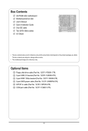
The box contents are for reference only. Box Contents GA-P55M-UD2 motherboard Motherboard driver disk User's Manual Quick Installation Guide One IDE cable Two SATA 3Gb/s cables I/O Shield • The box contents above are subject to change without notice. • The motherboard image is for reference only and the actual items shall depend on the product...
The box contents are for reference only. Box Contents GA-P55M-UD2 motherboard Motherboard driver disk User's Manual Quick Installation Guide One IDE cable Two SATA 3Gb/s cables I/O Shield • The box contents above are subject to change without notice. • The motherboard image is for reference only and the actual items shall depend on the product...

Manual
Page 7
GA-P55M-UD2 Motherboard Layout KB_USB R_SPDIF R_USB_2 CPU_FAN ATX_12V_2X4 LGA1156 PHASE LED ATX IT8720 GA-P55M-UD2 DDR3_2 DDR3_1 DDR3_4 DDR3_3 R_USB_1 USB_1394_ESATA USB_LAN RTL8111D AUDIO BAT F_AUDIO PCIEX16 PCI1 CODEC PCI2 CD_IN PCIEX4 SPDIF_O SPDIF_I FDD B_BIOS M_BIOS IDE GIGABYTE SATA2 TSB43AB23 Intel® P55 SATA2_4 CLR_CMOS SYS_FAN GSATA2_1 GSATA2_0 SATA2_1 SATA2_0 SATA2_3 SATA2_2 COMA F1_1394 F_USB2 F_USB1 F_PANEL - 7 -
GA-P55M-UD2 Motherboard Layout KB_USB R_SPDIF R_USB_2 CPU_FAN ATX_12V_2X4 LGA1156 PHASE LED ATX IT8720 GA-P55M-UD2 DDR3_2 DDR3_1 DDR3_4 DDR3_3 R_USB_1 USB_1394_ESATA USB_LAN RTL8111D AUDIO BAT F_AUDIO PCIEX16 PCI1 CODEC PCI2 CD_IN PCIEX4 SPDIF_O SPDIF_I FDD B_BIOS M_BIOS IDE GIGABYTE SATA2 TSB43AB23 Intel® P55 SATA2_4 CLR_CMOS SYS_FAN GSATA2_1 GSATA2_0 SATA2_1 SATA2_0 SATA2_3 SATA2_2 COMA F1_1394 F_USB2 F_USB1 F_PANEL - 7 -
Manual
Page 9
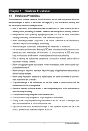
... related to the use of the product, please consult a certified computer technician. - 9 - Chapter 1 Hardware Installation 1-1 Installation Precautions The motherboard contains numerous delicate electronic circuits and components which can lead to damage to system components as well as physical harm to the user. •...system on an uneven surface. • Do not place the computer system in a high-temperature environment. • Turning on the motherboard, make sure the power supply voltage has been set according to the local voltage standard. • Before using the product, please ...
... related to the use of the product, please consult a certified computer technician. - 9 - Chapter 1 Hardware Installation 1-1 Installation Precautions The motherboard contains numerous delicate electronic circuits and components which can lead to damage to system components as well as physical harm to the user. •...system on an uneven surface. • Do not place the computer system in a high-temperature environment. • Turning on the motherboard, make sure the power supply voltage has been set according to the local voltage standard. • Before using the product, please ...
Manual
Page 12
... CPU/system fan speed control function is supported will depend on the CPU/system cooler you install. (Note 5) Available functions in EasyTune may differ by motherboard model.
... CPU/system fan speed control function is supported will depend on the CPU/system cooler you install. (Note 5) Available functions in EasyTune may differ by motherboard model.
Manual
Page 13
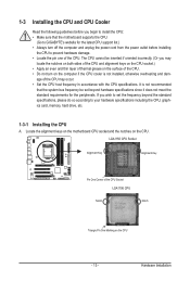
...please do so according to prevent hardware damage. • Locate the pin one of the CPU. Hardware Installation Locate the alignment keys on the motherboard CPU socket and the notches on the CPU - 13 - LGA1156 CPU Socket Alignment Key Alignment Key Pin One Corner of the CPU. &#...you may occur. • Set the CPU host frequency in accordance with the CPU specifications. It is not recommended that the motherboard supports the CPU. (Go to GIGABYTE's website for the peripherals. The CPU cannot be inserted if oriented incorrectly. (Or you begin to install the CPU: •...
...please do so according to prevent hardware damage. • Locate the pin one of the CPU. Hardware Installation Locate the alignment keys on the motherboard CPU socket and the notches on the CPU - 13 - LGA1156 CPU Socket Alignment Key Alignment Key Pin One Corner of the CPU. &#...you may occur. • Set the CPU host frequency in accordance with the CPU specifications. It is not recommended that the motherboard supports the CPU. (Go to GIGABYTE's website for the peripherals. The CPU cannot be inserted if oriented incorrectly. (Or you begin to install the CPU: •...

Manual
Page 14
... pin one marking (triangle) with the pin one hand to hold the socket lever and use the other to correctly install the CPU into the motherboard CPU socket. Follow the steps below to lightly replace the load plate. Before installing the CPU, make sure the front end of the CPU socket...
... pin one marking (triangle) with the pin one hand to hold the socket lever and use the other to correctly install the CPU into the motherboard CPU socket. Follow the steps below to lightly replace the load plate. Before installing the CPU, make sure the front end of the CPU socket...
Manual
Page 15
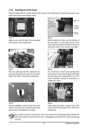
...contrary, is complete. If the push pin is inserted as the picture above shows, the installation is to correctly install the CPU cooler on the motherboard. (The following procedure uses Intel® boxed cooler as the example cooler.) Step 1: Apply an even and thin layer of thermal grease on ...Cooler Follow the steps below to install.) Step 3: Place the cooler atop the CPU, aligning the four push pins through the pin holes on the motherboard. Push down each push pin. Step 6: Finally, attach the power connector of the installed CPU. Inadequately removing the CPU cooler may adhere to ...
...contrary, is complete. If the push pin is inserted as the picture above shows, the installation is to correctly install the CPU cooler on the motherboard. (The following procedure uses Intel® boxed cooler as the example cooler.) Step 1: Apply an even and thin layer of thermal grease on ...Cooler Follow the steps below to install.) Step 3: Place the cooler atop the CPU, aligning the four push pins through the pin holes on the motherboard. Push down each push pin. Step 6: Finally, attach the power connector of the installed CPU. Inadequately removing the CPU cooler may adhere to ...

Manual
Page 16
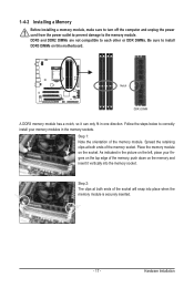
...Dual Channel Memory Configurations Table DDR3_2 DDR3_1 DDR3_4 Two Modules - - If you begin to install the memory: • Make sure that the motherboard supports the memory. Enabling Dual Channel memory mode will automatically detect the specifications and capacity of the same capacity, brand, speed, and chips ... it is recommended that memory of the memory. When enabling Dual Channel mode with two memory modules, be used . (Go to GIGABYTE's website for optimum performance. Dual Channel mode cannot be enabled if only one DDR3 memory module is installed, it is recommended to ...
...Dual Channel Memory Configurations Table DDR3_2 DDR3_1 DDR3_4 Two Modules - - If you begin to install the memory: • Make sure that the motherboard supports the memory. Enabling Dual Channel memory mode will automatically detect the specifications and capacity of the same capacity, brand, speed, and chips ... it is recommended that memory of the memory. When enabling Dual Channel mode with two memory modules, be used . (Go to GIGABYTE's website for optimum performance. Dual Channel mode cannot be enabled if only one DDR3 memory module is installed, it is recommended to ...
Manual
Page 17
... memory and insert it can only fit in the memory sockets. Follow the steps below to the memory module. Place the memory module on this motherboard. As indicated in the picture on the left, place your memory modules in one direction. Spread the retaining clips at both ends of the memory...
... memory and insert it can only fit in the memory sockets. Follow the steps below to the memory module. Place the memory module on this motherboard. As indicated in the picture on the left, place your memory modules in one direction. Spread the retaining clips at both ends of the memory...

Manual
Page 18
... on the card until it is fully inserted into the slot. 4. Secure the card's metal bracket to install an expansion card: • Make sure the motherboard supports the expansion card. After installing all expansion cards, replace the chassis cover(s). 6. Example: Installing and Removing a PCI Express Graphics Card: • Installing a Graphics Card...
... on the card until it is fully inserted into the slot. 4. Secure the card's metal bracket to install an expansion card: • Make sure the motherboard supports the expansion card. After installing all expansion cards, replace the chassis cover(s). 6. Example: Installing and Removing a PCI Express Graphics Card: • Installing a Graphics Card...

Manual
Page 19
... the cable connector. - 19 - Do not rock it side to side to an external audio system that your device and then remove it from the motherboard. • When removing the cable, pull it straight out from your audio system provides an optical digital audio in connector.
... the cable connector. - 19 - Do not rock it side to side to an external audio system that your device and then remove it from the motherboard. • When removing the cable, pull it straight out from your audio system provides an optical digital audio in connector.

Manual
Page 21
... devices and your devices are compliant with the connectors you wish to connect. • Before installing the devices, be sure to the connector on the motherboard. - 21 - 1-7 Internal Connectors 13 19 2 6 11 9 8 7 12 4 14 13 5 17 16 18 15 10 1) ATX_12V_2X4 2) ATX 3) CPU_FAN 4) SYS_FAN 5) FDD 6) IDE 7) SATA2_0/1/2/3/4 8) GSATA2_0/1 9) BAT 10) F_PANEL...
... devices and your devices are compliant with the connectors you wish to connect. • Before installing the devices, be sure to the connector on the motherboard. - 21 - 1-7 Internal Connectors 13 19 2 6 11 9 8 7 12 4 14 13 5 17 16 18 15 10 1) ATX_12V_2X4 2) ATX 3) CPU_FAN 4) SYS_FAN 5) FDD 6) IDE 7) SATA2_0/1/2/3/4 8) GSATA2_0/1 9) BAT 10) F_PANEL...
Manual
Page 22
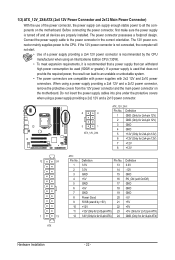
The power connector possesses a foolproof design. If a power supply is turned off and all the components on the motherboard. Do not insert the power supply cables into pins under the protective covers when using a power supply providing a 2x4 12V and a 2x12 ...power connector, remove the protective covers from the 12V power connector and the main power connector on the motherboard. 1/2) ATX_12V_2X4/ATX (2x4 12V Power Connector and 2x12 Main Power Connector) With the use of a power supply providing a 2x4 12V power connector is...
The power connector possesses a foolproof design. If a power supply is turned off and all the components on the motherboard. Do not insert the power supply cables into pins under the protective covers when using a power supply providing a 2x4 12V and a 2x12 ...power connector, remove the protective covers from the 12V power connector and the main power connector on the motherboard. 1/2) ATX_12V_2X4/ATX (2x4 12V Power Connector and 2x12 Main Power Connector) With the use of a power supply providing a 2x4 12V power connector is...
Manual
Page 23
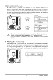
... may result in the correct orientation (the black connector wire is recommended that a system fan be sure to connect it is the ground wire). The motherboard supports CPU fan speed control, which requires the use of the connector and the floppy disk drive cable. Definition 1 GND 2 +12V / Speed Control 3 Sense 4 ...or the system may hang. • These fan headers are : 360 KB, 720 KB, 1.2 MB, 1.44 MB, and 2.88 MB. 3/4) CPU_FAN/SYS_FAN (Fan Headers) The motherboard has a 4-pin CPU fan header (CPU_FAN) and a 4-pin (SYS_FAN). Most fan headers possess a foolproof insertion design.
... may result in the correct orientation (the black connector wire is recommended that a system fan be sure to connect it is the ground wire). The motherboard supports CPU fan speed control, which requires the use of the connector and the floppy disk drive cable. Definition 1 GND 2 +12V / Speed Control 3 Sense 4 ...or the system may hang. • These fan headers are : 360 KB, 720 KB, 1.2 MB, 1.44 MB, and 2.88 MB. 3/4) CPU_FAN/SYS_FAN (Fan Headers) The motherboard has a 4-pin CPU fan header (CPU_FAN) and a 4-pin (SYS_FAN). Most fan headers possess a foolproof insertion design.

Manual
Page 27
... front panel audio header supports HD audio by default. Definition Pin No. Incorrect connection between the module connector and the motherboard header will be present on each wire instead of the motherboard header. Definition 1 1 CD-L 2 GND 3 GND 4 CD-R - 27 - 11) F_AUDIO (Front Panel Audio Header) The front panel audio header supports Intel...
... front panel audio header supports HD audio by default. Definition Pin No. Incorrect connection between the module connector and the motherboard header will be present on each wire instead of the motherboard header. Definition 1 1 CD-L 2 GND 3 GND 4 CD-R - 27 - 11) F_AUDIO (Front Panel Audio Header) The front panel audio header supports Intel...

Manual
Page 28
... your expansion card. Pin No. For example, some graphics cards may require you to the graphics card and have digital audio output from your motherboard to your motherboard to an audio device that supports digital audio out via an optional S/PDIF In cable. For purchasing the optional S/PDIF In cable, please contact...
... your expansion card. Pin No. For example, some graphics cards may require you to the graphics card and have digital audio output from your motherboard to your motherboard to an audio device that supports digital audio out via an optional S/PDIF In cable. For purchasing the optional S/PDIF In cable, please contact...


