
Manual
Page 1
...screen to individually install the X.H.D utility later. Using GIGABYTE eXtreme Hard Drive (X.H.D) Instructions:(Note 2) Before launching X.H.D, make sure the new drive is greater than or equal to automatically set up all motherboard drivers, including the X.H.D utility. A. Without the ...Chapter 5, "Installing the SATA RAID/AHCI Driver and Operating System." ) Step 3: Install the motherboard drivers and the X.H.D utiltiy After installing the operating system, insert the motherboard driver disk. To manually set eXtreme Hard Drive (X.H.D) under the Integrated Peripherals menu to Enabled...
...screen to individually install the X.H.D utility later. Using GIGABYTE eXtreme Hard Drive (X.H.D) Instructions:(Note 2) Before launching X.H.D, make sure the new drive is greater than or equal to automatically set up all motherboard drivers, including the X.H.D utility. A. Without the ...Chapter 5, "Installing the SATA RAID/AHCI Driver and Operating System." ) Step 3: Install the motherboard drivers and the X.H.D utiltiy After installing the operating system, insert the motherboard driver disk. To manually set eXtreme Hard Drive (X.H.D) under the Integrated Peripherals menu to Enabled...

Manual
Page 4
... "Xpress Install" will install all of Smart TPM to install the Infineon TPM driver and the Smart TPM utility altogether. - 4 - Some motherboard driver disks include the Smart TPM utility in "Xpress Install." Click the "Install All" button on the right of the drivers that the Infineon... TPM driver and the Smart TPM utility have been installed. 2.1. Installing the Infineon TPM Driver Insert the GIGABYTE motherboard driver disk. Click the Install All button and "Xpress Install" will automatically scan your system and list all of the autorun screen...
... "Xpress Install" will install all of Smart TPM to install the Infineon TPM driver and the Smart TPM utility altogether. - 4 - Some motherboard driver disks include the Smart TPM utility in "Xpress Install." Click the "Install All" button on the right of the drivers that the Infineon... TPM driver and the Smart TPM utility have been installed. 2.1. Installing the Infineon TPM Driver Insert the GIGABYTE motherboard driver disk. Click the Install All button and "Xpress Install" will automatically scan your system and list all of the autorun screen...

Manual
Page 7
... phone key: Select the Use Bluetooth Device check box and click Refresh to search for pairing. Before creating a Bluetooth cell phone key, make sure your motherboard includes a Bluetooth receiver and turn on the search and Bluetooth functions on your cell phone for the USB flash drive(s) that you plug in the...
... phone key: Select the Use Bluetooth Device check box and click Refresh to search for pairing. Before creating a Bluetooth cell phone key, make sure your motherboard includes a Bluetooth receiver and turn on the search and Bluetooth functions on your cell phone for the USB flash drive(s) that you plug in the...

Manual
Page 19
...'t display your Bluetooth-enabled cell phone, click Refresh to let Smart TPM re-detect the device.) Before creating a Bluetooth cell phone key, make sure your motherboard includes a Bluetooth receiver and turn off or reset your PSD by plugging in BIOS Setup and then set earlier and click OK to complete creating...
...'t display your Bluetooth-enabled cell phone, click Refresh to let Smart TPM re-detect the device.) Before creating a Bluetooth cell phone key, make sure your motherboard includes a Bluetooth receiver and turn off or reset your PSD by plugging in BIOS Setup and then set earlier and click OK to complete creating...
Manual
Page 1
GA-P55A-UD6 LGA1156 socket motherboard for Intel® Core™ i7 processor family/ Intel® Core™ i5 processor family User's Manual Rev. 1002 12ME-P55AUD6-1002R
GA-P55A-UD6 LGA1156 socket motherboard for Intel® Core™ i7 processor family/ Intel® Core™ i5 processor family User's Manual Rev. 1002 12ME-P55AUD6-1002R
Manual
Page 2
Motherboard GA-P55A-UD6 Oct. 16, 2009 Motherboard GA-P55A-UD6 Oct. 16, 2009
Motherboard GA-P55A-UD6 Oct. 16, 2009 Motherboard GA-P55A-UD6 Oct. 16, 2009
Manual
Page 3
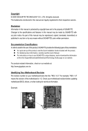
Disclaimer Information in this : "REV: X.X." Example: For product-related information, check on our website at: http://www.gigabyte.com.tw Identifying Your Motherboard Revision The revision number on our website. Check your motherboard looks like this manual are legally registered to the specifications and features in this manual may be reproduced, copied, translated, transmitted...
Disclaimer Information in this : "REV: X.X." Example: For product-related information, check on our website at: http://www.gigabyte.com.tw Identifying Your Motherboard Revision The revision number on our website. Check your motherboard looks like this manual are legally registered to the specifications and features in this manual may be reproduced, copied, translated, transmitted...
Manual
Page 4
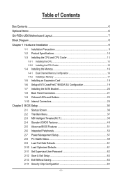
Table of Contents Box Contents...6 Optional Items...6 GA-P55A-UD6 Motherboard Layout 7 Block Diagram...8 Chapter 1 Hardware Installation 9 1-1 Installation Precautions 9 1-2 Product Specifications 10 1-3 Installing the CPU and CPU Cooler 13 1-3-1 Installing the CPU 13 1-3-2 Installing the CPU ...
Table of Contents Box Contents...6 Optional Items...6 GA-P55A-UD6 Motherboard Layout 7 Block Diagram...8 Chapter 1 Hardware Installation 9 1-1 Installation Precautions 9 1-2 Product Specifications 10 1-3 Installing the CPU and CPU Cooler 13 1-3-1 Installing the CPU 13 1-3-2 Installing the CPU ...
Manual
Page 6
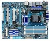
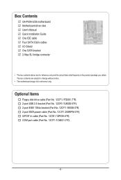
...SATA power cable (Part No. 12CF1-2SERPW-0*R) S/PDIF In cable (Part No. 12CR1-1SPDIN-0*R) COM port cable (Part No. 12CF1-1CM001-3*R) - 6 - Box Contents GA-P55A-UD6 motherboard Motherboard driver disk User's Manual Quick Installation Guide One IDE cable Four SATA 3Gb/s cables I/O Shield One SATA bracket 2-Way SLI bridge connector • The box... contents above are subject to change without notice. • The motherboard image is for reference only and the actual items shall depend on the product package you obtain.
...SATA power cable (Part No. 12CF1-2SERPW-0*R) S/PDIF In cable (Part No. 12CR1-1SPDIN-0*R) COM port cable (Part No. 12CF1-1CM001-3*R) - 6 - Box Contents GA-P55A-UD6 motherboard Motherboard driver disk User's Manual Quick Installation Guide One IDE cable Four SATA 3Gb/s cables I/O Shield One SATA bracket 2-Way SLI bridge connector • The box... contents above are subject to change without notice. • The motherboard image is for reference only and the actual items shall depend on the product package you obtain.
Manual
Page 7
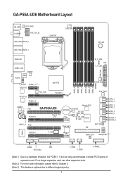
...is optional due to a hardware limitation, the PCIEX1_1 slot can only accommodate a shorter PCI Express x1 expansion card. GA-P55A-UD6 Motherboard Layout KB_USB R_SPDIF SYS_FAN3 ATX_12V_2X USB_1394_ESATA_2 USB_1394_ESATA_1 LGA1156 CPU_FAN PW_SW USB_LAN USB30_LAN JMB362 NEC AUDIO F_AUDIO PCIEX1_1 (Note 1) RTL8111D ...Intel® P55 RTL8111D PCH_FAN PCIEX16_1 CODEC CD_IN SPDIF_I PCIEX1_2 PCI1 PCIEX8_1 GA-P55A-UD6 TPM IC (Note 3) Marvell 9128 BATTERY B_BIOS S3_LED S0_LED M_BIOS S4_S5_LED S1_LED IT8213 SPDIF_O PCI2 TSB43AB23 IDE...
...is optional due to a hardware limitation, the PCIEX1_1 slot can only accommodate a shorter PCI Express x1 expansion card. GA-P55A-UD6 Motherboard Layout KB_USB R_SPDIF SYS_FAN3 ATX_12V_2X USB_1394_ESATA_2 USB_1394_ESATA_1 LGA1156 CPU_FAN PW_SW USB_LAN USB30_LAN JMB362 NEC AUDIO F_AUDIO PCIEX1_1 (Note 1) RTL8111D ...Intel® P55 RTL8111D PCH_FAN PCIEX16_1 CODEC CD_IN SPDIF_I PCIEX1_2 PCI1 PCIEX8_1 GA-P55A-UD6 TPM IC (Note 3) Marvell 9128 BATTERY B_BIOS S3_LED S0_LED M_BIOS S4_S5_LED S1_LED IT8213 SPDIF_O PCI2 TSB43AB23 IDE...
Manual
Page 9
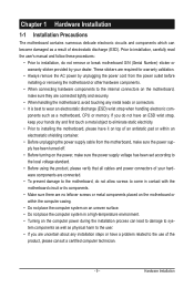
... electrostatic shielding container. • Before unplugging the power supply cable from the power outlet before installing or removing the motherboard or other hardware components. • When connecting hardware components to the internal connectors on the computer power during the... as a result of the product, please consult a certified computer technician. - 9 - Chapter 1 Hardware Installation 1-1 Installation Precautions The motherboard contains numerous delicate electronic circuits and components which can lead to damage to system components as well as physical harm to the user. &#...
... electrostatic shielding container. • Before unplugging the power supply cable from the power outlet before installing or removing the motherboard or other hardware components. • When connecting hardware components to the internal connectors on the computer power during the... as a result of the product, please consult a certified computer technician. - 9 - Chapter 1 Hardware Installation 1-1 Installation Precautions The motherboard contains numerous delicate electronic circuits and components which can lead to damage to system components as well as physical harm to the user. &#...

Manual
Page 12
... CPU/system fan speed control function is supported will depend on the CPU/system cooler you install. (Note 6) Available functions in EasyTune may differ by motherboard model. (Note 7) This feature is optional due to x8 mode. (Note 4) The default bandwidth for Microsoft® Windows 7/Vista/XP Form Factor w ATX Form Factor...
... CPU/system fan speed control function is supported will depend on the CPU/system cooler you install. (Note 6) Available functions in EasyTune may differ by motherboard model. (Note 7) This feature is optional due to x8 mode. (Note 4) The default bandwidth for Microsoft® Windows 7/Vista/XP Form Factor w ATX Form Factor...

Manual
Page 13
Locate the alignment keys on the motherboard CPU socket and the notches on the CPU - 13 - LGA1156 CPU Socket Alignment Key Alignment Key Pin One Corner of the CPU. • Do not ... computer and unplug the power cord from the power outlet before you begin to install the CPU: • Make sure that the motherboard supports the CPU. (Go to GIGABYTE's website for the peripherals. The CPU cannot be set the frequency beyond hardware specifications since it does not meet the standard requirements for...
Locate the alignment keys on the motherboard CPU socket and the notches on the CPU - 13 - LGA1156 CPU Socket Alignment Key Alignment Key Pin One Corner of the CPU. • Do not ... computer and unplug the power cord from the power outlet before you begin to install the CPU: • Make sure that the motherboard supports the CPU. (Go to GIGABYTE's website for the peripherals. The CPU cannot be set the frequency beyond hardware specifications since it does not meet the standard requirements for...

Manual
Page 14
... completely lift the CPU socket lever and the metal load plate will be lifted as shown. Step 5: Push the CPU socket lever back into the motherboard CPU socket. Align the CPU pin one marking (triangle) with the pin one hand to turn off the computer and unplug the power cord from...
... completely lift the CPU socket lever and the metal load plate will be lifted as shown. Step 5: Push the CPU socket lever back into the motherboard CPU socket. Align the CPU pin one marking (triangle) with the pin one hand to turn off the computer and unplug the power cord from...

Manual
Page 15
...manual for instructions on the push pins diagonally. 1-3-2 Installing the CPU Cooler Follow the steps below to correctly install the CPU cooler on the motherboard. (The following procedure uses Intel® boxed cooler as the picture above shows, the installation is to install.) Step 3: Place the ...After the installation, check the back of arrow is to the CPU fan header (CPU_FAN) on the surface of thermal grease on the motherboard. Inadequately removing the CPU cooler may adhere to the CPU. Hardware Installation Direction of the Arrow Sign on the Male Push Pin Male Push...
...manual for instructions on the push pins diagonally. 1-3-2 Installing the CPU Cooler Follow the steps below to correctly install the CPU cooler on the motherboard. (The following procedure uses Intel® boxed cooler as the picture above shows, the installation is to install.) Step 3: Place the ...After the installation, check the back of arrow is to the CPU fan header (CPU_FAN) on the surface of thermal grease on the motherboard. Inadequately removing the CPU cooler may adhere to the CPU. Hardware Installation Direction of the Arrow Sign on the Male Push Pin Male Push...

Manual
Page 16
...Enabling Dual Channel memory mode will automatically detect the specifications and capacity of the same capacity, brand, speed, and chips be used. (Go to GIGABYTE's website for optimum performance. The six DDR3 memory sockets are unable to install the memory: • Make sure that memory of the memory. ...DS/SS DS/SS DS - - If you begin to insert the memory, switch the direction. 1-4-1 Dual Channel Memory Configuration This motherboard provides six DDR3 memory sockets and supports Dual Channel Technology. When enabling Dual Channel mode, it is recommended that the...
...Enabling Dual Channel memory mode will automatically detect the specifications and capacity of the same capacity, brand, speed, and chips be used. (Go to GIGABYTE's website for optimum performance. The six DDR3 memory sockets are unable to install the memory: • Make sure that memory of the memory. ...DS/SS DS/SS DS - - If you begin to insert the memory, switch the direction. 1-4-1 Dual Channel Memory Configuration This motherboard provides six DDR3 memory sockets and supports Dual Channel Technology. When enabling Dual Channel mode, it is recommended that the...

Manual
Page 17
..., make sure to turn off the computer and unplug the power cord from the power outlet to prevent damage to install DDR3 DIMMs on this motherboard. Step 1: Note the orientation of the memory socket. DDR3 and DDR2 DIMMs are not compatible to each other or DDR DIMMs. Be sure to the...
..., make sure to turn off the computer and unplug the power cord from the power outlet to prevent damage to install DDR3 DIMMs on this motherboard. Step 1: Note the orientation of the memory socket. DDR3 and DDR2 DIMMs are not compatible to each other or DDR DIMMs. Be sure to the...
Manual
Page 18
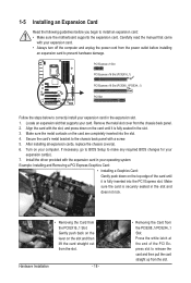
... turn off the computer and unplug the power cord from the power outlet before you begin to install an expansion card: • Make sure the motherboard supports the expansion card. PCI Express x1 Slot PCI Express x16 Slot (PCIEX16_1) PCI Express x16 Slot (PCIEX8_1/PCIEX4_1) PCI Slot Follow the steps below...
... turn off the computer and unplug the power cord from the power outlet before you begin to install an expansion card: • Make sure the motherboard supports the expansion card. PCI Express x1 Slot PCI Express x16 Slot (PCIEX16_1) PCI Express x16 Slot (PCIEX8_1/PCIEX4_1) PCI Slot Follow the steps below...

Manual
Page 19
... graphics card on the PCI Express x16 slots. C. Configuring the Graphics Card Driver C-1. System Requirements - Windows Vista or Windows XP operating system - A CrossFireX/SLI-supported motherboard with sufficient power is recommended (Refer to the NVIDIA Control Panel. Step 2: Insert the CrossFire (Note)/SLI bridge connectors in the operating system, go to...
... graphics card on the PCI Express x16 slots. C. Configuring the Graphics Card Driver C-1. System Requirements - Windows Vista or Windows XP operating system - A CrossFireX/SLI-supported motherboard with sufficient power is recommended (Refer to the NVIDIA Control Panel. Step 2: Insert the CrossFire (Note)/SLI bridge connectors in the operating system, go to...

Manual
Page 20
... SATA signal cable, make sure to hardware. • Insert the SATA signal cable and SATA power cable securely into the external SATA connector on your motherboard. SATA Bracket SATA Signal Cable SATA Power Cable External SATA Connector Power Connector External SATA Connector The SATA bracket includes one SATA bracket, one SATA...
... SATA signal cable, make sure to hardware. • Insert the SATA signal cable and SATA power cable securely into the external SATA connector on your motherboard. SATA Bracket SATA Signal Cable SATA Power Cable External SATA Connector Power Connector External SATA Connector The SATA bracket includes one SATA bracket, one SATA...


