
Manual
Page 1
...load the SATA controller driver first. Or you have to set up all motherboard drivers, including the X.H.D utility. eXtreme Hard Drive (X.H.D) With GIGABYTE eXtreme Hard Drive (X.H.D)(Note 1), users can quickly configure a RAIDready system for the Intel SATA controllers. A. Step 2: Install the RAID driver...system, you can click the Xpress Install All button to automatically install all of a button, X.H.D helps to expand its capacity. To manually set eXtreme Hard Drive (X.H.D) under the Integrated Peripherals menu to Enabled to enable RAID for RAID 0 when a new SATA drive is...
...load the SATA controller driver first. Or you have to set up all motherboard drivers, including the X.H.D utility. eXtreme Hard Drive (X.H.D) With GIGABYTE eXtreme Hard Drive (X.H.D)(Note 1), users can quickly configure a RAIDready system for the Intel SATA controllers. A. Step 2: Install the RAID driver...system, you can click the Xpress Install All button to automatically install all of a button, X.H.D helps to expand its capacity. To manually set eXtreme Hard Drive (X.H.D) under the Integrated Peripherals menu to Enabled to enable RAID for RAID 0 when a new SATA drive is...

Manual
Page 1
The original settings in Ultra TPM will be kept. Smart TPM User's Manual Rev. 1001 12MD-STPM-1001R • We recommend that you download the latest version of the Smart TPM utility from GIGABYTE's website. • If you have installed Ultra TPM earlier, you can install the Smart TPM utility directly without uninstalling Ultra TPM first.
The original settings in Ultra TPM will be kept. Smart TPM User's Manual Rev. 1001 12MD-STPM-1001R • We recommend that you download the latest version of the Smart TPM utility from GIGABYTE's website. • If you have installed Ultra TPM earlier, you can install the Smart TPM utility directly without uninstalling Ultra TPM first.
Manual
Page 15
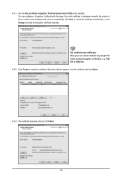
... certificates: Here you can configure a Encryption Certificate with this page. B-5-3. Click Next to create the certificate automatically, or click Change to create an encryption certificate manually. Key length for newly created encryption certificates, e.g. 1024 bits or 2048 bits.
... certificates: Here you can configure a Encryption Certificate with this page. B-5-3. Click Next to create the certificate automatically, or click Change to create an encryption certificate manually. Key length for newly created encryption certificates, e.g. 1024 bits or 2048 bits.
Manual
Page 21
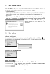
... View User Password to enable the TPM. When prompted, enter the TPM User Password to display the TPM User Password. To disable the TPM, select Manual Logout. Manual Login/Logout You can configure how much time it takes to 30 seconds in the notification area and select... Manual Login. Smart TPM searches for the key based on the length of time you can enable the TPM even if your portable user key is ...
... View User Password to enable the TPM. When prompted, enter the TPM User Password to display the TPM User Password. To disable the TPM, select Manual Logout. Manual Login/Logout You can configure how much time it takes to 30 seconds in the notification area and select... Manual Login. Smart TPM searches for the key based on the length of time you can enable the TPM even if your portable user key is ...
Manual
Page 1
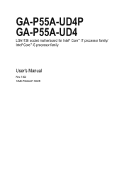
GA-P55A-UD4P GA-P55A-UD4 LGA1156 socket motherboard for Intel® Core™ i7 processor family/ Intel® Core™ i5 processor family User's Manual Rev. 1002 12ME-P55AU4P-1002R
GA-P55A-UD4P GA-P55A-UD4 LGA1156 socket motherboard for Intel® Core™ i7 processor family/ Intel® Core™ i5 processor family User's Manual Rev. 1002 12ME-P55AU4P-1002R
Manual
Page 3
... and is 1.0. For example, "REV: 1.0" means the revision of the motherboard is the property of this manual may be made by any means without prior notice. Example: All rights reserved. Disclaimer Information in the use GIGABYTE's unique features, read or download the information on/from the Support&Downloads\Motherboard\Technology Guide page...
... and is 1.0. For example, "REV: 1.0" means the revision of the motherboard is the property of this manual may be made by any means without prior notice. Example: All rights reserved. Disclaimer Information in the use GIGABYTE's unique features, read or download the information on/from the Support&Downloads\Motherboard\Technology Guide page...
Manual
Page 4
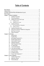
Table of Contents Box Contents...6 Optional Items...6 GA-P55A-UD4P/GA-P55A-UD4 Motherboard Layout 7 Block Diagram...8 Chapter 1 Hardware Installation 9 1-1 Installation Precautions 9 1-2 Product Specifications 10 1-3 Installing the CPU and CPU Cooler 13 1-3-1 Installing the CPU 13 1-3-2 Installing ... & Exit Setup 62 2-13 Exit Without Saving 62 2-14 Security Chip Configuration j 63 Chapter 3 Drivers Installation 65 3-1 Installing Chipset Drivers 65 3-2 Application Software 66 3-3 Technical Manuals 66 - 4 -
Table of Contents Box Contents...6 Optional Items...6 GA-P55A-UD4P/GA-P55A-UD4 Motherboard Layout 7 Block Diagram...8 Chapter 1 Hardware Installation 9 1-1 Installation Precautions 9 1-2 Product Specifications 10 1-3 Installing the CPU and CPU Cooler 13 1-3-1 Installing the CPU 13 1-3-2 Installing ... & Exit Setup 62 2-13 Exit Without Saving 62 2-14 Security Chip Configuration j 63 Chapter 3 Drivers Installation 65 3-1 Installing Chipset Drivers 65 3-2 Application Software 66 3-3 Technical Manuals 66 - 4 -
Manual
Page 6
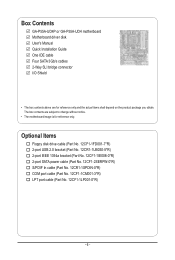
The box contents are for reference only. Box Contents GA-P55A-UD4P or GA-P55A-UD4 motherboard Motherboard driver disk User's Manual Quick Installation Guide One IDE cable Four SATA 3Gb/s cables 2-Way SLI bridge connector I/O Shield • The box contents above are subject to change without ...
The box contents are for reference only. Box Contents GA-P55A-UD4P or GA-P55A-UD4 motherboard Motherboard driver disk User's Manual Quick Installation Guide One IDE cable Four SATA 3Gb/s cables 2-Way SLI bridge connector I/O Shield • The box contents above are subject to change without ...
Manual
Page 9
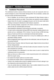
... have it on the computer power during the installation process can become damaged as a motherboard, CPU or memory. Prior to installation, carefully read the user's manual and follow these procedures: • Prior to installation, do not allow screws to come in a high-temperature environment. • Turning on top of your dealer...
... have it on the computer power during the installation process can become damaged as a motherboard, CPU or memory. Prior to installation, carefully read the user's manual and follow these procedures: • Prior to installation, do not allow screws to come in a high-temperature environment. • Turning on top of your dealer...
Manual
Page 15
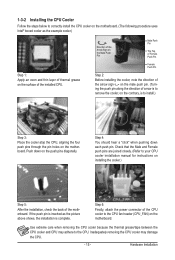
... pin along the direction of the installed CPU. Check that the Male and Female push pins are joined closely. (Refer to your CPU cooler installation manual for instructions on installing the cooler.) Step 5: After the installation, check the back of the CPU cooler to the CPU fan header (CPU_FAN) on the...
... pin along the direction of the installed CPU. Check that the Male and Female push pins are joined closely. (Refer to your CPU cooler installation manual for instructions on installing the cooler.) Step 5: After the installation, check the back of the CPU cooler to the CPU fan header (CPU_FAN) on the...
Manual
Page 18
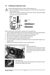
...; Removing the Card: Press the white latch at the end of the card until it is fully seated in the expansion slot. 1. Carefully read the manual that supports your expansion card. • Always turn off the computer and unplug the power cord from the chassis back panel. 2. Secure the card's metal...
...; Removing the Card: Press the white latch at the end of the card until it is fully seated in the expansion slot. 1. Carefully read the manual that supports your expansion card. • Always turn off the computer and unplug the power cord from the chassis back panel. 2. Secure the card's metal...
Manual
Page 19
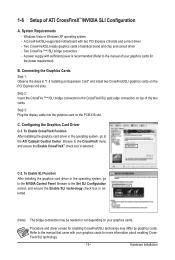
...Refer to the NVIDIA Control Panel. Step 3: Plug the display cable into the graphics card on the PCI Express x16 slots. C. Browse to the manual that came with your graphics cards for more information about enabling CrossFireX/SLI technology. - 19 - Refer to the CrossFireX menu and ensure the Enable ...CrossFireX/SLI graphics cards on the PCIEX16 slot. Connecting the Graphics Cards Step 1: Observe the steps in the operating system, go to the manual of ATI CrossFireX™/NVIDIA SLI Configuration A. Hardware Installation Windows Vista or Windows XP operating system -
...Refer to the NVIDIA Control Panel. Step 3: Plug the display cable into the graphics card on the PCI Express x16 slots. C. Browse to the manual that came with your graphics cards for more information about enabling CrossFireX/SLI technology. - 19 - Refer to the CrossFireX menu and ensure the Enable ...CrossFireX/SLI graphics cards on the PCIEX16 slot. Connecting the Graphics Cards Step 1: Observe the steps in the operating system, go to the manual of ATI CrossFireX™/NVIDIA SLI Configuration A. Hardware Installation Windows Vista or Windows XP operating system -

Manual
Page 29
For information about connecting the S/PDIF digital audio cable, carefully read the manual for your motherboard to use a S/PDIF digital audio cable for digital audio output from the HDMI display at the same time. 14) SPDIF_I (S/PDIF In ...
For information about connecting the S/PDIF digital audio cable, carefully read the manual for your motherboard to use a S/PDIF digital audio cable for digital audio output from the HDMI display at the same time. 14) SPDIF_I (S/PDIF In ...
Manual
Page 32
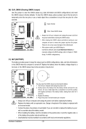
... accurate or may cause damage to the motherboard. • After system restart, go to BIOS Setup to load factory defaults (select Load Optimized Defaults) or manually configure the BIOS settings (refer to keep the values (such as BIOS configurations, date, and time information) in the CMOS when the computer is replaced...
... accurate or may cause damage to the motherboard. • After system restart, go to BIOS Setup to load factory defaults (select Load Optimized Defaults) or manually configure the BIOS settings (refer to keep the values (such as BIOS configurations, date, and time information) in the CMOS when the computer is replaced...

Manual
Page 42
..., when system instability occurs after overclocking, lower the overclocking ratio. >>>>> Advanced Clock Control CPU Clock Drive Allows you to manually set the system memory multiplier. PCI Express Clock Drive Allows you to manually set in accordance with the CPU specifications. Important: It is highly recommended that is the normal operating frequency of...
..., when system instability occurs after overclocking, lower the overclocking ratio. >>>>> Advanced Clock Control CPU Clock Drive Allows you to manually set the system memory multiplier. PCI Express Clock Drive Allows you to manually set in accordance with the CPU specifications. Important: It is highly recommended that is the normal operating frequency of...
Manual
Page 49
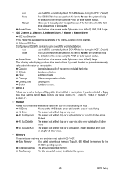
...The following fields display your IDE/SATA devices by the BIOS POST. Landing Zone Landing zone. Drive A Allows you wish to enter the parameters manually, refer to the information on the system. - 49 - Halt On Allows you to determine whether the system will stop for an error during ...drive access mode. Extended IDE Drive Configure your hard drive specifications. Sector Number of memory installed on the hard drive. If you to manually enter the specifications of the hard drive when the hard drive access mode is set to CHS. No Errors The system boot will not...
...The following fields display your IDE/SATA devices by the BIOS POST. Landing Zone Landing zone. Drive A Allows you wish to enter the parameters manually, refer to the information on the system. - 49 - Halt On Allows you to determine whether the system will stop for an error during ...drive access mode. Extended IDE Drive Configure your hard drive specifications. Sector Number of memory installed on the hard drive. If you to manually enter the specifications of the hard drive when the hard drive access mode is set to CHS. No Errors The system boot will not...
Manual
Page 65
Or click Install Single Items to manually select the drivers you wish to install other applications included in the motherboard driver disk. • For USB 2.0 driver support under the Windows XP operating ...
Or click Install Single Items to manually select the drivers you wish to install other applications included in the motherboard driver disk. • For USB 2.0 driver support under the Windows XP operating ...
Manual
Page 66
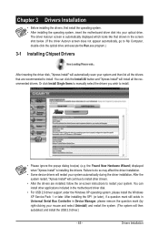
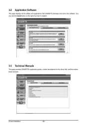
Drivers Installation - 66 - You can click the Install button on the right of an item to install it. 3-3 Technical Manuals This page provides GIGABYTE's application guides, content descriptions for this driver disk, and the motherboard manuals. 3-2 Application Software This page displays all the utilities and applications that GIGABYTE develops and some free software.
Drivers Installation - 66 - You can click the Install button on the right of an item to install it. 3-3 Technical Manuals This page provides GIGABYTE's application guides, content descriptions for this driver disk, and the motherboard manuals. 3-2 Application Software This page displays all the utilities and applications that GIGABYTE develops and some free software.
Manual
Page 72
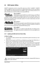
...or damaged, the backup BIOS will download the latest BIOS file from the hassles of system safety, users cannot update the backup BIOS manually. GIGABYTE Q-Flash and @BIOS are easy-to-use FAT32/16/12 file system. 3. For the sake of going through complicated BIOS flashing process... flashing may result in the Windows environment. @BIOS will take over on the main BIOS. p55aud4p.f1) to enter MS-DOS mode. Before You Begin 1. P55A-UD4P D20 . . . . : BIOS Setup : XpressRecovery2 : Boot Menu : Qflash 09/23/2009-P55-7A89RG0WC-00 Because BIOS flashing is Q-Flash™? Unique ...
...or damaged, the backup BIOS will download the latest BIOS file from the hassles of system safety, users cannot update the backup BIOS manually. GIGABYTE Q-Flash and @BIOS are easy-to-use FAT32/16/12 file system. 3. For the sake of going through complicated BIOS flashing process... flashing may result in the Windows environment. @BIOS will take over on the main BIOS. p55aud4p.f1) to enter MS-DOS mode. Before You Begin 1. P55A-UD4P D20 . . . . : BIOS Setup : XpressRecovery2 : Boot Menu : Qflash 09/23/2009-P55-7A89RG0WC-00 Because BIOS flashing is Q-Flash™? Unique ...
Manual
Page 75
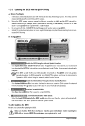
...a system that the BIOS file to be flashed matches your motherboard model. Updating the BIOS with the @BIOS Utility A. Do not use the G.O.M. (GIGABYTE Online Management) function when using @BIOS. 4. Update the BIOS Using the Internet Update Function: Click Update BIOS from the Internet or through other source... load BIOS defaults after BIOS update and after updating the BIOS. Before You Begin 1. Follow the on the @BIOS server site, please manually download the BIOS update file from an inadequate BIOS flashing. Make sure that is stable and do so may result in "Update the BIOS...
...a system that the BIOS file to be flashed matches your motherboard model. Updating the BIOS with the @BIOS Utility A. Do not use the G.O.M. (GIGABYTE Online Management) function when using @BIOS. 4. Update the BIOS Using the Internet Update Function: Click Update BIOS from the Internet or through other source... load BIOS defaults after BIOS update and after updating the BIOS. Before You Begin 1. Follow the on the @BIOS server site, please manually download the BIOS update file from an inadequate BIOS flashing. Make sure that is stable and do so may result in "Update the BIOS...


