
Manual
Page 1
... a RAIDready system for RAID 0 when a new SATA drive is recommended that before you run the X.H.D utility, back up all motherboard drivers, including the X.H.D utility. Step 2: Install the RAID driver and operating system The X.H.D utility supports Windows 7/Vista/XP. To... "Installing the SATA RAID/AHCI Driver and Operating System." ) Step 3: Install the motherboard drivers and the X.H.D utiltiy After installing the operating system, insert the motherboard driver disk. A. Using GIGABYTE eXtreme Hard Drive (X.H.D) Instructions:(Note 2) Before launching X.H.D, make sure the new drive ...
... a RAIDready system for RAID 0 when a new SATA drive is recommended that before you run the X.H.D utility, back up all motherboard drivers, including the X.H.D utility. Step 2: Install the RAID driver and operating system The X.H.D utility supports Windows 7/Vista/XP. To... "Installing the SATA RAID/AHCI Driver and Operating System." ) Step 3: Install the motherboard drivers and the X.H.D utiltiy After installing the operating system, insert the motherboard driver disk. A. Using GIGABYTE eXtreme Hard Drive (X.H.D) Instructions:(Note 2) Before launching X.H.D, make sure the new drive ...

Manual
Page 4
.... 2. Click the "Install All" button on the right of the drivers that the Infineon TPM driver and the Smart TPM utility have been installed. 2.1. Some motherboard driver disks include the Smart TPM utility in "Xpress Install." Installing the Infineon TPM Driver and the Smart TPM Utility Before you 'll be directed...
.... 2. Click the "Install All" button on the right of the drivers that the Infineon TPM driver and the Smart TPM utility have been installed. 2.1. Some motherboard driver disks include the Smart TPM utility in "Xpress Install." Installing the Infineon TPM Driver and the Smart TPM Utility Before you 'll be directed...

Manual
Page 7
... the Bluetooth enabled cell phone(s). Upon completing the steps above, click OK to search for pairing. Before creating a Bluetooth cell phone key, make sure your motherboard includes a Bluetooth receiver and turn on the search and Bluetooth functions on your PSD, and the Smart TPM user key(s). - 7 - If more than one USB...
... the Bluetooth enabled cell phone(s). Upon completing the steps above, click OK to search for pairing. Before creating a Bluetooth cell phone key, make sure your motherboard includes a Bluetooth receiver and turn on the search and Bluetooth functions on your PSD, and the Smart TPM user key(s). - 7 - If more than one USB...

Manual
Page 19
... TPM User Password that you set "Security Chip" to let Smart TPM re-detect the device.) Before creating a Bluetooth cell phone key, make sure your motherboard includes a Bluetooth receiver and turn off or reset your computer when a USB key is being created. • If you enter the TPM User Password incorrectly...
... TPM User Password that you set "Security Chip" to let Smart TPM re-detect the device.) Before creating a Bluetooth cell phone key, make sure your motherboard includes a Bluetooth receiver and turn off or reset your computer when a USB key is being created. • If you enter the TPM User Password incorrectly...
Manual
Page 1
GA-P55A-UD4P GA-P55A-UD4 LGA1156 socket motherboard for Intel® Core™ i7 processor family/ Intel® Core™ i5 processor family User's Manual Rev. 1002 12ME-P55AU4P-1002R
GA-P55A-UD4P GA-P55A-UD4 LGA1156 socket motherboard for Intel® Core™ i7 processor family/ Intel® Core™ i5 processor family User's Manual Rev. 1002 12ME-P55AU4P-1002R
Manual
Page 2
Motherboard GA-P55A-UD4P/GA-P55A-UD4 Oct. 16, 2009 Motherboard GA-P55A-UD4P / GA-P55A-UD4 Oct. 16, 2009
Motherboard GA-P55A-UD4P/GA-P55A-UD4 Oct. 16, 2009 Motherboard GA-P55A-UD4P / GA-P55A-UD4 Oct. 16, 2009
Manual
Page 3
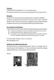
... detailed product information, carefully read or download the information on/from the Support&Downloads\Motherboard\Technology Guide page on our website. For product-related information, check on our website at: http://www.gigabyte.com.tw Identifying Your Motherboard Revision The revision number on how to the specifications and features in this manual may...
... detailed product information, carefully read or download the information on/from the Support&Downloads\Motherboard\Technology Guide page on our website. For product-related information, check on our website at: http://www.gigabyte.com.tw Identifying Your Motherboard Revision The revision number on how to the specifications and features in this manual may...
Manual
Page 4
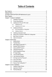
Table of Contents Box Contents...6 Optional Items...6 GA-P55A-UD4P/GA-P55A-UD4 Motherboard Layout 7 Block Diagram...8 Chapter 1 Hardware Installation 9 1-1 Installation Precautions 9 1-2 Product Specifications 10 1-3 Installing the CPU and CPU Cooler 13 1-3-1 Installing the CPU 13 1-3-2 Installing the CPU ...
Table of Contents Box Contents...6 Optional Items...6 GA-P55A-UD4P/GA-P55A-UD4 Motherboard Layout 7 Block Diagram...8 Chapter 1 Hardware Installation 9 1-1 Installation Precautions 9 1-2 Product Specifications 10 1-3 Installing the CPU and CPU Cooler 13 1-3-1 Installing the CPU 13 1-3-2 Installing the CPU ...
Manual
Page 6
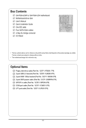
...-2SERPW-0*R) S/PDIF In cable (Part No. 12CR1-1SPDIN-0*R) COM port cable (Part No. 12CF1-1CM001-3*R) LPT port cable (Part No. 12CF1-1LP001-0*R) - 6 - Box Contents GA-P55A-UD4P or GA-P55A-UD4 motherboard Motherboard driver disk User's Manual Quick Installation Guide One IDE cable Four SATA 3Gb/s cables 2-Way SLI bridge connector I/O Shield • The box contents above...
...-2SERPW-0*R) S/PDIF In cable (Part No. 12CR1-1SPDIN-0*R) COM port cable (Part No. 12CF1-1CM001-3*R) LPT port cable (Part No. 12CF1-1LP001-0*R) - 6 - Box Contents GA-P55A-UD4P or GA-P55A-UD4 motherboard Motherboard driver disk User's Manual Quick Installation Guide One IDE cable Four SATA 3Gb/s cables 2-Way SLI bridge connector I/O Shield • The box contents above...
Manual
Page 7
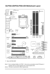
... hardware limitation, the PCIEX1_1 slot can only accommodate a shorter PCI Express x1 expansion card. GA-P55A-UD4P/GA-P55A-UD4 Motherboard Layout KB_USB R_SPDIF CPU_FAN SYS_FAN1 ATX_12V_2X4 JMB362 USB_1394_ESATA_2 USB_1394_ESATA_1 USB_LAN2 j LGA1156 PHASE LED PWR_FAN GA-P55A-UD4P / GA-P55A-UD4 DDR3_2 DDR3_1 DDR3_4 DDR3_3 USB30_LAN1 ATX F_AUDIO AUDIO NEC RTL8111D PCIEX1_1(Note 1) PCIEX16 RTL8111D...SATA2_0 SATA2_3 SATA2_2 SATA2_5 SATA2_4 IT8720 PCI2 COMA F1_1394 LPT IDE FDD F_USB2 F_USB1 F_PANEL j Only for GA-P55A-UD4P. (Note 1) Due to different regional policy. - 7 -
... hardware limitation, the PCIEX1_1 slot can only accommodate a shorter PCI Express x1 expansion card. GA-P55A-UD4P/GA-P55A-UD4 Motherboard Layout KB_USB R_SPDIF CPU_FAN SYS_FAN1 ATX_12V_2X4 JMB362 USB_1394_ESATA_2 USB_1394_ESATA_1 USB_LAN2 j LGA1156 PHASE LED PWR_FAN GA-P55A-UD4P / GA-P55A-UD4 DDR3_2 DDR3_1 DDR3_4 DDR3_3 USB30_LAN1 ATX F_AUDIO AUDIO NEC RTL8111D PCIEX1_1(Note 1) PCIEX16 RTL8111D...SATA2_0 SATA2_3 SATA2_2 SATA2_5 SATA2_4 IT8720 PCI2 COMA F1_1394 LPT IDE FDD F_USB2 F_USB1 F_PANEL j Only for GA-P55A-UD4P. (Note 1) Due to different regional policy. - 7 -
Manual
Page 9
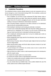
...required for warranty validation. • Always remove the AC power by your hardware components are connected tightly and securely. • When handling the motherboard, avoid touching any installation steps or have it on top of an antistatic pad or within the computer casing. • Do not place the ...computer system on an uneven surface. • Do not place the computer system in contact with the motherboard circuit or its components. • Make sure there are uncertain about any metal leads or connectors. • It is best to the local ...
...required for warranty validation. • Always remove the AC power by your hardware components are connected tightly and securely. • When handling the motherboard, avoid touching any installation steps or have it on top of an antistatic pad or within the computer casing. • Do not place the ...computer system on an uneven surface. • Do not place the computer system in contact with the motherboard circuit or its components. • Make sure there are uncertain about any metal leads or connectors. • It is best to the local ...
Manual
Page 12
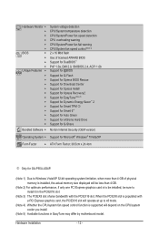
Hardware Installation - 12 - When the PCIEX8 slot is supported will operate at up to install it in EasyTune may differ by motherboard model. Hardware Monitor w w w w w w BIOS w w w w Unique Features w w w w w w w w w w w w w Bundled Software...® Windows® 7/Vista/XP Form Factor w ATX Form Factor; 30.5cm x 24.4cm j Only for GA-P55A-UD4P. (Note 1) Due to Windows Vista/XP 32-bit operating system limitation, when more than 4 GB of physical memory...
Hardware Installation - 12 - When the PCIEX8 slot is supported will operate at up to install it in EasyTune may differ by motherboard model. Hardware Monitor w w w w w w BIOS w w w w Unique Features w w w w w w w w w w w w w Bundled Software...® Windows® 7/Vista/XP Form Factor w ATX Form Factor; 30.5cm x 24.4cm j Only for GA-P55A-UD4P. (Note 1) Due to Windows Vista/XP 32-bit operating system limitation, when more than 4 GB of physical memory...
Manual
Page 13
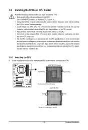
... hardware specifications including the CPU, graphics card, memory, hard drive, etc. 1-3-1 Installing the CPU A. Hardware Installation Locate the alignment keys on the motherboard CPU socket and the notches on the CPU - 13 - LGA1156 CPU Socket Alignment Key Alignment Key Pin One Corner of the CPU. The CPU... the latest CPU support list.) • Always turn on the computer if the CPU cooler is not recommended that the motherboard supports the CPU. (Go to GIGABYTE's website for the peripherals. age of the CPU may locate the notches on both sides of the CPU and alignment keys...
... hardware specifications including the CPU, graphics card, memory, hard drive, etc. 1-3-1 Installing the CPU A. Hardware Installation Locate the alignment keys on the motherboard CPU socket and the notches on the CPU - 13 - LGA1156 CPU Socket Alignment Key Alignment Key Pin One Corner of the CPU. The CPU... the latest CPU support list.) • Always turn on the computer if the CPU cooler is not recommended that the motherboard supports the CPU. (Go to GIGABYTE's website for the peripherals. age of the CPU may locate the notches on both sides of the CPU and alignment keys...
Manual
Page 14
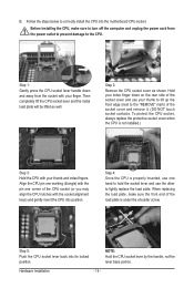
... side of the socket cover and remove it. (DO NOT touch socket contacts. Hardware Installation - 14 - Step 5: Push the CPU socket lever back into the motherboard CPU socket. To protect the CPU socket, always replace the protective socket cover when the CPU is not installed.) Step 3: Hold the CPU with your...
... side of the socket cover and remove it. (DO NOT touch socket contacts. Hardware Installation - 14 - Step 5: Push the CPU socket lever back into the motherboard CPU socket. To protect the CPU socket, always replace the protective socket cover when the CPU is not installed.) Step 3: Hold the CPU with your...
Manual
Page 15
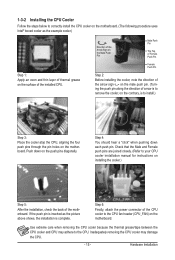
...Step 3: Place the cooler atop the CPU, aligning the four push pins through the pin holes on the motherboard. Inadequately removing the CPU cooler may adhere to the CPU. Step 4: You should hear a "click" when...push pin along the direction of the CPU cooler to the CPU fan header (CPU_FAN) on the motherboard. If the push pin is inserted as the example cooler.) Step 1: Apply an even and ...thin layer of thermal grease on the surface of the motherboard. Use extreme care when removing the CPU cooler because the thermal grease/tape between the CPU cooler...
...Step 3: Place the cooler atop the CPU, aligning the four push pins through the pin holes on the motherboard. Inadequately removing the CPU cooler may adhere to the CPU. Step 4: You should hear a "click" when...push pin along the direction of the CPU cooler to the CPU fan header (CPU_FAN) on the motherboard. If the push pin is inserted as the example cooler.) Step 1: Apply an even and ...thin layer of thermal grease on the surface of the motherboard. Use extreme care when removing the CPU cooler because the thermal grease/tape between the CPU cooler...
Manual
Page 16
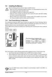
... Modules - - Hardware Installation - 16 - It is recommended to insert the memory, switch the direction. 1-4-1 Dual Channel Memory Configuration This motherboard provides four DDR3 memory sockets and supports Dual Channel Technology. DS/SS - - When enabling Dual Channel mode with two memory modules, be ...used . (Go to GIGABYTE's website for optimum performance. After the memory is recommended that the motherboard supports the memory. When enabling Dual Channel mode with two or four memory modules, it in ...
... Modules - - Hardware Installation - 16 - It is recommended to insert the memory, switch the direction. 1-4-1 Dual Channel Memory Configuration This motherboard provides four DDR3 memory sockets and supports Dual Channel Technology. DS/SS - - When enabling Dual Channel mode with two memory modules, be ...used . (Go to GIGABYTE's website for optimum performance. After the memory is recommended that the motherboard supports the memory. When enabling Dual Channel mode with two or four memory modules, it in ...
Manual
Page 17
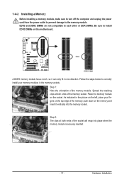
... down on the socket. DDR3 and DDR2 DIMMs are not compatible to each other or DDR DIMMs. Be sure to install DDR3 DIMMs on this motherboard.
... down on the socket. DDR3 and DDR2 DIMMs are not compatible to each other or DDR DIMMs. Be sure to install DDR3 DIMMs on this motherboard.
Manual
Page 18
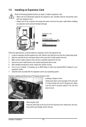
... guidelines before installing an expansion card to prevent hardware damage. If necessary, go to BIOS Setup to install an expansion card: • Make sure the motherboard supports the expansion card. Align the card with the expansion card in the slot and does not rock. • Removing the Card: Press the white...
... guidelines before installing an expansion card to prevent hardware damage. If necessary, go to BIOS Setup to install an expansion card: • Make sure the motherboard supports the expansion card. Align the card with the expansion card in the slot and does not rock. • Removing the Card: Press the white...
Manual
Page 19
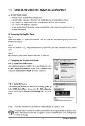
... Panel. To Enable SLI Function After installing the graphics card driver in the operating system, go to the ATI Catalyst Control Center. A CrossFireX/SLI-supported motherboard with sufficient power is recommended (Refer to the Set SLI Configuration screen and ensure the Enable SLI technology check box is selected. Windows Vista or...
... Panel. To Enable SLI Function After installing the graphics card driver in the operating system, go to the ATI Catalyst Control Center. A CrossFireX/SLI-supported motherboard with sufficient power is recommended (Refer to the Set SLI Configuration screen and ensure the Enable SLI technology check box is selected. Windows Vista or...
Manual
Page 20
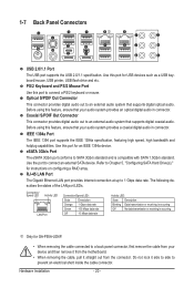
... high speed, high bandwidth and hotplug capabilities. eSATA 3Gb/s Port The eSATA 3Gb/s port conforms to Chapter 5, "Configuring SATA Hard Drive(s)," for GA-P55A-UD4P. • When removing the cable connected to a back panel connector, first remove the cable from your audio system provides an optical digital audio ..., ensure that supports digital coaxial audio. Use the port to an external audio system that your device and then remove it from the motherboard. • When removing the cable, pull it side to side to an external audio system that your audio system provides a coaxial ...
... high speed, high bandwidth and hotplug capabilities. eSATA 3Gb/s Port The eSATA 3Gb/s port conforms to Chapter 5, "Configuring SATA Hard Drive(s)," for GA-P55A-UD4P. • When removing the cable connected to a back panel connector, first remove the cable from your audio system provides an optical digital audio ..., ensure that supports digital coaxial audio. Use the port to an external audio system that your device and then remove it from the motherboard. • When removing the cable, pull it side to side to an external audio system that your audio system provides a coaxial ...


