
Manual
Page 7
... ATX_12V GA-P55-USB3L PHASE LED LGA1156 PWR_FAN R_USB ATX USB30_LAN AUDIO F_AUDIO NEC D720200F1 SYS_FAN1 PCIEX1_1 (Note) CPU_FAN DDR3_2 DDR3_1 DDR3_4 DDR3_3 RTL8111D CODEC SPDIF_O CD_IN SPDIF_I PCIEX16 PCIEX1_2 PCI1 PCI2 PCI3 SYS_FAN2 BAT Intel® P55/H55 SATA2_0 SATA2_1 SATA2_2 SATA2_5 SATA2_4SATA2_3 IDE IT8720 B_BIOS M_BIOS FDD PCIEX4_X1 F_USB3j F_USB1 F_USB2 GSATA2_6 CLR_CMOS GIGABYTE...
... ATX_12V GA-P55-USB3L PHASE LED LGA1156 PWR_FAN R_USB ATX USB30_LAN AUDIO F_AUDIO NEC D720200F1 SYS_FAN1 PCIEX1_1 (Note) CPU_FAN DDR3_2 DDR3_1 DDR3_4 DDR3_3 RTL8111D CODEC SPDIF_O CD_IN SPDIF_I PCIEX16 PCIEX1_2 PCI1 PCI2 PCI3 SYS_FAN2 BAT Intel® P55/H55 SATA2_0 SATA2_1 SATA2_2 SATA2_5 SATA2_4SATA2_3 IDE IT8720 B_BIOS M_BIOS FDD PCIEX4_X1 F_USB3j F_USB1 F_USB2 GSATA2_6 CLR_CMOS GIGABYTE...
Manual
Page 8
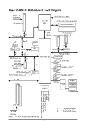
GA-P55-USB3L Motherboard Block Diagram PCIe CLK (100 MHz) 1 PCI Express x16 LGA1156 CPU CPU CLK+/- (133 MHz) DDR3 2200/1333/1066/800 MHz Dual Channel Memory ... (PCIEX1_1) 2 SATA 3Gb/s ATA-133/100/66/33 IDE Channel PCI Bus 2 USB 3.0 NEC D720200F1 Intel® P55/H55 x4j/X1k x1 Switchj PCI Express Bus Dual BIOS 6 SATA 3Gb/s x1 14 USB 2.0/1.1j (Note) GIGABYTE SATA2 12 USB 2.0/1.1k (Note) CODEC LPC Bus IT8720 Floppy COM Port PS/2 KB/Mouse MIC (Center...
GA-P55-USB3L Motherboard Block Diagram PCIe CLK (100 MHz) 1 PCI Express x16 LGA1156 CPU CPU CLK+/- (133 MHz) DDR3 2200/1333/1066/800 MHz Dual Channel Memory ... (PCIEX1_1) 2 SATA 3Gb/s ATA-133/100/66/33 IDE Channel PCI Bus 2 USB 3.0 NEC D720200F1 Intel® P55/H55 x4j/X1k x1 Switchj PCI Express Bus Dual BIOS 6 SATA 3Gb/s x1 14 USB 2.0/1.1j (Note) GIGABYTE SATA2 12 USB 2.0/1.1k (Note) CODEC LPC Bus IT8720 Floppy COM Port PS/2 KB/Mouse MIC (Center...
Manual
Page 10
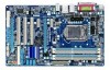
...174; Core™ i3 series processor in the LGA1156 package (Go to GIGABYTE's website for the latest CPU support list.) L3 cache varies with CPU Chipset Intel® P55/H55 Express Chipset Memory Audio 4 x 1.5V DDR3 DIMM sockets supporting... 2 x PCI Express x1 slots 3 x PCI slots Multi-Graphics Support for P55 chipset. Support for H55 chipset. k Only for SATA RAID 0, RAID 1, RAID 5, and RAID 10j GIGABYTE SATA2 chip: - 1 x IDE connector supporting ATA-133/100/66/33 and up to 2 IDE devices -...
...174; Core™ i3 series processor in the LGA1156 package (Go to GIGABYTE's website for the latest CPU support list.) L3 cache varies with CPU Chipset Intel® P55/H55 Express Chipset Memory Audio 4 x 1.5V DDR3 DIMM sockets supporting... 2 x PCI Express x1 slots 3 x PCI slots Multi-Graphics Support for P55 chipset. Support for H55 chipset. k Only for SATA RAID 0, RAID 1, RAID 5, and RAID 10j GIGABYTE SATA2 chip: - 1 x IDE connector supporting ATA-133/100/66/33 and up to 2 IDE devices -...

Manual
Page 11
k Only for P55 chipset. Hardware Installation Up to 12 USB 2.0/1.1 ports (Note 6) (8 on the back panel Internal w 1 x 24-pin ATX main power connector Connectors w 1 x 4-pin ATX 12V power ... temperature detection CPU/System/Power fan speed detection CPU overheating warning CPU/System/Power fan fail warning CPU/System fan speed control (Note 7) j Only for H55 chipset. - 11 - Up to 2 USB 3.0 ports on the back panel, 4 via the USB brackets connected to the internal USB headers) k NEC D720200F1 chip: - Up...
k Only for P55 chipset. Hardware Installation Up to 12 USB 2.0/1.1 ports (Note 6) (8 on the back panel Internal w 1 x 24-pin ATX main power connector Connectors w 1 x 4-pin ATX 12V power ... temperature detection CPU/System/Power fan speed detection CPU overheating warning CPU/System/Power fan fail warning CPU/System fan speed control (Note 7) j Only for H55 chipset. - 11 - Up to 2 USB 3.0 ports on the back panel, 4 via the USB brackets connected to the internal USB headers) k NEC D720200F1 chip: - Up...
Manual
Page 24
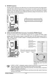
The P55 Chipset supports RAID 0, RAID 1, RAID 5, and RAID 10. Before attaching the IDE cable, locate the foolproof groove on configuring a RAID array. 7 1 SATA2_0 Pin No. If ... to Chapter 5, "Configuring SATA Hard Drive(s)," for the IDE devices, read the instructions from the device manufacturers.) 39 1 40 2 8) SATA2_0/1/2/3/4/5 (SATA 3Gb/s Connectors, Controlled by P55/H55 Chipset) The SATA connectors conform to two IDE devices such as hard drives and optical drives.
The P55 Chipset supports RAID 0, RAID 1, RAID 5, and RAID 10. Before attaching the IDE cable, locate the foolproof groove on configuring a RAID array. 7 1 SATA2_0 Pin No. If ... to Chapter 5, "Configuring SATA Hard Drive(s)," for the IDE devices, read the instructions from the device manufacturers.) 39 1 40 2 8) SATA2_0/1/2/3/4/5 (SATA 3Gb/s Connectors, Controlled by P55/H55 Chipset) The SATA connectors conform to two IDE devices such as hard drives and optical drives.
Manual
Page 49
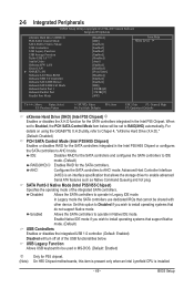
.... USB Legacy Function Allows USB keyboard to be set to AHCI mode. Disabled Allows the SATA controllers to operate in the Intel P55/H55 Chipset or configures the SATA controllers to Enabled, the PCH SATA Control Mode item below will turn off all of the integrated SATA... controllers. For details on using the GIGABYTE X.H.D utility, refer to enable advanced Serial ATA features such as Native Command Queuing and hot plug. Advanced Host Controller Interface (AHCI) is ...
.... USB Legacy Function Allows USB keyboard to be set to AHCI mode. Disabled Allows the SATA controllers to operate in the Intel P55/H55 Chipset or configures the SATA controllers to Enabled, the PCH SATA Control Mode item below will turn off all of the integrated SATA... controllers. For details on using the GIGABYTE X.H.D utility, refer to enable advanced Serial ATA features such as Native Command Queuing and hot plug. Advanced Host Controller Interface (AHCI) is ...

Manual
Page 50
... fields show 0m, as shown in network card instead of wires will appear: Start detecting at Port..... Link Detected --> 100Mbps Cable Length= 30m (Note) On H55 Chipset motherboards, this item is present only when an Intel Lynnfield CPU is attached to the motherboard, the Status fields of all four pairs of...
... fields show 0m, as shown in network card instead of wires will appear: Start detecting at Port..... Link Detected --> 100Mbps Cable Length= 30m (Note) On H55 Chipset motherboards, this item is present only when an Intel Lynnfield CPU is attached to the motherboard, the Status fields of all four pairs of...
