Manual
Page 19
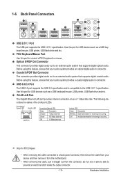
... is compatible to a back panel connector, first remove the cable from your audio system provides an optical digital audio in connector. Use this port for P55 Chipset. • When removing the cable connected to the USB 2.0/1.1 specification. Hardware Installation Before using this port to 1 Gbps data rate. Do not ... Use this feature, ensure that supports digital coaxial audio. Optical S/PDIF Out Connector This connector provides digital audio out to prevent an electrical short inside the cable connector. - 19 - The following describes the states of the LAN port LEDs.
... is compatible to a back panel connector, first remove the cable from your audio system provides an optical digital audio in connector. Use this port for P55 Chipset. • When removing the cable connected to the USB 2.0/1.1 specification. Hardware Installation Before using this port to 1 Gbps data rate. Do not ... Use this feature, ensure that supports digital coaxial audio. Optical S/PDIF Out Connector This connector provides digital audio out to prevent an electrical short inside the cable connector. - 19 - The following describes the states of the LAN port LEDs.
Manual
Page 25
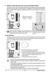
... (+) and the negative side (-) of the battery holder, making them short for 5 seconds.) 3. Please connect the L-shaped end of the SATA 3Gb/s cable to your computer and unplug the power cord. 2. The GIGABYTE SATA2 controller supports RAID 0, RAID 1, and JBOD. 9) GSATA2_6/7 (...SATA 3Gb/s Connectors, Controlled by GIGABYTE SATA2) The SATA connectors conform to Chapter 5, "Configuring SATA Hard Drive(s)," for instructions on configuring...
... (+) and the negative side (-) of the battery holder, making them short for 5 seconds.) 3. Please connect the L-shaped end of the SATA 3Gb/s cable to your computer and unplug the power cord. 2. The GIGABYTE SATA2 controller supports RAID 0, RAID 1, and JBOD. 9) GSATA2_6/7 (...SATA 3Gb/s Connectors, Controlled by GIGABYTE SATA2) The SATA connectors conform to Chapter 5, "Configuring SATA Hard Drive(s)," for instructions on configuring...

Manual
Page 26
... (Hard Drive Activity LED, Blue) Connects to the reset switch on the chassis front panel. The system reports system startup status by chassis. One single short beep will be heard if no problem is reading or writing data. • RES (Reset Switch, Green): Connects to the hard drive activity LED on...
... (Hard Drive Activity LED, Blue) Connects to the reset switch on the chassis front panel. The system reports system startup status by chassis. One single short beep will be heard if no problem is reading or writing data. • RES (Reset Switch, Green): Connects to the hard drive activity LED on...

Manual
Page 30
... cap from the power outlet before clearing the CMOS values. • After clearing the CMOS values and before turning on the two pins to temporarily short the two pins or use a metal object like a screwdriver to Chapter 2, "BIOS Setup," for a few seconds. Hardware Installation - 30 - date information and BIOS configurations) and...
... cap from the power outlet before clearing the CMOS values. • After clearing the CMOS values and before turning on the two pins to temporarily short the two pins or use a metal object like a screwdriver to Chapter 2, "BIOS Setup," for a few seconds. Hardware Installation - 30 - date information and BIOS configurations) and...
Manual
Page 51
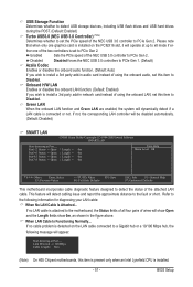
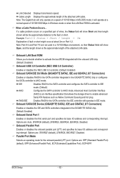
... Port..... USB Storage Function Determines whether to detect USB storage devices, including USB flash drives and USB hard drives during the POST. (Default: Enabled) Turbo USB3.0 (NEC USB 3.0 Controller) (Note) Determines whether to set this item to Disabled. Disabled Disabled forces the NEC USB 3.0 controllers to PCIe Gen 1. (...to install a 3rd party add-in audio card instead of the two controllers is installed on the LAN cable connected to the fault or short. Refer to Disabled. If no cable problem is detected on the PCIEX16 slot, it will operate at up to x8 mode if either ...
... Port..... USB Storage Function Determines whether to detect USB storage devices, including USB flash drives and USB hard drives during the POST. (Default: Enabled) Turbo USB3.0 (NEC USB 3.0 Controller) (Note) Determines whether to set this item to Disabled. Disabled Disabled forces the NEC USB 3.0 controllers to PCIe Gen 1. (...to install a 3rd party add-in audio card instead of the two controllers is installed on the LAN cable connected to the fault or short. Refer to Disabled. If no cable problem is detected on the PCIEX16 slot, it will operate at up to x8 mode if either ...
Manual
Page 52
... If a cable problem occurs on Part 1-2. Options are not used in a 10/100 Mbps environment, so their Status fields will show Short and then length shown will show Open, and the length shown is the approximate length of 10/100 Mbps in MS-DOS mode; Note:...) Onboard USB 3.0 Controller (NEC USB 3.0 Controller) Enables or disables the NEC USB 3.0 controller. (Default: Enabled) Onboard SATA/IDE Ctrl Mode (GIGABYTE SATA2, IDE and GSATA2_6/7 Connectors) Enables or disables RAID for the SATA controller and configures the SATA controller to IDE mode. (Default) AHCI Configures the...
... If a cable problem occurs on Part 1-2. Options are not used in a 10/100 Mbps environment, so their Status fields will show Short and then length shown will show Open, and the length shown is the approximate length of 10/100 Mbps in MS-DOS mode; Note:...) Onboard USB 3.0 Controller (NEC USB 3.0 Controller) Enables or disables the NEC USB 3.0 controller. (Default: Enabled) Onboard SATA/IDE Ctrl Mode (GIGABYTE SATA2, IDE and GSATA2_6/7 Connectors) Enables or disables RAID for the SATA controller and configures the SATA controller to IDE mode. (Default) AHCI Configures the...

Manual
Page 114
...GIGABYTE's website to show the advanced options. A: The following Award BIOS beep code descriptions may help you identify possible computer problems. (For reference only.) 1 short: System boots successfully 1 long, 3 short: Keyboard error 2 short: CMOS setting error 1 long, 9 short: BIOS ROM error 1 long, 1 short... Chapter 1. 5-3 Troubleshooting 5-3-1 Frequently Asked Questions To read more details, go to the Support&Downloads\Motherboard\FAQ page on GIGABYTE's website. You can temporarily remove the battery from Microsoft's website. Q: How do the beeps emitted during the POST. ...
...GIGABYTE's website to show the advanced options. A: The following Award BIOS beep code descriptions may help you identify possible computer problems. (For reference only.) 1 short: System boots successfully 1 long, 3 short: Keyboard error 2 short: CMOS setting error 1 long, 9 short: BIOS ROM error 1 long, 1 short... Chapter 1. 5-3 Troubleshooting 5-3-1 Frequently Asked Questions To read more details, go to the Support&Downloads\Motherboard\FAQ page on GIGABYTE's website. You can temporarily remove the battery from Microsoft's website. Q: How do the beeps emitted during the POST. ...
Manual
Page 115
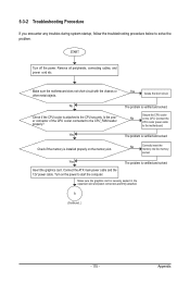
Yes Isolate the short circuit. No Check if the CPU cooler is verified and solved. Turn on the memory slot. Connect the CPU cooler power cable to the CPU_FAN ... connected to the motherboard. The problem is verified and solved. Yes The problem is verified and solved. A (Continued...) - 115 - Make sure the motherboard does not short-circuit with the chassis or other metal objects. Insert the graphics card. Check if the memory is securely seated in the expansion slot and power...
Yes Isolate the short circuit. No Check if the CPU cooler is verified and solved. Turn on the memory slot. Connect the CPU cooler power cable to the CPU_FAN ... connected to the motherboard. The problem is verified and solved. Yes The problem is verified and solved. A (Continued...) - 115 - Make sure the motherboard does not short-circuit with the chassis or other metal objects. Insert the graphics card. Check if the memory is securely seated in the expansion slot and power...


