Manual
Page 4
Table of Contents Box Contents...6 Optional Items...6 GA-P55-USB3 Motherboard Layout 7 GA-P55-USB3 Motherboard Block Diagram 8 Chapter 1 Hardware Installation 9 1-1 Installation Precautions 9 1-2 Product Specifications 10 1-3 Installing the CPU and CPU Cooler 13 1-3-1 Installing the CPU 13 1-3-2 Installing the CPU Cooler 15 1-4 Installing the Memory 16 1-4-1 Dual Channel Memory Configuration 16 1-4-2 Installing a Memory 17 1-5 Installing an Expansion Card 18 1-6 Back Panel...
Table of Contents Box Contents...6 Optional Items...6 GA-P55-USB3 Motherboard Layout 7 GA-P55-USB3 Motherboard Block Diagram 8 Chapter 1 Hardware Installation 9 1-1 Installation Precautions 9 1-2 Product Specifications 10 1-3 Installing the CPU and CPU Cooler 13 1-3-1 Installing the CPU 13 1-3-2 Installing the CPU Cooler 15 1-4 Installing the Memory 16 1-4-1 Dual Channel Memory Configuration 16 1-4-2 Installing a Memory 17 1-5 Installing an Expansion Card 18 1-6 Back Panel...

Manual
Page 8
GA-P55-USB3 Motherboard Block Diagram PCIe CLK (100 MHz) 1 PCI Express x16 LGA1156 CPU CPU CLK+/- (133 MHz) DDR3 2200/1333/1066/800 MHz Dual Channel Memory PCI Express Bus x16 LAN Gen 2 ...2 USB 3.0 x1 x4j/X1k Switchj NEC PCI Express Bus Dual BIOS Intel® P55/H55 6 SATA 3Gb/s x1 14 USB 2.0/1.1j (Note) 2 SATA 3Gb/s ATA-133/100/66/33 IDE Channel GIGABYTE SATA2 12 USB 2.0/1.1k (Note) PCI Bus LPC Bus Floppy CODEC IT8720 COM Port...In S/PDIF Out 3 PCI PCI CLK (33 MHz) (Note) Two share the same ports with USB 3.0. - 8 - k Only for P55 Chipset. j Only for H55 Chipset.
GA-P55-USB3 Motherboard Block Diagram PCIe CLK (100 MHz) 1 PCI Express x16 LGA1156 CPU CPU CLK+/- (133 MHz) DDR3 2200/1333/1066/800 MHz Dual Channel Memory PCI Express Bus x16 LAN Gen 2 ...2 USB 3.0 x1 x4j/X1k Switchj NEC PCI Express Bus Dual BIOS Intel® P55/H55 6 SATA 3Gb/s x1 14 USB 2.0/1.1j (Note) 2 SATA 3Gb/s ATA-133/100/66/33 IDE Channel GIGABYTE SATA2 12 USB 2.0/1.1k (Note) PCI Bus LPC Bus Floppy CODEC IT8720 COM Port...In S/PDIF Out 3 PCI PCI CLK (33 MHz) (Note) Two share the same ports with USB 3.0. - 8 - k Only for P55 Chipset. j Only for H55 Chipset.
Manual
Page 9
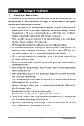
... eliminate static electricity. • Prior to installing the motherboard, please have it on the computer power during the installation process can become damaged as a motherboard, CPU or memory. Chapter 1 Hardware Installation 1-1 Installation Precautions The motherboard contains numerous delicate electronic circuits and components which can lead to damage to system components as...
... eliminate static electricity. • Prior to installing the motherboard, please have it on the computer power during the installation process can become damaged as a motherboard, CPU or memory. Chapter 1 Hardware Installation 1-1 Installation Precautions The motherboard contains numerous delicate electronic circuits and components which can lead to damage to system components as...

Manual
Page 10
... processor/Intel® Core™ i5 series processor in the LGA1156 package (Go to GIGABYTE's website for the latest CPU support list.) L3 cache varies with CPU Chipset Intel® P55/H55 Express Chipset Memory Audio 4 x 1.5V DDR3 DIMM sockets supporting up ... MHz memory modules Support for non-ECC memory modules Support for Extreme Memory Profile (XMP) memory modules (Go to GIGABYTE's website for the latest memory support list.) Realtek ALC888 codec High Definition Audio 2/4/5.1/7.1-channel Support ...
... processor/Intel® Core™ i5 series processor in the LGA1156 package (Go to GIGABYTE's website for the latest CPU support list.) L3 cache varies with CPU Chipset Intel® P55/H55 Express Chipset Memory Audio 4 x 1.5V DDR3 DIMM sockets supporting up ... MHz memory modules Support for non-ECC memory modules Support for Extreme Memory Profile (XMP) memory modules (Go to GIGABYTE's website for the latest memory support list.) Realtek ALC888 codec High Definition Audio 2/4/5.1/7.1-channel Support ...
Manual
Page 11
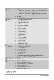
k Only for P55 Chipset. Up to the internal USB headers) j - Hardware Installation USB Chipset: - Up to 14 USB 2.0/1.1 ports (...panel Internal w 1 x 24-pin ATX main power connector Connectors w 1 x 8-pin ATX 12V power connector w 1 x floppy disk drive connector w 1 x IDE connector w 8 x SATA 3Gb/s connectors w 1 x CPU fan header w 2 x system fan headers w 1 x power fan header w 1 x front panel header w 1 x front panel audio header w 1 x CD In connector w 1 x S/PDIF In header w 1 ...
k Only for P55 Chipset. Up to the internal USB headers) j - Hardware Installation USB Chipset: - Up to 14 USB 2.0/1.1 ports (...panel Internal w 1 x 24-pin ATX main power connector Connectors w 1 x 8-pin ATX 12V power connector w 1 x floppy disk drive connector w 1 x IDE connector w 8 x SATA 3Gb/s connectors w 1 x CPU fan header w 2 x system fan headers w 1 x power fan header w 1 x front panel header w 1 x front panel audio header w 1 x CD In connector w 1 x S/PDIF In header w 1 ...
Manual
Page 12
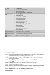
...) Operating System w Support for Microsoft® Windows® 7/Vista/XP Form Factor w ATX Form Factor; 30.5cm x 24.4cm j Only for P55 Chipset. (Note 1) Due to Windows 32-bit operating system limitation, when more than 4 GB of physical memory is installed, the actual memory size displayed...at up to x4 mode when ATI CrossFireX is enabled. (Note 5) Two share the same ports with USB 3.0. (Note 6) Whether the CPU/system fan speed control function is supported will depend on the CPU/system cooler you install. (Note 7) Available functions in EasyTune may differ by motherboard model.
...) Operating System w Support for Microsoft® Windows® 7/Vista/XP Form Factor w ATX Form Factor; 30.5cm x 24.4cm j Only for P55 Chipset. (Note 1) Due to Windows 32-bit operating system limitation, when more than 4 GB of physical memory is installed, the actual memory size displayed...at up to x4 mode when ATI CrossFireX is enabled. (Note 5) Two share the same ports with USB 3.0. (Note 6) Whether the CPU/system fan speed control function is supported will depend on the CPU/system cooler you install. (Note 7) Available functions in EasyTune may differ by motherboard model.
Manual
Page 13
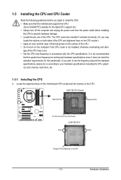
...specifications, please do so according to prevent hardware damage. • Locate the pin one of the CPU. LGA1156 CPU Socket Alignment Key Alignment Key Pin One Corner of the CPU. • Do not turn off the computer and unplug the power cord from the power outlet ...hardware specifications since it does not meet the standard requirements for the latest CPU support list.) • Always turn on the computer if the CPU cooler is not recommended that the motherboard supports the CPU. (Go to GIGABYTE's website for the peripherals. It is not installed, otherwise overheating and...
...specifications, please do so according to prevent hardware damage. • Locate the pin one of the CPU. LGA1156 CPU Socket Alignment Key Alignment Key Pin One Corner of the CPU. • Do not turn off the computer and unplug the power cord from the power outlet ...hardware specifications since it does not meet the standard requirements for the latest CPU support list.) • Always turn on the computer if the CPU cooler is not recommended that the motherboard supports the CPU. (Go to GIGABYTE's website for the peripherals. It is not installed, otherwise overheating and...
Manual
Page 14
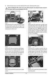
... your index finger down and away from the power outlet to prevent damage to the "REMOVE" mark) of the CPU socket (or you may align the CPU notches with your finger. Step 4: Once the CPU is properly inserted, use one corner of the socket cover and remove it. (DO NOT touch socket contacts... use the other to turn off the computer and unplug the power cord from the socket with the socket alignment keys) and gently insert the CPU into position. Step 1: Gently press the CPU socket lever handle down on the rear side of the load plate is not installed.) Step 3: Hold the...
... your index finger down and away from the power outlet to prevent damage to the "REMOVE" mark) of the CPU socket (or you may align the CPU notches with your finger. Step 4: Once the CPU is properly inserted, use one corner of the socket cover and remove it. (DO NOT touch socket contacts... use the other to turn off the computer and unplug the power cord from the socket with the socket alignment keys) and gently insert the CPU into position. Step 1: Gently press the CPU socket lever handle down on the rear side of the load plate is not installed.) Step 3: Hold the...
Manual
Page 15
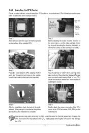
... layer of thermal grease on the push pins diagonally. Step 6: Finally, attach the power connector of the CPU cooler to install.) Step 3: Place the cooler atop the CPU, aligning the four push pins through the pin holes on the motherboard. Hardware Installation Direction of the Arrow...the motherboard. Step 4: You should hear a "click" when pushing down on the surface of the installed CPU. 1-3-2 Installing the CPU Cooler Follow the steps below to correctly install the CPU cooler on the motherboard. (The following procedure uses Intel® boxed cooler as the picture above shows, ...
... layer of thermal grease on the push pins diagonally. Step 6: Finally, attach the power connector of the CPU cooler to install.) Step 3: Place the cooler atop the CPU, aligning the four push pins through the pin holes on the motherboard. Hardware Installation Direction of the Arrow...the motherboard. Step 4: You should hear a "click" when pushing down on the surface of the installed CPU. 1-3-2 Installing the CPU Cooler Follow the steps below to correctly install the CPU cooler on the motherboard. (The following procedure uses Intel® boxed cooler as the picture above shows, ...
Manual
Page 16
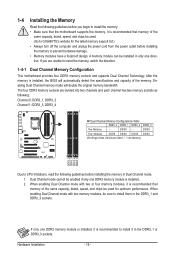
...chips be sure to install them in the DDR3_1 and DDR3_3 sockets. When enabling Dual Channel mode with two memory modules, be used . (Go to GIGABYTE's website for optimum performance. DS/SS Four Modules DS/SS DS/SS DS/SS DS/SS (SS=Single-Sided, DS=Double-Sided, "- -"=No ...Memory) DDR3_2 DDR3_1 DDR3_4 DDR3_3 Due to CPU limitations, read the following guidelines before installing the memory to prevent hardware damage. • Memory modules have a foolproof design. 1-4 Installing the Memory Read ...
...chips be sure to install them in the DDR3_1 and DDR3_3 sockets. When enabling Dual Channel mode with two memory modules, be used . (Go to GIGABYTE's website for optimum performance. DS/SS Four Modules DS/SS DS/SS DS/SS DS/SS (SS=Single-Sided, DS=Double-Sided, "- -"=No ...Memory) DDR3_2 DDR3_1 DDR3_4 DDR3_3 Due to CPU limitations, read the following guidelines before installing the memory to prevent hardware damage. • Memory modules have a foolproof design. 1-4 Installing the Memory Read ...
Manual
Page 22
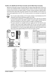
Connect the power supply cable to the CPU. When using a power supply providing a 2x2 12V and a 2x10 power connector. 8 4 5 1 ATX_12V_2X4 ATX_12V_2X4: Pin No. 1/2) ATX_12V_2X4/ATX (2x4 12V Power Connector and 2x12 Main Power ... No. 3.3V 13 3.3V 14 GND 15 +5V 16 GND 17 +5V 18 GND 19 Power Good 20 5VSB (stand by the CPU manufacturer when using an Intel Extreme Edition CPU (130W). • To meet expansion requirements, it is recommended that a power supply that does not provide the required power, the result...
Connect the power supply cable to the CPU. When using a power supply providing a 2x2 12V and a 2x10 power connector. 8 4 5 1 ATX_12V_2X4 ATX_12V_2X4: Pin No. 1/2) ATX_12V_2X4/ATX (2x4 12V Power Connector and 2x12 Main Power ... No. 3.3V 13 3.3V 14 GND 15 +5V 16 GND 17 +5V 18 GND 19 Power Good 20 5VSB (stand by the CPU manufacturer when using an Intel Extreme Edition CPU (130W). • To meet expansion requirements, it is recommended that a power supply that does not provide the required power, the result...
Manual
Page 23
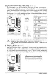
...1 GND 1 SYS_FAN2 2 +12V / Speed Control 3 Sense 4 Reserve 1 SYS_FAN1 1 PWR_FAN SYS_FAN1/PWR_FAN: Pin No. The motherboard supports CPU fan speed control, which requires the use of different color. The types of the connector and the floppy disk drive cable. For purchasing the ...Pin No. Before connecting a floppy disk drive, be installed inside the chassis. 3/4/5) CPU_FAN/SYS_FAN1/SYS_FAN2/PWR_FAN (Fan Headers) The motherboard has a 4-pin CPU fan header (CPU_FAN), a 4-pin (SYS_FAN2) and two 3-pin (SYS_ FAN1) system fan headers, and a 3-pin power fan header (PWR_FAN). Do...
...1 GND 1 SYS_FAN2 2 +12V / Speed Control 3 Sense 4 Reserve 1 SYS_FAN1 1 PWR_FAN SYS_FAN1/PWR_FAN: Pin No. The motherboard supports CPU fan speed control, which requires the use of different color. The types of the connector and the floppy disk drive cable. For purchasing the ...Pin No. Before connecting a floppy disk drive, be installed inside the chassis. 3/4/5) CPU_FAN/SYS_FAN1/SYS_FAN2/PWR_FAN (Fan Headers) The motherboard has a 4-pin CPU fan header (CPU_FAN), a 4-pin (SYS_FAN2) and two 3-pin (SYS_ FAN1) system fan headers, and a 3-pin power fan header (PWR_FAN). Do...
Manual
Page 31
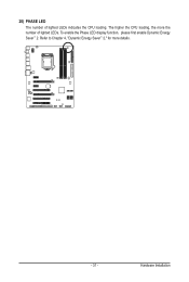
To enable the Phase LED display function, please first enable Dynamic Energy Saver™ 2. The higher the CPU loading, the more details. - 31 - Refer to Chapter 4, "Dynamic Energy Saver™ 2," for more the number of lighted LEDs indicates the CPU loading. Hardware Installation 20) PHASE LED The number of lighted LEDs.
To enable the Phase LED display function, please first enable Dynamic Energy Saver™ 2. The higher the CPU loading, the more details. - 31 - Refer to Chapter 4, "Dynamic Energy Saver™ 2," for more the number of lighted LEDs indicates the CPU loading. Hardware Installation 20) PHASE LED The number of lighted LEDs.
Manual
Page 35
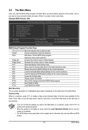
... Optimized Defaults Set Supervisor Password Set User Password Save & Exit Setup Exit Without Saving ESC: Quit F8: Q-Flash Select Item F10: Save & Exit Setup Change CPU's Clock & Voltage F11: Save CMOS to BIOS F12: Load CMOS from BIOS Main Menu Help The on-screen description of a highlighted setup option is displayed...
... Optimized Defaults Set Supervisor Password Set User Password Save & Exit Setup Exit Without Saving ESC: Quit F8: Q-Flash Select Item F10: Save & Exit Setup Change CPU's Clock & Voltage F11: Save CMOS to BIOS F12: Load CMOS from BIOS Main Menu Help The on-screen description of a highlighted setup option is displayed...
Manual
Page 36
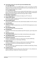
...that stop the system boot, etc. Advanced BIOS Features Use this menu to configure the device boot order, advanced features available on the CPU, and the primary display adapter. Integrated Peripherals Use this menu to configure all peripheral devices, such as IDE, SATA, USB, integrated audio...It allows you to save the current BIOS settings to a profile. You can also carry out this menu to see information about autodetected system/CPU temperature, system voltage and fan speed, etc. Load Fail-Safe Defaults Fail-Safe defaults are factory settings for the most stable, ...
...that stop the system boot, etc. Advanced BIOS Features Use this menu to configure the device boot order, advanced features available on the CPU, and the primary display adapter. Integrated Peripherals Use this menu to configure all peripheral devices, such as IDE, SATA, USB, integrated audio...It allows you to save the current BIOS settings to a profile. You can also carry out this menu to see information about autodetected system/CPU temperature, system voltage and fan speed, etc. Load Fail-Safe Defaults Fail-Safe defaults are factory settings for the most stable, ...
Manual
Page 37
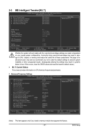
... Advanced Frequency Settings CMOS Setup Utility-Copyright (C) 1984-2009 Award Software Advanced Frequency Settings CPU Clock Ratio CPU Frequency } Advanced CPU Core Features QPI Clock Ratio QPI Link Speed Uncore Clock Ratio Uncore Frequency >>>>> Standard ... Profile (X.M.P.) (Note) System Memory Multiplier (SPD) Memory Frequency (Mhz) 1333 PCI Express Frequency (Mhz) >>>>> Advanced Clock Control CPU Clock Drive PCI Express Clock Drive CPU Clock Skew [22X] 2.93GHz (133x22) [Press Enter] [Auto] 4.8GHz 18x 2400MHz [Disabled] 133 [Disabled] [Auto] ...
... Advanced Frequency Settings CMOS Setup Utility-Copyright (C) 1984-2009 Award Software Advanced Frequency Settings CPU Clock Ratio CPU Frequency } Advanced CPU Core Features QPI Clock Ratio QPI Link Speed Uncore Clock Ratio Uncore Frequency >>>>> Standard ... Profile (X.M.P.) (Note) System Memory Multiplier (SPD) Memory Frequency (Mhz) 1333 PCI Express Frequency (Mhz) >>>>> Advanced Clock Control CPU Clock Drive PCI Express Clock Drive CPU Clock Skew [22X] 2.93GHz (133x22) [Press Enter] [Auto] 4.8GHz 18x 2400MHz [Disabled] 133 [Disabled] [Auto] ...
Manual
Page 38
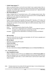
.... BIOS Setup - 38 - This feature only works for the installed CPU. All Enables all CPU cores. CPU Cores Enabled (Note) CPU Multi-Threading (Note) CPU Enhanced Halt (C1E) (Note) C3/C6/C7 State Support (Note) CPU Thermal Monitor (Note) CPU EIST Function (Note) Bi-Directional PROCHOT (Note) [Auto] [All]...F6: Fail-Safe Defaults ESC: Exit F1: General Help F7: Optimized Defaults Intel(R) Turbo Boost Tech. When enabled, the CPU core frequency and voltage will be reduced during system halt state to alter the clock ratio for operating systems that supports this ...
.... BIOS Setup - 38 - This feature only works for the installed CPU. All Enables all CPU cores. CPU Cores Enabled (Note) CPU Multi-Threading (Note) CPU Enhanced Halt (C1E) (Note) C3/C6/C7 State Support (Note) CPU Thermal Monitor (Note) CPU EIST Function (Note) Bi-Directional PROCHOT (Note) [Auto] [All]...F6: Fail-Safe Defaults ESC: Exit F1: General Help F7: Optimized Defaults Intel(R) Turbo Boost Tech. When enabled, the CPU core frequency and voltage will be reduced during system halt state to alter the clock ratio for operating systems that supports this ...
Manual
Page 39
...decrease power consumption. For more enhanced power-saving state than C1. Auto lets the BIOS automatically configure this setting. (Default: Auto) CPU EIST Function (Note) Enables or disables Enhanced Intel SpeedStep Technology (EIST). Note: If your system fails to boot after overclocking, ...ting. (Default: Auto) Bi-Directional PROCHOT (Note) Auto Enabled Disabled Lets BIOS automatically configure this setting. (Default) When the CPU or chipset detects that supports this set the QPI clock ratio. QPI Clock Ratio Allows you to decrease heat production. Uncore Clock ...
...decrease power consumption. For more enhanced power-saving state than C1. Auto lets the BIOS automatically configure this setting. (Default: Auto) CPU EIST Function (Note) Enables or disables Enhanced Intel SpeedStep Technology (EIST). Note: If your system fails to boot after overclocking, ...ting. (Default: Auto) Bi-Directional PROCHOT (Note) Auto Enabled Disabled Lets BIOS automatically configure this setting. (Default) When the CPU or chipset detects that supports this set the QPI clock ratio. QPI Clock Ratio Allows you to decrease heat production. Uncore Clock ...
Manual
Page 40
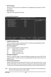
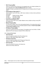
...multiplier according to enhance memory performance when enabled. Options are : 700mV, 800mV, 900mV (default), 1000mV. CPU Clock Skew Allows you to set in accordance with the CPU specifications. Disabled Disables this feature. Auto sets the PCIe clock frequency to standard 100 MHz. (Default: ...memory frequency that supports this function. (Default) Profile1 Uses Profile 1 settings. System Memory Multiplier (SPD) Allows you to set the CPU base clock. the second is the normal operating frequency of the PCI Express and Chipset clock. Options are: 0ps~750ps. (Default: ...
...multiplier according to enhance memory performance when enabled. Options are : 700mV, 800mV, 900mV (default), 1000mV. CPU Clock Skew Allows you to set in accordance with the CPU specifications. Disabled Disables this feature. Auto sets the PCIe clock frequency to standard 100 MHz. (Default: ...memory frequency that supports this function. (Default) Profile1 Uses Profile 1 settings. System Memory Multiplier (SPD) Allows you to set the CPU base clock. the second is the normal operating frequency of the PCI Express and Chipset clock. Options are: 0ps~750ps. (Default: ...
Manual
Page 42
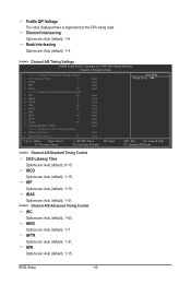
... (default), 1~31. tWTR Options are : Auto (default), 1~63. tRCD Options are: Auto (default), 1~15. Profile QPI Voltage The value displayed here is dependent on the CPU being used.
... (default), 1~31. tWTR Options are : Auto (default), 1~63. tRCD Options are: Auto (default), 1~15. Profile QPI Voltage The value displayed here is dependent on the CPU being used.


