
Manual
Page 1
... that before you can quickly configure a RAIDready system for the Intel SATA controllers. Or you have to expand its capacity. Using GIGABYTE eXtreme Hard Drive (X.H.D) Instructions:(Note 2) Before launching X.H.D, make sure the newly added harddrive has equal or greater capacity than or equal... Chapter 5, "Installing the SATA RAID/AHCI Driver and Operating System." ) Step 3: Install the motherboard drivers and the X.H.D utiltiy After installing the operating system, insert the motherboard driver disk. Setting Up a RAID-Ready System Step 1: Configure the system BIOS Enter the system...
... that before you can quickly configure a RAIDready system for the Intel SATA controllers. Or you have to expand its capacity. Using GIGABYTE eXtreme Hard Drive (X.H.D) Instructions:(Note 2) Before launching X.H.D, make sure the newly added harddrive has equal or greater capacity than or equal... Chapter 5, "Installing the SATA RAID/AHCI Driver and Operating System." ) Step 3: Install the motherboard drivers and the X.H.D utiltiy After installing the operating system, insert the motherboard driver disk. Setting Up a RAID-Ready System Step 1: Configure the system BIOS Enter the system...
Manual
Page 1
GA-P55-UD3L-TPM/ GA-P55-UD3L/ GA-P55-US3L LGA1156 socket motherboard for Intel® Core™ i7 processor family/ Intel® Core™ i5 processor family User's Manual Rev. 1002 12ME-P55UD3L-1002R
GA-P55-UD3L-TPM/ GA-P55-UD3L/ GA-P55-US3L LGA1156 socket motherboard for Intel® Core™ i7 processor family/ Intel® Core™ i5 processor family User's Manual Rev. 1002 12ME-P55UD3L-1002R

Manual
Page 3
Motherboard GA-P55-UD3L-TPM Oct. 5, 2009 Motherboard GA-P55-UD3L-TPM Oct. 5, 2009
Motherboard GA-P55-UD3L-TPM Oct. 5, 2009 Motherboard GA-P55-UD3L-TPM Oct. 5, 2009
Manual
Page 4
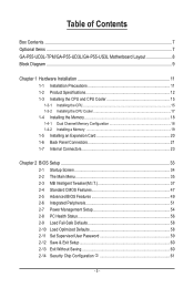
... the product. For product-related information, check on our website at: http://www.gigabyte.com.tw Identifying Your Motherboard Revision The revision number on how to use of this product, GIGABYTE provides the following types of documentations: For quick set-up of this manual may... transmitted, or published in this manual is protected by copyright laws and is the property of the motherboard is 1.0. For example, "REV: 1.0" means the revision of GIGABYTE. All rights reserved. For detailed product information, carefully read or download the information on/from the Support...
... the product. For product-related information, check on our website at: http://www.gigabyte.com.tw Identifying Your Motherboard Revision The revision number on how to use of this product, GIGABYTE provides the following types of documentations: For quick set-up of this manual may... transmitted, or published in this manual is protected by copyright laws and is the property of the motherboard is 1.0. For example, "REV: 1.0" means the revision of GIGABYTE. All rights reserved. For detailed product information, carefully read or download the information on/from the Support...
Manual
Page 5
Table of Contents Box Contents...7 Optional Items...7 GA-P55-UD3L-TPM/GA-P55-UD3L/GA-P55-US3L Motherboard Layout 8 Block Diagram...9 Chapter 1 Hardware Installation 11 1-1 Installation Precautions 11 1-2 Product Specifications 12 1-3 Installing the CPU and CPU Cooler 15 1-3-1 Installing the CPU 15 1-3-2 Installing ...
Table of Contents Box Contents...7 Optional Items...7 GA-P55-UD3L-TPM/GA-P55-UD3L/GA-P55-US3L Motherboard Layout 8 Block Diagram...9 Chapter 1 Hardware Installation 11 1-1 Installation Precautions 11 1-2 Product Specifications 12 1-3 Installing the CPU and CPU Cooler 15 1-3-1 Installing the CPU 15 1-3-2 Installing ...
Manual
Page 7
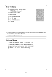
... USB 2.0 bracket (Part No. 12CR1-1UB030-5*R) 2-port SATA power cable (Part No. 12CF1-2SERPW-0*R) S/PDIF In cable (Part No. 12CR1-1SPDIN-0*R) - 7 - Box Contents GA-P55-UD3L-TPM, GA-P55-UD3L, or GA-P55-US3L motherboard Motherboard driver disk User's Manual Quick Installation Guide One IDE cable Two SATA 3Gb/s cables I/O Shield • The box contents above are subject to...
... USB 2.0 bracket (Part No. 12CR1-1UB030-5*R) 2-port SATA power cable (Part No. 12CF1-2SERPW-0*R) S/PDIF In cable (Part No. 12CR1-1SPDIN-0*R) - 7 - Box Contents GA-P55-UD3L-TPM, GA-P55-UD3L, or GA-P55-US3L motherboard Motherboard driver disk User's Manual Quick Installation Guide One IDE cable Two SATA 3Gb/s cables I/O Shield • The box contents above are subject to...
Manual
Page 8
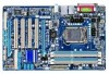
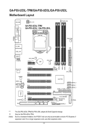
...x1 expansion card. For a longer expansion card, use other expansion slots. - 8 - GA-P55-UD3L-TPM/GA-P55-UD3L/GA-P55-US3L Motherboard Layout KB_USB ATX_12V GA-P55-UD3L-TPM/ GA-P55-UD3L / GA-P55-US3L PHASE LED LGA1156 PWR_FAN COAXIAL COMA LPT R_USB ATX USB_LAN AUDIO F_AUDIO SYS_FAN1 PCIEX1 (Note) BAT...PCI2 PCI3 PCI4 SYS_FAN2 Intel® P55 SATA2_0 SATA2_1 SATA2_2 SATA2_5 SATA2_4SATA2_3 IDE IT8720 B_BIOS M_BIOS FDD PCIEX4 F_USB3 F_USB2 F_USB1 GSATA2_0 CLR_CMOS GIGABYTE SATA2 GSATA2_1 F_PANEL "*" j (Note) The GA-P55-UD3L-TPM/GA-P55-UD3L adopts All-Solid Capacitor design....
...x1 expansion card. For a longer expansion card, use other expansion slots. - 8 - GA-P55-UD3L-TPM/GA-P55-UD3L/GA-P55-US3L Motherboard Layout KB_USB ATX_12V GA-P55-UD3L-TPM/ GA-P55-UD3L / GA-P55-US3L PHASE LED LGA1156 PWR_FAN COAXIAL COMA LPT R_USB ATX USB_LAN AUDIO F_AUDIO SYS_FAN1 PCIEX1 (Note) BAT...PCI2 PCI3 PCI4 SYS_FAN2 Intel® P55 SATA2_0 SATA2_1 SATA2_2 SATA2_5 SATA2_4SATA2_3 IDE IT8720 B_BIOS M_BIOS FDD PCIEX4 F_USB3 F_USB2 F_USB1 GSATA2_0 CLR_CMOS GIGABYTE SATA2 GSATA2_1 F_PANEL "*" j (Note) The GA-P55-UD3L-TPM/GA-P55-UD3L adopts All-Solid Capacitor design....
Manual
Page 11
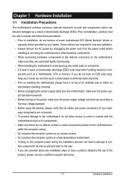
...8226; Always remove the AC power by your hands dry and first touch a metal object to eliminate static electricity. • Prior to installing the motherboard, please have a problem related to wear an electrostatic discharge (ESD) wrist strap when handling electronic com- ponents such as a result of electrostatic ...have it on top of an antistatic pad or within an electrostatic shielding container. • Before unplugging the power supply cable from the motherboard, make sure the power supply has been turned off. • Before turning on the power, make sure the power supply voltage ...
...8226; Always remove the AC power by your hands dry and first touch a metal object to eliminate static electricity. • Prior to installing the motherboard, please have a problem related to wear an electrostatic discharge (ESD) wrist strap when handling electronic com- ponents such as a result of electrostatic ...have it on top of an antistatic pad or within an electrostatic shielding container. • Before unplugging the power supply cable from the motherboard, make sure the power supply has been turned off. • Before turning on the power, make sure the power supply voltage ...
Manual
Page 14
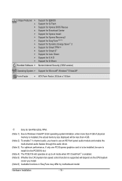
... Internet Security (OEM version) Operating System w Support for Microsoft® Windows® 7/Vista/XP Form Factor w ATX Form Factor; 30.5cm x 19.0cm j Only for GA-P55-UD3L-TPM. (Note 1) Due to Windows Vista/XP 32-bit operating system limitation, when more than 4 GB of physical memory is installed, the actual memory... CPU/system fan speed control function is supported will depend on the CPU/system cooler you install. (Note 6) Available functions in EasyTune may differ by motherboard model.
... Internet Security (OEM version) Operating System w Support for Microsoft® Windows® 7/Vista/XP Form Factor w ATX Form Factor; 30.5cm x 19.0cm j Only for GA-P55-UD3L-TPM. (Note 1) Due to Windows Vista/XP 32-bit operating system limitation, when more than 4 GB of physical memory is installed, the actual memory... CPU/system fan speed control function is supported will depend on the CPU/system cooler you install. (Note 6) Available functions in EasyTune may differ by motherboard model.
Manual
Page 15
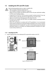
... CPU Notch Notch Triangle Pin One Marking on the CPU - 15 - It is not installed, otherwise overheating and dam- Locate the alignment keys on the motherboard CPU socket and the notches on the surface of the CPU may locate the notches on both sides of the CPU and alignment keys on... meet the standard requirements for the latest CPU support list.) • Always turn on the computer if the CPU cooler is not recommended that the motherboard supports the CPU. (Go to GIGABYTE's website for the peripherals.
... CPU Notch Notch Triangle Pin One Marking on the CPU - 15 - It is not installed, otherwise overheating and dam- Locate the alignment keys on the motherboard CPU socket and the notches on the surface of the CPU may locate the notches on both sides of the CPU and alignment keys on... meet the standard requirements for the latest CPU support list.) • Always turn on the computer if the CPU cooler is not recommended that the motherboard supports the CPU. (Go to GIGABYTE's website for the peripherals.
Manual
Page 16
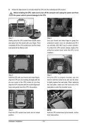
.... Step 1: Gently press the CPU socket lever handle down and away from the power outlet to prevent damage to correctly install the CPU into the motherboard CPU socket. Align the CPU pin one marking (triangle) with the socket alignment keys) and gently insert the CPU into its locked position. Hardware Installation...
.... Step 1: Gently press the CPU socket lever handle down and away from the power outlet to prevent damage to correctly install the CPU into the motherboard CPU socket. Align the CPU pin one marking (triangle) with the socket alignment keys) and gently insert the CPU into its locked position. Hardware Installation...
Manual
Page 17
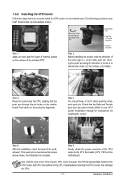
... installation is to install.) Step 3: Place the cooler atop the CPU, aligning the four push pins through the pin holes on the motherboard. 1-3-2 Installing the CPU Cooler Follow the steps below to your CPU cooler installation manual for instructions on installing the cooler.) Step 5: ...After the installation, check the back of the motherboard. Step 6: Finally, attach the power connector of arrow is to remove the cooler, on the contrary, is complete. Hardware Installation Inadequately...
... installation is to install.) Step 3: Place the cooler atop the CPU, aligning the four push pins through the pin holes on the motherboard. 1-3-2 Installing the CPU Cooler Follow the steps below to your CPU cooler installation manual for instructions on installing the cooler.) Step 5: ...After the installation, check the back of the motherboard. Step 6: Finally, attach the power connector of arrow is to remove the cooler, on the contrary, is complete. Hardware Installation Inadequately...
Manual
Page 18
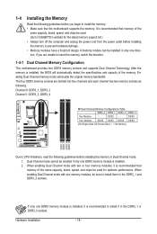
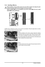
...DDR3_1 and DDR3_3 sockets. Hardware Installation - 18 - A memory module can be sure to insert the memory, switch the direction. 1-4-1 Dual Channel Memory Configuration This motherboard provides four DDR3 memory sockets and supports Dual Channel Technology. If you begin to install the memory: • Make sure that memory of the same... the power outlet before installing the memory in the DDR3_1 or DDR3_3 sockets. After the memory is installed. 2. It is recommended that the motherboard supports the memory. If only one DDR3 memory module is installed, it is recommended to...
...DDR3_1 and DDR3_3 sockets. Hardware Installation - 18 - A memory module can be sure to insert the memory, switch the direction. 1-4-1 Dual Channel Memory Configuration This motherboard provides four DDR3 memory sockets and supports Dual Channel Technology. If you begin to install the memory: • Make sure that memory of the same... the power outlet before installing the memory in the DDR3_1 or DDR3_3 sockets. After the memory is installed. 2. It is recommended that the motherboard supports the memory. If only one DDR3 memory module is installed, it is recommended to...
Manual
Page 19
... DIMMs are not compatible to each other or DDR DIMMs. Be sure to install DDR3 DIMMs on the socket. Place the memory module on this motherboard.
... DIMMs are not compatible to each other or DDR DIMMs. Be sure to install DDR3 DIMMs on the socket. Place the memory module on this motherboard.
Manual
Page 20
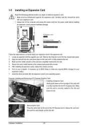
... and then pull the card straight up from the slot. If necessary, go to BIOS Setup to install an expansion card: • Make sure the motherboard supports the expansion card. Make sure the card is fully inserted into the slot. 4. Remove the metal slot cover from the power outlet before you...
... and then pull the card straight up from the slot. If necessary, go to BIOS Setup to install an expansion card: • Make sure the motherboard supports the expansion card. Make sure the card is fully inserted into the slot. 4. Remove the metal slot cover from the power outlet before you...
Manual
Page 21
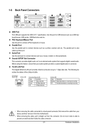
... port provides Internet connection at up to connect devices such as a printer, scanner and etc. Hardware Installation Do not rock it straight out from the motherboard. • When removing the cable, pull it side to side to connect a PS/2 keyboard or mouse. 1-6 Back Panel Connectors USB Port The USB port supports...
... port provides Internet connection at up to connect devices such as a printer, scanner and etc. Hardware Installation Do not rock it straight out from the motherboard. • When removing the cable, pull it side to side to connect a PS/2 keyboard or mouse. 1-6 Back Panel Connectors USB Port The USB port supports...
Manual
Page 23
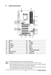
...) F_PANEL 12) F_AUDIO 13) CD_IN 14) SPDIF_I 15) SPDIF_O 16) F_USB1/F_USB2/F_USB3 17) CLR_CMOS 18) PHASE_LED Read the following guidelines before turning on the motherboard. - 23 - Hardware Installation Unplug the power cord from the power outlet to prevent damage to the devices. • After installing the device and before connecting...
...) F_PANEL 12) F_AUDIO 13) CD_IN 14) SPDIF_I 15) SPDIF_O 16) F_USB1/F_USB2/F_USB3 17) CLR_CMOS 18) PHASE_LED Read the following guidelines before turning on the motherboard. - 23 - Hardware Installation Unplug the power cord from the power outlet to prevent damage to the devices. • After installing the device and before connecting...
Manual
Page 24
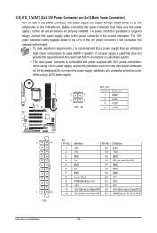
...is not connected, the computer will not start. • To meet expansion requirements, it is turned off and all the components on the motherboard. 1/2) ATX_12V/ATX (2x2 12V Power Connector and 2x12 Main Power Connector) With the use of the power connector, the power supply can supply... cable into pins under the protective cover when using a 2x12 power supply, remove the protective cover from the main power connector on the motherboard. Before connecting the power connector, first make sure the power supply is recommended that a power supply that does not provide the required power...
...is not connected, the computer will not start. • To meet expansion requirements, it is turned off and all the components on the motherboard. 1/2) ATX_12V/ATX (2x2 12V Power Connector and 2x12 Main Power Connector) With the use of the power connector, the power supply can supply... cable into pins under the protective cover when using a 2x12 power supply, remove the protective cover from the main power connector on the motherboard. Before connecting the power connector, first make sure the power supply is recommended that a power supply that does not provide the required power...
Manual
Page 25
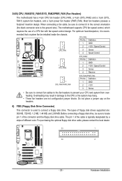
...; Be sure to connect fan cables to the fan headers to connect a floppy disk drive. Most fan headers possess a foolproof insertion design. The motherboard supports CPU fan speed control, which requires the use of different color. Definition 1 SYS_FAN2 1 GND 2 +12V / Speed Control 3 Sense 4 ...Reserve 1 SYS_FAN1/PWR_FAN SYS_FAN1/PWR_FAN: Pin No. 3/4/5) CPU_FAN/SYS_FAN1/SYS_FAN2/PWR_FAN (Fan Headers) The motherboard has a 4-pin CPU fan header (CPU_FAN), a 4-pin (SYS_FAN2) and a 3-pin (SYS_ FAN1) system fan headers, and a 3-pin power fan header (PWR_FAN...
...; Be sure to connect fan cables to the fan headers to connect a floppy disk drive. Most fan headers possess a foolproof insertion design. The motherboard supports CPU fan speed control, which requires the use of different color. Definition 1 SYS_FAN2 1 GND 2 +12V / Speed Control 3 Sense 4 ...Reserve 1 SYS_FAN1/PWR_FAN SYS_FAN1/PWR_FAN: Pin No. 3/4/5) CPU_FAN/SYS_FAN1/SYS_FAN2/PWR_FAN (Fan Headers) The motherboard has a 4-pin CPU fan header (CPU_FAN), a 4-pin (SYS_FAN2) and a 3-pin (SYS_ FAN1) system fan headers, and a 3-pin power fan header (PWR_FAN...
Manual
Page 29
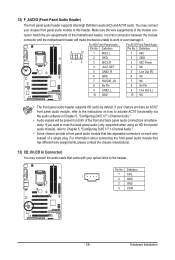
...Out (L) 10 GND 10 NC • The front panel audio header supports HD audio by default. Incorrect connection between the module connector and the motherboard header will be present on how to activate AC'97 functionality via the audio software in Chapter 5, "Configuring 2/4/5.1/7.1-Channel Audio." • Audio signals... device unable to this header. If your chassis provides an AC'97 front panel audio module, refer to the instructions on both of the motherboard header. Pin No. For HD Front Panel Audio: For AC'97 Front Panel Audio: Pin No. 12) F_AUDIO (Front Panel Audio Header...
...Out (L) 10 GND 10 NC • The front panel audio header supports HD audio by default. Incorrect connection between the module connector and the motherboard header will be present on how to activate AC'97 functionality via the audio software in Chapter 5, "Configuring 2/4/5.1/7.1-Channel Audio." • Audio signals... device unable to this header. If your chassis provides an AC'97 front panel audio module, refer to the instructions on both of the motherboard header. Pin No. For HD Front Panel Audio: For AC'97 Front Panel Audio: Pin No. 12) F_AUDIO (Front Panel Audio Header...


