
Manual
Page 3
... their respective owners. Disclaimer Information in this : "REV: X.X." For product-related information, check on our website at: http://www.gigabyte.com.tw Identifying Your Motherboard Revision The revision number on our website. Example: Check your motherboard looks like this manual are legally registered...form or by any means without prior notice. No part of the motherboard is the property of the product, read the Quick Installation Guide included with the product. For detailed product information, carefully read the User's Manual. For instructions on...
... their respective owners. Disclaimer Information in this : "REV: X.X." For product-related information, check on our website at: http://www.gigabyte.com.tw Identifying Your Motherboard Revision The revision number on our website. Example: Check your motherboard looks like this manual are legally registered...form or by any means without prior notice. No part of the motherboard is the property of the product, read the Quick Installation Guide included with the product. For detailed product information, carefully read the User's Manual. For instructions on...
Manual
Page 4
Table of Contents Box Contents ...6 Optional Items...6 GA-P43-ES3G Motherboard Layout 7 Block Diagram...8 Chapter 1 Hardware Installation 9 1-1 Installation Precautions 9 1-2 Product Specifications 10 1-3 Installing the CPU and CPU Cooler 13 1-3-1 Installing the CPU 13 1-3-2 Installing the CPU Cooler 15 1-4 Installing the Memory 16 1-4-1 Dual Channel Memory Configuration 16 1-4-2 Installing a Memory 17 1-5 Installing an Expansion Card 18 1-6 Back Panel Connectors 19 1-7 Internal Connectors 21...
Table of Contents Box Contents ...6 Optional Items...6 GA-P43-ES3G Motherboard Layout 7 Block Diagram...8 Chapter 1 Hardware Installation 9 1-1 Installation Precautions 9 1-2 Product Specifications 10 1-3 Installing the CPU and CPU Cooler 13 1-3-1 Installing the CPU 13 1-3-2 Installing the CPU Cooler 15 1-4 Installing the Memory 16 1-4-1 Dual Channel Memory Configuration 16 1-4-2 Installing a Memory 17 1-5 Installing an Expansion Card 18 1-6 Back Panel Connectors 19 1-7 Internal Connectors 21...

Manual
Page 5
Chapter 3 Drivers Installation 57 3-1 Installing Chipset Drivers 57 3-2 Application Software 58 3-3 Technical Manuals 58 3-4 Contact ...59 3-5 System ...59 3-6 Download Center 60 Chapter 4 Unique Features 61 4-1 Xpress Recovery2 61 4-2 BIOS Update ...
Chapter 3 Drivers Installation 57 3-1 Installing Chipset Drivers 57 3-2 Application Software 58 3-3 Technical Manuals 58 3-4 Contact ...59 3-5 System ...59 3-6 Download Center 60 Chapter 4 Unique Features 61 4-1 Xpress Recovery2 61 4-2 BIOS Update ...
Manual
Page 6
Optional Items Floppy disk drive cable (Part No. 12CF1-1FD001-7*R) 2-port USB 2.0 bracket (Part No. 12CR1-1UB030-5*R) 2-port SATA power cable (Part No. 12CF1-2SERPW-0*R) - 6 - Box Contents GA-P43-ES3G motherboard Motherboard driver disk User's Manual Quick Installation Guide One IDE cable Two SATA 3Gb/s cables I/O Shield • The box contents above are subject to change without notice. • The motherboard image is for reference only and the actual items shall depend on product package you obtain. The box contents are for reference only.
Optional Items Floppy disk drive cable (Part No. 12CF1-1FD001-7*R) 2-port USB 2.0 bracket (Part No. 12CR1-1UB030-5*R) 2-port SATA power cable (Part No. 12CF1-2SERPW-0*R) - 6 - Box Contents GA-P43-ES3G motherboard Motherboard driver disk User's Manual Quick Installation Guide One IDE cable Two SATA 3Gb/s cables I/O Shield • The box contents above are subject to change without notice. • The motherboard image is for reference only and the actual items shall depend on product package you obtain. The box contents are for reference only.

Manual
Page 9
...do not have an ESD wrist strap, keep your hands dry and first touch a metal object to eliminate static electricity. • Prior to installing the motherboard, please have a problem related to the use of the product, please consult a certified computer technician. - 9 - These stickers are...an antistatic pad or within an electrostatic shielding container. • Before unplugging the power supply cable from the power outlet before installing or removing the motherboard or other hardware components. • When connecting hardware components to the internal connectors on the motherboard, ...
...do not have an ESD wrist strap, keep your hands dry and first touch a metal object to eliminate static electricity. • Prior to installing the motherboard, please have a problem related to the use of the product, please consult a certified computer technician. - 9 - These stickers are...an antistatic pad or within an electrostatic shielding container. • Before unplugging the power supply cable from the power outlet before installing or removing the motherboard or other hardware components. • When connecting hardware components to the internal connectors on the motherboard, ...

Manual
Page 11
... Š CPU/System fan speed detection Š CPU overheating warning Š CPU/System fan fail warning Š CPU/System smart fan control (Note 3) - 11 - Hardware Installation
... Š CPU/System fan speed detection Š CPU overheating warning Š CPU/System fan fail warning Š CPU/System smart fan control (Note 3) - 11 - Hardware Installation
Manual
Page 12
...for @BIOS Š Support for Download Center Š Support for Q-Flash Š Support for EasyTune (Note 4) Š Support for Xpress Install Š Support for Xpress Recovery2 Š Support for Virtual Dual BIOS Š Support for Easy Energy Saver (Note 5) Š Norton ...install. (Note 4) Available functions in EasyTune may differ by motherboard model. (Note 5) Due to the hardware limitation, you must install the Intel ® CoreTM 2 Extreme/ CoreTM 2 Quad/ CoreTM 2 Duo/ Pentium Dual-Core/ Celeron Dual-Core/ Celeron 400 Series CPU to enable support for Easy Energy Saver. GA-P43-ES3G...
...for @BIOS Š Support for Download Center Š Support for Q-Flash Š Support for EasyTune (Note 4) Š Support for Xpress Install Š Support for Xpress Recovery2 Š Support for Virtual Dual BIOS Š Support for Easy Energy Saver (Note 5) Š Norton ...install. (Note 4) Available functions in EasyTune may differ by motherboard model. (Note 5) Due to the hardware limitation, you must install the Intel ® CoreTM 2 Extreme/ CoreTM 2 Quad/ CoreTM 2 Duo/ Pentium Dual-Core/ Celeron Dual-Core/ Celeron 400 Series CPU to enable support for Easy Energy Saver. GA-P43-ES3G...

Manual
Page 13
... Corner of the CPU Socket Notch Notch Triangle Pin One Marking on the computer if the CPU cooler is not recom- Hardware Installation The CPU cannot be set the frequency beyond hardware specifications since it does not meet the standard requirements for the latest CPU support... do so according to your hardware specifications including the CPU, graphics card, memory, hard drive, etc. 1-3-1 Installing the CPU A. mended that the motherboard supports the CPU. (Go to GIGABYTE's website for the peripherals. If you may occur. • Set the CPU host frequency in accordance with the...
... Corner of the CPU Socket Notch Notch Triangle Pin One Marking on the computer if the CPU cooler is not recom- Hardware Installation The CPU cannot be set the frequency beyond hardware specifications since it does not meet the standard requirements for the latest CPU support... do so according to your hardware specifications including the CPU, graphics card, memory, hard drive, etc. 1-3-1 Installing the CPU A. mended that the motherboard supports the CPU. (Go to GIGABYTE's website for the peripherals. If you may occur. • Set the CPU host frequency in accordance with the...
Manual
Page 14
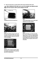
... power outlet to prevent damage to correctly install the CPU into position. Align the CPU pin one marking (triangle) with the pin one corner of the CPU socket (or you may align the CPU notches with your thumb and index fingers. GA-P43-ES3G Motherboard - 14 - CPU Socket Lever ...Step 1: Completely raise the CPU socket lever. Follow the steps below to the CPU. B. Step 5: Once the CPU is not installed.) Step 4: Hold the CPU with the socket alignment keys) and...
... power outlet to prevent damage to correctly install the CPU into position. Align the CPU pin one marking (triangle) with the pin one corner of the CPU socket (or you may align the CPU notches with your thumb and index fingers. GA-P43-ES3G Motherboard - 14 - CPU Socket Lever ...Step 1: Completely raise the CPU socket lever. Follow the steps below to the CPU. B. Step 5: Once the CPU is not installed.) Step 4: Hold the CPU with the socket alignment keys) and...

Manual
Page 15
... motherboard. Direction of the Arrow Sign on the Male Push Pin Male Push Pin The Top of Female Push Pin Female Push Pin Step 2: Before installing the cooler, note the direction of the arrow sign on the male push pin. (Turning the push pin along the direction of arrow is to... install.) Step 3: Place the cooler atop the CPU, aligning the four push pins through the pin holes on the motherboard. Use extreme care when removing the ...
... motherboard. Direction of the Arrow Sign on the Male Push Pin Male Push Pin The Top of Female Push Pin Female Push Pin Step 2: Before installing the cooler, note the direction of the arrow sign on the male push pin. (Turning the push pin along the direction of arrow is to... install.) Step 3: Place the cooler atop the CPU, aligning the four push pins through the pin holes on the motherboard. Use extreme care when removing the ...
Manual
Page 16
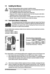
... automatically detect the specifications and capacity of the same capacity, brand, speed, and chips be used . (Go to GIGABYTE's website for optimum performance. DS/SS Four Modules DS/SS DS/SS DS/SS DS/SS (SS=Single-Sided,...installed, a message which says memory is recommended that the motherboard supports the memory. The four DDR2 memory sockets are divided into two channels and each channel has two memory sockets as following: Channel 0: DDR2_1, DDR2_2 Channel 1: DDR2_3, DDR2_4 Dual Channel Memory ConfigurationsTable DDR2_1 DDR2_2 DDR2_3 DDR2_4 Two Modules DS/SS - - GA-P43-ES3G...
... automatically detect the specifications and capacity of the same capacity, brand, speed, and chips be used . (Go to GIGABYTE's website for optimum performance. DS/SS Four Modules DS/SS DS/SS DS/SS DS/SS (SS=Single-Sided,...installed, a message which says memory is recommended that the motherboard supports the memory. The four DDR2 memory sockets are divided into two channels and each channel has two memory sockets as following: Channel 0: DDR2_1, DDR2_2 Channel 1: DDR2_3, DDR2_4 Dual Channel Memory ConfigurationsTable DDR2_1 DDR2_2 DDR2_3 DDR2_4 Two Modules DS/SS - - GA-P43-ES3G...

Manual
Page 17
... sockets. Place the memory module on this motherboard. DDR2 DIMMs are not compatible to DDR DIMMs. Be sure to the memory module. Hardware Installation As indicated in the picture on the left, place your memory modules in one direction. Step 2: The clips at both ends of the memory.... Notch DDR2 DIMM A DDR2 memory module has a notch, so it vertically into place when the memory module is securely inserted. - 17 - 1-4-2 Installing a Memory Before installing a memory module , make sure to turn off the computer and unplug the power cord from the power outlet to prevent damage to...
... sockets. Place the memory module on this motherboard. DDR2 DIMMs are not compatible to DDR DIMMs. Be sure to the memory module. Hardware Installation As indicated in the picture on the left, place your memory modules in one direction. Step 2: The clips at both ends of the memory.... Notch DDR2 DIMM A DDR2 memory module has a notch, so it vertically into place when the memory module is securely inserted. - 17 - 1-4-2 Installing a Memory Before installing a memory module , make sure to turn off the computer and unplug the power cord from the power outlet to prevent damage to...
Manual
Page 18
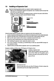
... slot that came with the slot, and press down on the card are completely inserted into the PCI Express x16 slot. After installing all expansion cards, replace the chassis cover(s). 6. Secure the card's metal bracket to the chassis back panel with the expansion card...Installing a Graphics Card: Gently insert the graphics card into the slot. 4. Make sure the graphics card is fully seated in your expansion card in the expansion slot. 1. Turn on your expansion card(s). 7. If necessary, go to BIOS Setup to make any required BIOS changes for your computer. GA-P43-ES3G...
... slot that came with the slot, and press down on the card are completely inserted into the PCI Express x16 slot. After installing all expansion cards, replace the chassis cover(s). 6. Secure the card's metal bracket to the chassis back panel with the expansion card...Installing a Graphics Card: Gently insert the graphics card into the slot. 4. Make sure the graphics card is fully seated in your expansion card in the expansion slot. 1. Turn on your expansion card(s). 7. If necessary, go to BIOS Setup to make any required BIOS changes for your computer. GA-P43-ES3G...

Manual
Page 19
... data rate Activity LED: State Description Blinking Data transmission or receiving is occurring Off No data transmission or receiving is also called a printer port. Hardware Installation Serial Port Use the serial port to 1 Gbps data rate. RJ-45 LAN Port The Gigabit Ethernet LAN port provides Internet connection at up to...
... data rate Activity LED: State Description Blinking Data transmission or receiving is occurring Off No data transmission or receiving is also called a printer port. Hardware Installation Serial Port Use the serial port to 1 Gbps data rate. RJ-45 LAN Port The Gigabit Ethernet LAN port provides Internet connection at up to...

Manual
Page 21
... the power cord from the power outlet to prevent damage to the devices. • After installing the device and before connecting external devices: • First make sure the device cable has been securely attached to turn off the devices and your ...) CLR_CMOS Read the following guidelines before turning on the computer, make sure your devices are compliant with the connectors you wish to connect. • Before installing the devices, be sure to the connector on the motherboard. - 21 -
... the power cord from the power outlet to prevent damage to the devices. • After installing the device and before connecting external devices: • First make sure the device cable has been securely attached to turn off the devices and your ...) CLR_CMOS Read the following guidelines before turning on the computer, make sure your devices are compliant with the connectors you wish to connect. • Before installing the devices, be sure to the connector on the motherboard. - 21 -
Manual
Page 22
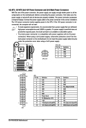
...) 24 Definition 3.3V -12V GND PS_ON(soft On/Off) GND GND GND -5V +5V +5V +5V (Only for 2x12-pinATX) GND (Only for 2x12-pinATX) GA-P43-ES3G Motherboard - 22 - Before connecting the power connector, first make sure the power supply is turned off and all the components on the motherboard. If the... and 2x12 Main Power Connector) With the use of the power connector, the power supply can supply enough stable power to all devices are properly installed.
...) 24 Definition 3.3V -12V GND PS_ON(soft On/Off) GND GND GND -5V +5V +5V +5V (Only for 2x12-pinATX) GND (Only for 2x12-pinATX) GA-P43-ES3G Motherboard - 22 - Before connecting the power connector, first make sure the power supply is turned off and all the components on the motherboard. If the... and 2x12 Main Power Connector) With the use of the power connector, the power supply can supply enough stable power to all devices are properly installed.

Manual
Page 23
...by a stripe of different color. 33 1 34 2 - 23 - The types of the cable is used to connect a floppy disk drive. Hardware Installation CPU_FAN: Pin No. The pin 1 of floppy disk drives supported are not configuration jumper blocks. 3/4) CPU_FAN/SYS_FAN1/SYS_FAN2(Fan Headers) The motherboard has a... the CPU or the system may result in the correct orientation (the black connector wire is recommended that a system fan be installed inside the chassis. Most fan headers possess a foolproof insertion design. When connecting a fan cable, be sure to prevent your CPU and...
...by a stripe of different color. 33 1 34 2 - 23 - The types of the cable is used to connect a floppy disk drive. Hardware Installation CPU_FAN: Pin No. The pin 1 of floppy disk drives supported are not configuration jumper blocks. 3/4) CPU_FAN/SYS_FAN1/SYS_FAN2(Fan Headers) The motherboard has a... the CPU or the system may result in the correct orientation (the black connector wire is recommended that a system fan be installed inside the chassis. Most fan headers possess a foolproof insertion design. When connecting a fan cable, be sure to prevent your CPU and...

Manual
Page 25
...your computer. • Always turn off . Turn off (S5). Gently remove the battery from the battery holder and wait for 5 seconds.) 3. Hardware Installation 8) PWR_LED (System Power LED Header) This header can be used to connect a system power LED on when the system is operating. Replace the battery ..., or the CMOS values may not be accurate or may clear the CMOS values by yourself or uncertain about the battery model. • When installing the battery, note the orientation of the positive side (+) and the negative side (-) of the battery (the positive side should face up). &#...
...your computer. • Always turn off . Turn off (S5). Gently remove the battery from the battery holder and wait for 5 seconds.) 3. Hardware Installation 8) PWR_LED (System Power LED Header) This header can be used to connect a system power LED on when the system is operating. Replace the battery ..., or the CMOS values may not be accurate or may clear the CMOS values by yourself or uncertain about the battery model. • When installing the battery, note the orientation of the positive side (+) and the negative side (-) of the battery (the positive side should face up). &#...

Manual
Page 27
... Chapter 5, "Configuring 2/4/5.1/7.1-Channel Audio." • Some chassis provide a front panel audio module that came with your optical drive to this header. Definition Pin No. Hardware Installation For HD Front Panel Audio: For AC'97 Front Panel Audio: Pin No. Definition 1 CD-L 2 GND 1 3 GND 4 CD-R - 27 - Make sure the wire assignments of...
... Chapter 5, "Configuring 2/4/5.1/7.1-Channel Audio." • Some chassis provide a front panel audio module that came with your optical drive to this header. Definition Pin No. Hardware Installation For HD Front Panel Audio: For AC'97 Front Panel Audio: Pin No. Definition 1 CD-L 2 GND 1 3 GND 4 CD-R - 27 - Make sure the wire assignments of...
Manual
Page 28
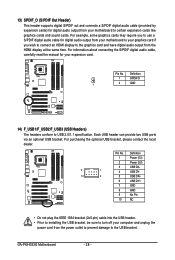
... from the power outlet to prevent damage to turn off your computer and unplug the power cord from the HDMI display at the same time. GA-P43-ES3G Motherboard - 28 - Definition 1 SPDIFO 1 2 GND 14) F_USB1/F_USB2/F_USB3 (USB Headers) The headers conform to certain expansion cards like graphics ... 9 No Pin 10 NC • Do not plug the IEEE 1394 bracket (2x5-pin) cable into the USB header. • Prior to installing the USB bracket, be sure to the USB bracket. For information about connecting the S/PDIF digital audio cable, carefully read the manual for your expansion...
... from the power outlet to prevent damage to turn off your computer and unplug the power cord from the HDMI display at the same time. GA-P43-ES3G Motherboard - 28 - Definition 1 SPDIFO 1 2 GND 14) F_USB1/F_USB2/F_USB3 (USB Headers) The headers conform to certain expansion cards like graphics ... 9 No Pin 10 NC • Do not plug the IEEE 1394 bracket (2x5-pin) cable into the USB header. • Prior to installing the USB bracket, be sure to the USB bracket. For information about connecting the S/PDIF digital audio cable, carefully read the manual for your expansion...


