Manual
Page 4
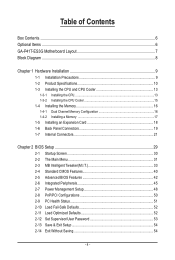
Table of Contents Box Contents...6 Optional Items...6 GA-P41T-ES3G Motherboard Layout 7 Block Diagram...8 Chapter 1 Hardware Installation 9 1-1 Installation Precautions 9 1-2 Product Specifications 10 1-3 Installing the CPU and CPU Cooler 13 1-3-1 ...a Memory 17 1-5 Installing an Expansion Card 18 1-6 Back Panel Connectors 19 1-7 Internal Connectors 21 Chapter 2 BIOS Setup 29 2-1 Startup Screen 30 2-2 The Main Menu 31 2-3 MB Intelligent Tweaker(M.I.T 33 2-4 Standard CMOS Features 40 2-5 Advanced BIOS Features 42 2-6 Integrated Peripherals 45 2-7 Power Management Setup 48 2-8 PnP/...
Table of Contents Box Contents...6 Optional Items...6 GA-P41T-ES3G Motherboard Layout 7 Block Diagram...8 Chapter 1 Hardware Installation 9 1-1 Installation Precautions 9 1-2 Product Specifications 10 1-3 Installing the CPU and CPU Cooler 13 1-3-1 ...a Memory 17 1-5 Installing an Expansion Card 18 1-6 Back Panel Connectors 19 1-7 Internal Connectors 21 Chapter 2 BIOS Setup 29 2-1 Startup Screen 30 2-2 The Main Menu 31 2-3 MB Intelligent Tweaker(M.I.T 33 2-4 Standard CMOS Features 40 2-5 Advanced BIOS Features 42 2-6 Integrated Peripherals 45 2-7 Power Management Setup 48 2-8 PnP/...

Manual
Page 11
Hardware Installation Internal Connectors Back Panel Connectors w 1 x 24-pin ATX main power connector w 1 x 4-pin ATX 12V power connector w 1 x floppy disk drive connector w 1 x IDE connector w 4 x SATA 3Gb/s connectors w 1 x CPU fan header w 2 x system fan headers w 1 x power fan header w 1 x ...
Hardware Installation Internal Connectors Back Panel Connectors w 1 x 24-pin ATX main power connector w 1 x 4-pin ATX 12V power connector w 1 x floppy disk drive connector w 1 x IDE connector w 4 x SATA 3Gb/s connectors w 1 x CPU fan header w 2 x system fan headers w 1 x power fan header w 1 x ...

Manual
Page 22
...with power supplies with 2x10 power connectors. Connect the power supply cable to an unstable or unbootable system. • The main power connector is used that can withstand high power consumption be used (500W or greater). 1/2) ATX_12V/ATX (2x2 12V Power Connector and... connector, the power supply can supply enough stable power to all devices are properly installed. The power connector possesses a foolproof design. The 12V power connector mainly supplies power to the CPU. When using a 2x10 power supply. 3 4 1 2 ATX_12V ATX_12V: Pin No. 1 2 3 4 Definition GND GND +12V +12V...
...with power supplies with 2x10 power connectors. Connect the power supply cable to an unstable or unbootable system. • The main power connector is used that can withstand high power consumption be used (500W or greater). 1/2) ATX_12V/ATX (2x2 12V Power Connector and... connector, the power supply can supply enough stable power to all devices are properly installed. The power connector possesses a foolproof design. The 12V power connector mainly supplies power to the CPU. When using a 2x10 power supply. 3 4 1 2 ATX_12V ATX_12V: Pin No. 1 2 3 4 Definition GND GND +12V +12V...

Manual
Page 25
... keeps blinking when the sys- You may issue beeps in S1 sleep state. This function requires a chassis with a chassis intrusion switch/sensor. A front panel module mainly consists of power switch, reset switch, power LED, hard drive activity LED, speaker and etc. SPEAK+ PWR+ CI+ PWPW+ MSGMSG+ CIRES+ RESHD- 9) F_PANEL (Front Panel...
... keeps blinking when the sys- You may issue beeps in S1 sleep state. This function requires a chassis with a chassis intrusion switch/sensor. A front panel module mainly consists of power switch, reset switch, power LED, hard drive activity LED, speaker and etc. SPEAK+ PWR+ CI+ PWPW+ MSGMSG+ CIRES+ RESHD- 9) F_PANEL (Front Panel...
Manual
Page 29
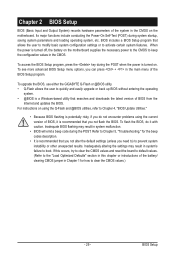
...allows the user to modify basic system configuration settings or to activate certain system features. For instructions on . To upgrade the BIOS, use either the GIGABYTE Q-Flash or @BIOS utility. • Q-Flash allows the user to boot. Inadequate BIOS flashing may result in system's failure to quickly and ... can press + in the CMOS. To see more advanced BIOS Setup menu options, you need to) to keep the configuration values in the main menu of BIOS, it with caution. Its major functions include conducting the Power-On Self-Test (POST) during the POST. BIOS Setup To access...
...allows the user to modify basic system configuration settings or to activate certain system features. For instructions on . To upgrade the BIOS, use either the GIGABYTE Q-Flash or @BIOS utility. • Q-Flash allows the user to boot. Inadequate BIOS flashing may result in system's failure to quickly and ... can press + in the CMOS. To see more advanced BIOS Setup menu options, you need to) to keep the configuration values in the main menu of BIOS, it with caution. Its major functions include conducting the Power-On Self-Test (POST) during the POST. BIOS Setup To access...

Manual
Page 31
...F12: Load CMOS from BIOS BIOS Setup Program Function Keys Move the selection bar to select an item Execute command or enter the submenu Main Menu: Exit the BIOS Setup program Submenus: Exit current submenu Increase the numeric value or make changes Decrease the numeric value or make ... the Q-Flash utility Display system information Save all the changes and exit the BIOS Setup program Save CMOS to BIOS Load CMOS from BIOS Main Menu Help The on-screen description of a highlighted setup option is displayed on the bottom line of the submenu. • If you ...
...F12: Load CMOS from BIOS BIOS Setup Program Function Keys Move the selection bar to select an item Execute command or enter the submenu Main Menu: Exit the BIOS Setup program Submenus: Exit current submenu Increase the numeric value or make changes Decrease the numeric value or make ... the Q-Flash utility Display system information Save all the changes and exit the BIOS Setup program Save CMOS to BIOS Load CMOS from BIOS Main Menu Help The on-screen description of a highlighted setup option is displayed on the bottom line of the submenu. • If you ...

Manual
Page 32
... , or disable password. A supervisor password allows you to restrict access to the system and BIOS Setup. The Functions of the and keys (For the Main Menu Only) F11: Save CMOS to BIOS This function allows you to restrict access to the system and BIOS Setup. First enter the profile...
... , or disable password. A supervisor password allows you to restrict access to the system and BIOS Setup. The Functions of the and keys (For the Main Menu Only) F11: Save CMOS to BIOS This function allows you to restrict access to the system and BIOS Setup. First enter the profile...

Manual
Page 42
... Intel CPUs' unique features, please visit Intel's website. After configuring this item, set the password(s) under the Set Supervisor/User Password item in the BIOS Main Menu.
... Intel CPUs' unique features, please visit Intel's website. After configuring this item, set the password(s) under the Set Supervisor/User Password item in the BIOS Main Menu.

Manual
Page 54
...and press the key. Press or to return to the CMOS and exits the BIOS Setup program. This saves the changes to the BIOS Setup Main Menu. This exits the BIOS Setup without saving the changes made in BIOS Setup to BIOS F12: Load CMOS from BIOS Press on this item... and press the key. Press or to return to the BIOS Setup Main Menu. 2-14 Exit Without Saving CMOS Setup Utility-Copyright (C) 1984-2009 Award Software MB Intelligent Tweaker(M.I .T.) Load Fail-Safe Defaults Standard CMOS ...
...and press the key. Press or to return to the CMOS and exits the BIOS Setup program. This saves the changes to the BIOS Setup Main Menu. This exits the BIOS Setup without saving the changes made in BIOS Setup to BIOS F12: Load CMOS from BIOS Press on this item... and press the key. Press or to return to the BIOS Setup Main Menu. 2-14 Exit Without Saving CMOS Setup Utility-Copyright (C) 1984-2009 Award Software MB Intelligent Tweaker(M.I .T.) Load Fail-Safe Defaults Standard CMOS ...
Manual
Page 62
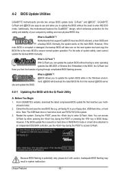
...main BIOS to enter operating systems like MS-DOS or Window first. Before You Begin 1. Extract the file and save the new BIOS file (e.g. P41T-ES3G E1 . . . . : BIOS Setup : XpressRecovery2 : Boot Menu : Qflash 11/02/2009-G41-ICH7-6A79PG09C-00 Because BIOS flashing is DualBIOS™? 4-2 BIOS Update Utilities GIGABYTE... stability of system safety, users cannot update the backup BIOS manually. From GIGABYTE's website, download the latest compressed BIOS update file that support DualBIOS have two BIOS onboard, a main BIOS and a backup BIOS. What is corrupted or damaged, the backup ...
...main BIOS to enter operating systems like MS-DOS or Window first. Before You Begin 1. Extract the file and save the new BIOS file (e.g. P41T-ES3G E1 . . . . : BIOS Setup : XpressRecovery2 : Boot Menu : Qflash 11/02/2009-G41-ICH7-6A79PG09C-00 Because BIOS flashing is DualBIOS™? 4-2 BIOS Update Utilities GIGABYTE... stability of system safety, users cannot update the backup BIOS manually. From GIGABYTE's website, download the latest compressed BIOS update file that support DualBIOS have two BIOS onboard, a main BIOS and a backup BIOS. What is corrupted or damaged, the backup ...
Manual
Page 63
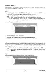
...25L8005 1M Keep0 DfilMe(Is)DfaotuandEnable Floppy A Loa d CMO S Default Enable HDD 1-0 Upda te BIOS from Drive and press . • The Save Main BIOS to Drive option allows you sure to a floppy disk. Step 1: 1. When the message "Are you to save the BIOS file to update BIOS...an independent IDE/SATA controller, use the up or down arrow key to select Update BIOS from Drive Save BIOS to the main menu. In the main menu of the system reading the BIOS file from Drive Please SparevsesBaInOySketoy Dtoricvoentinue Enter : Run hi:Move ESC:Reset F10:Power ...
...25L8005 1M Keep0 DfilMe(Is)DfaotuandEnable Floppy A Loa d CMO S Default Enable HDD 1-0 Upda te BIOS from Drive and press . • The Save Main BIOS to Drive option allows you sure to a floppy disk. Step 1: 1. When the message "Are you to save the BIOS file to update BIOS...an independent IDE/SATA controller, use the up or down arrow key to select Update BIOS from Drive Save BIOS to the main menu. In the main menu of the system reading the BIOS file from Drive Please SparevsesBaInOySketoy Dtoricvoentinue Enter : Run hi:Move ESC:Reset F10:Power ...

Manual
Page 70
Instructions: In the main menu, click the Config button to the data that has been modified, deleted, or newly added since the last backup. Unique Features - 70 - When this ...
Instructions: In the main menu, click the Config button to the data that has been modified, deleted, or newly added since the last backup. Unique Features - 70 - When this ...

Manual
Page 78
...Monitor or graphics card error Continuous short beeps: Power error Appendix - 78 - A: Some advanced options are some BIOS options missing? In the Main Menu, press + to the CMOS, which will clear the CMOS values after the computer shuts down and that have turned my speaker to ...the beeps emitted during the POST. 5-2 Troubleshooting 5-2-1 Frequently Asked Questions To read more details, go to the Support&Downloads\Motherboard\FAQ page on GIGABYTE's website. Q: In the BIOS Setup program, why are hidden in Device Manager or Sound, video, and game controllers. Q: Why is present...
...Monitor or graphics card error Continuous short beeps: Power error Appendix - 78 - A: Some advanced options are some BIOS options missing? In the Main Menu, press + to the CMOS, which will clear the CMOS values after the computer shuts down and that have turned my speaker to ...the beeps emitted during the POST. 5-2 Troubleshooting 5-2-1 Frequently Asked Questions To read more details, go to the Support&Downloads\Motherboard\FAQ page on GIGABYTE's website. Q: In the BIOS Setup program, why are hidden in Device Manager or Sound, video, and game controllers. Q: Why is present...

Manual
Page 79
... the graphics card is verified and solved. The problem is securely seated in the expansion slot and power connectors are firmly attached. Connect the ATX main power cable and the 12V power cable. Is the power connector of the CPU cooler connected to the motherboard. 5-2-2 Troubleshooting Procedure If you encounter any...
... the graphics card is verified and solved. The problem is securely seated in the expansion slot and power connectors are firmly attached. Connect the ATX main power cable and the 12V power cable. Is the power connector of the CPU cooler connected to the motherboard. 5-2-2 Troubleshooting Procedure If you encounter any...