Manual
Page 45
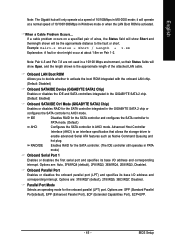
...environment, so their Status fields will be the approximate distance to AHCI mode. IDE AHCI Disables RAID for the SATA controller integrated in the GIGABYTE SATA 2 chip or configures the SATA controller to the fault or short. Onboard Parallel Port Enables or disables the onboard parallel port (LPT)...Enables RAID for the onboard parallel (LPT) port. BIOS Setup English Note: The Gigabit hub will operate at a normal speed of 10/100/1000Mbps in Windows mode or when the LAN Boot ROM is the approximate length of the attached LAN cable. it will only operate at about 1.6m ...
...environment, so their Status fields will be the approximate distance to AHCI mode. IDE AHCI Disables RAID for the SATA controller integrated in the GIGABYTE SATA 2 chip or configures the SATA controller to the fault or short. Onboard Parallel Port Enables or disables the onboard parallel port (LPT)...Enables RAID for the onboard parallel (LPT) port. BIOS Setup English Note: The Gigabit hub will operate at a normal speed of 10/100/1000Mbps in Windows mode or when the LAN Boot ROM is the approximate length of the attached LAN cable. it will only operate at about 1.6m ...
Manual
Page 61
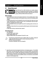
...; 2000 with Xpress Recovery cannot be restored using Xpress Recovery2. • USB hard drives are not supported. • Hard drives in advanced (10 GB or more is backed up/restored. • It takes longer to back up /restore the first physical hard drive that allows you to back ... RAID/AHCI mode are attached to the first and second SATA connectors, the hard drive on the first IDE connector is the first physical drive. Windows® XP with SP1 or later • Xpress Recovery and Xpress Recovery2 are installed. • The amount of data). • It is recommended to quickly...
...; 2000 with Xpress Recovery cannot be restored using Xpress Recovery2. • USB hard drives are not supported. • Hard drives in advanced (10 GB or more is backed up/restored. • It takes longer to back up /restore the first physical hard drive that allows you to back ... RAID/AHCI mode are attached to the first and second SATA connectors, the hard drive on the first IDE connector is the first physical drive. Windows® XP with SP1 or later • Xpress Recovery and Xpress Recovery2 are installed. • The amount of data). • It is recommended to quickly...

Manual
Page 62
English Installation and Configuration (The following procedure uses Windows XP as the first boot device under "Advanced BIOS Features" in the BIOS Setup program. When partitioning your hard drive (Figure 1), make sure to leave ... drive as the example operating system.) A. actual size requirements vary, depending on the amount of the operating system (Figure 3). Select a file system (for Xpress Recovery2 (10 GB or more is recommended; Save the changes and exit. 2. Installing Windows XP and Partitioning the Hard Drive 1. Figure 3 GA-P35-DS3P Motherboard - 62 -
English Installation and Configuration (The following procedure uses Windows XP as the first boot device under "Advanced BIOS Features" in the BIOS Setup program. When partitioning your hard drive (Figure 1), make sure to leave ... drive as the example operating system.) A. actual size requirements vary, depending on the amount of the operating system (Figure 3). Select a file system (for Xpress Recovery2 (10 GB or more is recommended; Save the changes and exit. 2. Installing Windows XP and Partitioning the Hard Drive 1. Figure 3 GA-P35-DS3P Motherboard - 62 -

Manual
Page 64
... this hard drive contains the Windows operating system. Figure 8 2. Award Modular BIOS v6.00PG, An Energy Star Ally Copyright (C) 1984-2007, Award Software, Inc. Using the Backup Function in Xpress Recovery2 for the first time, Xpress Recovery2 will begin to startup XpressRecovery2..... Figure 10 Figure 11 3. Figure 12 GA-P35-DS3P Motherboard Xpress Recovery2 will...
... this hard drive contains the Windows operating system. Figure 8 2. Award Modular BIOS v6.00PG, An Energy Star Ally Copyright (C) 1984-2007, Award Software, Inc. Using the Backup Function in Xpress Recovery2 for the first time, Xpress Recovery2 will begin to startup XpressRecovery2..... Figure 10 Figure 11 3. Figure 12 GA-P35-DS3P Motherboard Xpress Recovery2 will...
Manual
Page 71
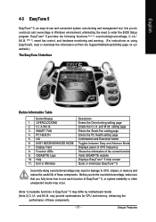
...doing overclock/overvoltage may result in damage to CPU, chipset, or memory and reduce the useful life of these components. - 71 - GO 6. GIGABYTE Logo 10. PC HEALTH 5. Function LEDs 9. Help 11. Before you do the overclock/overvoltage, make sure that you fully know how to use and convenient... system overclocking and management tool, lets you do overclock and overvoltage in Windows environment, eliminating the need to enter the BIOS Setup program....
...doing overclock/overvoltage may result in damage to CPU, chipset, or memory and reduce the useful life of these components. - 71 - GO 6. GIGABYTE Logo 10. PC HEALTH 5. Function LEDs 9. Help 11. Before you do the overclock/overvoltage, make sure that you fully know how to use and convenient... system overclocking and management tool, lets you do overclock and overvoltage in Windows environment, eliminating the need to enter the BIOS Setup program....

Manual
Page 84
... array. N RAID Level Capacity Status 0-Stripe 240 GB Normal Members(HDDx) 01 [KL]-Select RAID GA-P35-DS3P Motherboard [SPACE]-Mark Delete [DEL]-Confirm Figure 11 - 84 - [ESC]-Abort PCIE-to-SATAII/IDE...RAID Level 0-Stripe Capacity Status 240 GB Normal Members(HDDx) 01 [IJTAB]-Switch Window [KL]-Select ITEM [ENTER]-Action Figure 10 [ESC]-Exit Now, you may proceed to the RAID Disk Drive List block. ... then press (Figure 10). Save and Exit Setup: After configuring the RAID array, select the Save And Exit Setup item in the main menu and press . GIGABYTE Technology Corp. a ...
... array. N RAID Level Capacity Status 0-Stripe 240 GB Normal Members(HDDx) 01 [KL]-Select RAID GA-P35-DS3P Motherboard [SPACE]-Mark Delete [DEL]-Confirm Figure 11 - 84 - [ESC]-Abort PCIE-to-SATAII/IDE...RAID Level 0-Stripe Capacity Status 240 GB Normal Members(HDDx) 01 [IJTAB]-Switch Window [KL]-Select ITEM [ENTER]-Action Figure 10 [ESC]-Exit Now, you may proceed to the RAID Disk Drive List block. ... then press (Figure 10). Save and Exit Setup: After configuring the RAID array, select the Save And Exit Setup item in the main menu and press . GIGABYTE Technology Corp. a ...


