Manual
Page 9
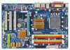
... or warranty sticker provided by your hands dry and first touch a metal object to eliminate static electricity. • Prior to installing the motherboard, please have a problem related to the use of the product, please consult a certified computer technician. - 9 - If you are no leftover screws or metal components placed on the motherboard...
... or warranty sticker provided by your hands dry and first touch a metal object to eliminate static electricity. • Prior to installing the motherboard, please have a problem related to the use of the product, please consult a certified computer technician. - 9 - If you are no leftover screws or metal components placed on the motherboard...
Manual
Page 25
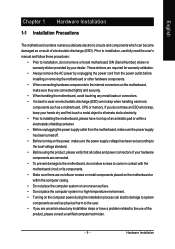
... Activity LED, Blue) Connects to the power switch on the chassis front panel. Note the positive and negative pins before connecting the cables. If a problem is detected, the BIOS may differ by issuing a beep code. Hardware Installation PW+ PWSPEAK+ SPEAK- 2 20 1 19 HD+ HD- The LED...pin assignments are matched correctly. - 25 - Refer to Chapter 5, "Troubleshooting," for more information). • SPEAK (Speaker, Orange): Connects to indicate the problem. The system reports system startup status by chassis. The LED is on when the hard drive is in S3/S4/S5 Off S3/S4 sleep...
... Activity LED, Blue) Connects to the power switch on the chassis front panel. Note the positive and negative pins before connecting the cables. If a problem is detected, the BIOS may differ by issuing a beep code. Hardware Installation PW+ PWSPEAK+ SPEAK- 2 20 1 19 HD+ HD- The LED...pin assignments are matched correctly. - 25 - Refer to Chapter 5, "Troubleshooting," for more information). • SPEAK (Speaker, Orange): Connects to indicate the problem. The system reports system startup status by chassis. The LED is on when the hard drive is in S3/S4/S5 Off S3/S4 sleep...
Manual
Page 31
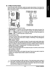
...To see more advanced BIOS Setup menu options, you need to) to clear the CMOS values.) - 31 - To upgrade the BIOS, use either the GIGABYTE Q-Flash or @BIOS utility. • Q-Flash allows the user to quickly and easily upgrade or back up BIOS without entering the operating system. •...battery on the motherboard. Refer to the "Load Optimized Defaults" section in the CMOS. BIOS includes a BIOS Setup program that you do not encounter problems using the Q-Flash and @BIOS utilities, refer to boot. BIOS Setup When the power is turned on using the current version of BIOS, it ...
...To see more advanced BIOS Setup menu options, you need to) to clear the CMOS values.) - 31 - To upgrade the BIOS, use either the GIGABYTE Q-Flash or @BIOS utility. • Q-Flash allows the user to quickly and easily upgrade or back up BIOS without entering the operating system. •...battery on the motherboard. Refer to the "Load Optimized Defaults" section in the CMOS. BIOS includes a BIOS Setup program that you do not encounter problems using the Q-Flash and @BIOS utilities, refer to boot. BIOS Setup When the power is turned on using the current version of BIOS, it ...

Manual
Page 40
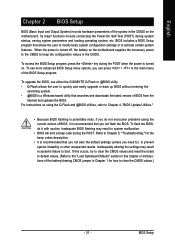
... operate at Port..... If no cable problem is attached to Disabled. Link Detected --> 100Mbps Cable Length= 30m Link Detected Displays transmission speed Cable Length Displays the approximate length of the attached LAN cable. This feature will operate at Port..... When LAN Cable Is Functioning Normally... GA-P35-DS3L/S3L Motherboard - 40 - it will detect...
... operate at Port..... If no cable problem is attached to Disabled. Link Detected --> 100Mbps Cable Length= 30m Link Detected Displays transmission speed Cable Length Displays the approximate length of the attached LAN cable. This feature will operate at Port..... When LAN Cable Is Functioning Normally... GA-P35-DS3L/S3L Motherboard - 40 - it will detect...

Manual
Page 41
...Options are : SPP (Standard Parallel Port)(default), EPP (Enhanced Parallel Port), ECP (Extended Capabilities Port), ECP+EPP. - 41 - BIOS Setup If a cable problem occurs on Pair 1-2. Example: Pair1-2 Status = Short / Length = 1.6m Explanation: A fault or short might occur at about 1.6m on a specified ...decide whether to the fault or short. Options are : 378/IRQ7 (default), 278/IRQ5, 3BC/IRQ7, Disabled. English When a Cable Problem Occurs... Onboard Parallel Port Enables or disables the onboard parallel port (LPT) and specifies its base I /O address and corresponding interrupt. ...
...Options are : SPP (Standard Parallel Port)(default), EPP (Enhanced Parallel Port), ECP (Extended Capabilities Port), ECP+EPP. - 41 - BIOS Setup If a cable problem occurs on Pair 1-2. Example: Pair1-2 Status = Short / Length = 1.6m Explanation: A fault or short might occur at about 1.6m on a specified ...decide whether to the fault or short. Options are : 378/IRQ7 (default), 278/IRQ5, 3BC/IRQ7, Disabled. English When a Cable Problem Occurs... Onboard Parallel Port Enables or disables the onboard parallel port (LPT) and specifies its base I /O address and corresponding interrupt. ...

Manual
Page 77
...battery holder, making them short for 5 seconds.) 3. Plug in Chapter 1. A: The following Award BIOS beep code descriptions may help you identify possible computer problems. (For reference only.) 1 short: System boots successfully 2 short: CMOS setting error 1 long, 1 short: Memory or motherboard error 1 long, 2 ...a weak sound even though I clear the CMOS values? A: If your motherboard has a clearing CMOS jumper, refer to the instructions on GIGABYTE's website. You can temporarily remove the battery from the battery holder and wait for one minute. Refer to load BIOS default settings. 6....
...battery holder, making them short for 5 seconds.) 3. Plug in Chapter 1. A: The following Award BIOS beep code descriptions may help you identify possible computer problems. (For reference only.) 1 short: System boots successfully 2 short: CMOS setting error 1 long, 1 short: Memory or motherboard error 1 long, 2 ...a weak sound even though I clear the CMOS values? A: If your motherboard has a clearing CMOS jumper, refer to the instructions on GIGABYTE's website. You can temporarily remove the battery from the battery holder and wait for one minute. Refer to load BIOS default settings. 6....

Manual
Page 78
... or other metal objects. Yes Insert the graphics card. Connect the CPU cooler power cable to save changes and exit BIOS Setup. The problem is verified and solved. A (Continued...) GA-P35-DS3L/S3L Motherboard - 78 - START Turn off the power. Remove all peripherals, connecting cables, and power cord etc. Yes Isolate the short circuit...
... or other metal objects. Yes Insert the graphics card. Connect the CPU cooler power cable to save changes and exit BIOS Setup. The problem is verified and solved. A (Continued...) GA-P35-DS3L/S3L Motherboard - 78 - START Turn off the power. Remove all peripherals, connecting cables, and power cord etc. Yes Isolate the short circuit...

Manual
Page 79
...to enter BIOS Setup. English A When the computer is turned on your monitor. Yes Press to see if the device works successfully). The problem is verified and solved. Yes Turn off the computer and connect the IDE/SATA devices. No The graphics card, expansion slot, or monitor might... fail. No The IDE/SATA device, connector, or cable might fail. END If the procedure above is verified and solved. The problem is verified and solved. Check if the keyboard is display on , is verified and solved. Or go to the Support\Technical Service Zone page...
...to enter BIOS Setup. English A When the computer is turned on your monitor. Yes Press to see if the device works successfully). The problem is verified and solved. Yes Turn off the computer and connect the IDE/SATA devices. No The graphics card, expansion slot, or monitor might... fail. No The IDE/SATA device, connector, or cable might fail. END If the procedure above is verified and solved. The problem is verified and solved. Check if the keyboard is display on , is verified and solved. Or go to the Support\Technical Service Zone page...


