
Manual
Page 1
GA-P31-DS3/ GA-P31-DS3L/ GA-P31-S3L LGA775 socket motherboard for Intel® CoreTM processor family/ Intel® Pentium® processor family/Intel® Celeron® processor family User's Manual Rev. 1001 12ME-P31DS3-1001R * The WEEE marking on the product indicates this product must not be disposed of with user's other household waste and must be handed over to a designated collection point for the recycling of waste electrical and electronic equipment!! * The WEEE marking applies only in European Union's member states.
GA-P31-DS3/ GA-P31-DS3L/ GA-P31-S3L LGA775 socket motherboard for Intel® CoreTM processor family/ Intel® Pentium® processor family/Intel® Celeron® processor family User's Manual Rev. 1001 12ME-P31DS3-1001R * The WEEE marking on the product indicates this product must not be disposed of with user's other household waste and must be handed over to a designated collection point for the recycling of waste electrical and electronic equipment!! * The WEEE marking applies only in European Union's member states.

Manual
Page 2
Motherboard GA-P31-DS3/GA-P31-DS3L/GA-P31-S3L Jul. 20, 2007 Motherboard GA-P31-DS3/GA-P31-DS3L/ GA-P31-S3L Jul. 20, 2007
Motherboard GA-P31-DS3/GA-P31-DS3L/GA-P31-S3L Jul. 20, 2007 Motherboard GA-P31-DS3/GA-P31-DS3L/ GA-P31-S3L Jul. 20, 2007

Manual
Page 4
Table of Contents Box Contents ...6 OptionalItems ...6 GA-P31-DS3/DS3L/S3L Motherboard Layout 7 Block Diagram ...8 Chapter 1 Hardware Installation 9 1-1 Installation Precautions 9 1-2 Product Specifications 10 1-3 Installing the CPU and CPU Cooler 13 1-3-1 Installing the CPU 13 1-3-2 Installing the ...
Table of Contents Box Contents ...6 OptionalItems ...6 GA-P31-DS3/DS3L/S3L Motherboard Layout 7 Block Diagram ...8 Chapter 1 Hardware Installation 9 1-1 Installation Precautions 9 1-2 Product Specifications 10 1-3 Installing the CPU and CPU Cooler 13 1-3-1 Installing the CPU 13 1-3-2 Installing the ...

Manual
Page 6
... USB 2.0 bracket (Part No. 12CR1-1UB030-21/R) SATA bracket (Part No. 12CF1-3SATPW-11R ) S/PDIF in cable (Part No. 12CR1-1SPDIN-01/R) - 6 - Box Contents GA-P31-DS3, GA-P31-DS3L or GA-P31-S3L motherboard Motherboard driver disk User's Manual Quick Installation Guide Intel® LGA775 CPU Installation Guide One IDE cable and one floppy disk drive cable...
... USB 2.0 bracket (Part No. 12CR1-1UB030-21/R) SATA bracket (Part No. 12CF1-3SATPW-11R ) S/PDIF in cable (Part No. 12CR1-1SPDIN-01/R) - 6 - Box Contents GA-P31-DS3, GA-P31-DS3L or GA-P31-S3L motherboard Motherboard driver disk User's Manual Quick Installation Guide Intel® LGA775 CPU Installation Guide One IDE cable and one floppy disk drive cable...

Manual
Page 7
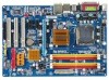
GA-P31-DS3/DS3L/S3L Motherboard Layout KB_MS COAXIAL OPTICAL ATX_12V LGA775 CPU_FAN COMA LPT PWR_FAN GA-P31-DS3/DS3L/S3L USB USB LAN F_AUDIO Intel® P31 AUDIO SYS_FAN1 DDRII1 PCIE_3 ATX CD_IN RTL8111B PCIE_16 DDRII2 DDRII3 DDRII4 PCIE_1 CLR_CMOS SPDIF_O CODEC PCIE_2 PCI1 SPDIF_I PCI2 IT8718 PCI3 CI FDD Intel® ICH7 BAT SATAII0 SATAII2 SYS_FAN2 BIOS SATAII1 SATAII3 IDE1 PWR_LED F_PANEL F_USB1 F_USB2 "*" Only the GA-P31-DS3/DS3L adopts All-Solid Capacitor design. - 7 -
GA-P31-DS3/DS3L/S3L Motherboard Layout KB_MS COAXIAL OPTICAL ATX_12V LGA775 CPU_FAN COMA LPT PWR_FAN GA-P31-DS3/DS3L/S3L USB USB LAN F_AUDIO Intel® P31 AUDIO SYS_FAN1 DDRII1 PCIE_3 ATX CD_IN RTL8111B PCIE_16 DDRII2 DDRII3 DDRII4 PCIE_1 CLR_CMOS SPDIF_O CODEC PCIE_2 PCI1 SPDIF_I PCI2 IT8718 PCI3 CI FDD Intel® ICH7 BAT SATAII0 SATAII2 SYS_FAN2 BIOS SATAII1 SATAII3 IDE1 PWR_LED F_PANEL F_USB1 F_USB2 "*" Only the GA-P31-DS3/DS3L adopts All-Solid Capacitor design. - 7 -

Manual
Page 10
...174; Pentium® 4 processor/ Intel® Celeron® processor in the LGA 775 package (Go to GIGABYTE's website for the latest CPU support list.) Š Support for Intel® Hyper-Threading Technology Š L2...138; Dual channel memory architecture Š Support for DDR2 800/667 MHz memory modules (Note 2) (Go to GIGABYTE's website for the latest memory support list.) Š Realtek ALC888 codec Š High Definition Audio Š 2/4/5.1/7.1-... connected to the internal USB headers) "*" Only the GA-P31-DS3/DS3L adopts All-Solid Capacitor design. GA-P31-DS3/DS3L/S3L Motherboard - 10 -
...174; Pentium® 4 processor/ Intel® Celeron® processor in the LGA 775 package (Go to GIGABYTE's website for the latest CPU support list.) Š Support for Intel® Hyper-Threading Technology Š L2...138; Dual channel memory architecture Š Support for DDR2 800/667 MHz memory modules (Note 2) (Go to GIGABYTE's website for the latest memory support list.) Š Realtek ALC888 codec Š High Definition Audio Š 2/4/5.1/7.1-... connected to the internal USB headers) "*" Only the GA-P31-DS3/DS3L adopts All-Solid Capacitor design. GA-P31-DS3/DS3L/S3L Motherboard - 10 -
Manual
Page 12
GA-P31-DS3/DS3L/S3L Motherboard - 12 - For example, 4 GB of memory is reserved for more information.) (Note 3) Available functions in memory frequency being reduced from the original frequency. (Please ...
GA-P31-DS3/DS3L/S3L Motherboard - 12 - For example, 4 GB of memory is reserved for more information.) (Note 3) Available functions in memory frequency being reduced from the original frequency. (Please ...

Manual
Page 14
... socket cover. Follow the steps below to the CPU. Step 4: Hold the CPU with the socket alignment keys) and gently insert the CPU into position. GA-P31-DS3/DS3L/S3L Motherboard - 14 - Step 3: Lift the metal load plate on the CPU socket. Align the CPU pin one marking (triangle) with the pin one corner...
... socket cover. Follow the steps below to the CPU. Step 4: Hold the CPU with the socket alignment keys) and gently insert the CPU into position. GA-P31-DS3/DS3L/S3L Motherboard - 14 - Step 3: Lift the metal load plate on the CPU socket. Align the CPU pin one marking (triangle) with the pin one corner...

Manual
Page 16
... results may occur. DS/SS - - DS/SS - - - - DDRII1 DDRII2 DDRII3 DDRII4 Two Modules SS SS - - - - - - - - GA-P31-DS3/DS3L/S3L Motherboard - 16 - SS SS - - Dual Channel mode cannot be used . (Go to start or incorrect detection of the same channel (e.g. After the memory is...- - DS/SS - - However, when using a FSB 1333 MHz CPU with double-sided memory modules to prevent system's failure to GIGABYTE's website for optimum performance. 3. DDRII1 and DDRII2) with the memory configu- English 1-4 Installing the Memory Read the following : Channel 0:...
... results may occur. DS/SS - - DS/SS - - - - DDRII1 DDRII2 DDRII3 DDRII4 Two Modules SS SS - - - - - - - - GA-P31-DS3/DS3L/S3L Motherboard - 16 - SS SS - - Dual Channel mode cannot be used . (Go to start or incorrect detection of the same channel (e.g. After the memory is...- - DS/SS - - However, when using a FSB 1333 MHz CPU with double-sided memory modules to prevent system's failure to GIGABYTE's website for optimum performance. 3. DDRII1 and DDRII2) with the memory configu- English 1-4 Installing the Memory Read the following : Channel 0:...

Manual
Page 18
... card with a screw. 5. Example: Installing and Removing a PCI Express x16 Graphics Card: • Installing a Graphics Card: Gently insert the graphics card into the slot. 4. GA-P31-DS3/DS3L/S3L Motherboard - 18 - English 1-5 Installing an Expansion Card Read the following guidelines before installing an expansion card to prevent hardware damage. After installing all expansion cards...
... card with a screw. 5. Example: Installing and Removing a PCI Express x16 Graphics Card: • Installing a Graphics Card: Gently insert the graphics card into the slot. 4. GA-P31-DS3/DS3L/S3L Motherboard - 18 - English 1-5 Installing an Expansion Card Read the following guidelines before installing an expansion card to prevent hardware damage. After installing all expansion cards...

Manual
Page 20
... Center/Subwoofer Speaker Out Jack (Orange) Use this audio jack to connect center/subwoofer speakers in jack. This jack can be connected to this jack. GA-P31-DS3/DS3L/S3L Motherboard - 20 - Line In Jack (Blue) The default line in a 5.1/7.1-channel audio configuration.
... Center/Subwoofer Speaker Out Jack (Orange) Use this audio jack to connect center/subwoofer speakers in jack. This jack can be connected to this jack. GA-P31-DS3/DS3L/S3L Motherboard - 20 - Line In Jack (Blue) The default line in a 5.1/7.1-channel audio configuration.

Manual
Page 22
... 3.3V -12V GND PS_ON(soft On/Off) GND GND GND -5V +5V +5V +5V (Only for 2x12-pinATX) GND (Only for 2x12-pin ATX) GA-P31-DS3/DS3L/S3L Motherboard - 22 - The power connector possesses a foolproof design. Before connecting the power connector, first make sure the power supply is recommended that a power supply that...
... 3.3V -12V GND PS_ON(soft On/Off) GND GND GND -5V +5V +5V +5V (Only for 2x12-pinATX) GND (Only for 2x12-pin ATX) GA-P31-DS3/DS3L/S3L Motherboard - 22 - The power connector possesses a foolproof design. Before connecting the power connector, first make sure the power supply is recommended that a power supply that...

Manual
Page 24
... cable, locate the foolproof groove on the connector. SATAII0 SATAII2 7 17 1 1 71 7 SATAII1 SATAII3 Pin No. 1 2 3 4 5 6 7 Definition GND TXP TXN GND RXN RXP GND GA-P31-DS3/DS3L/S3L Motherboard - 24 - If you wish to connect two IDE devices, remember to set the jumpers and the cabling according to the role of the IDE...
... cable, locate the foolproof groove on the connector. SATAII0 SATAII2 7 17 1 1 71 7 SATAII1 SATAII3 Pin No. 1 2 3 4 5 6 7 Definition GND TXP TXN GND RXN RXP GND GA-P31-DS3/DS3L/S3L Motherboard - 24 - If you wish to connect two IDE devices, remember to set the jumpers and the cabling according to the role of the IDE...
Manual
Page 26
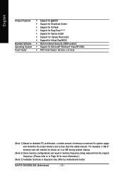
... (S5). • PW (Power Switch, Red): Connects to the power status indicator on the chassis front panel. If a problem is in S1 sleep state. GA-P31-DS3/DS3L/S3L Motherboard - 26 - RESRES+ NC IDE Hard Disk Reset Active LED Switch • MSG (Message/Power/Sleep LED, Yellow): System Status LED Connects to the power...
... (S5). • PW (Power Switch, Red): Connects to the power status indicator on the chassis front panel. If a problem is in S1 sleep state. GA-P31-DS3/DS3L/S3L Motherboard - 26 - RESRES+ NC IDE Hard Disk Reset Active LED Switch • MSG (Message/Power/Sleep LED, Yellow): System Status LED Connects to the power...

Manual
Page 28
GA-P31-DS3/DS3L/S3L Motherboard - 28 - For information about connecting the S/PDIF digital audio cable, carefully read the manual for your motherboard to the USB bracket. English 15) SPDIF_O (S/...
GA-P31-DS3/DS3L/S3L Motherboard - 28 - For information about connecting the S/PDIF digital audio cable, carefully read the manual for your motherboard to the USB bracket. English 15) SPDIF_O (S/...
Manual
Page 30
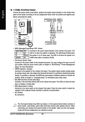
... battery, note the orientation of the positive side (+) and the negative side (-) of the battery holder, making them short for one . You may be lost. GA-P31-DS3/DS3L/S3L Motherboard - 30 - Replace the battery. 4. Gently remove the battery from the battery holder and wait for 5 seconds.) 3. English 19) BAT(Battery) The battery provides...
... battery, note the orientation of the positive side (+) and the negative side (-) of the battery holder, making them short for one . You may be lost. GA-P31-DS3/DS3L/S3L Motherboard - 30 - Replace the battery. 4. Gently remove the battery from the battery holder and wait for 5 seconds.) 3. English 19) BAT(Battery) The battery provides...

Manual
Page 32
... E14 . . . . : BIOS Setup/Q-Flash : XpressRecovery2 : Boot Menu : Qflash 07/02/2007-P31-ICH7-6A79OG0WC-00 Function Keys Function Keys: : POST Screen Press the key to show the BIOS POST screen at system startup, refer to the instructions ... key < > or the down arrow key< > to select the first boot device, then press to enter BIOS Setup first. Note: The setting in Boot Menu. GA-P31-DS3/DS3L/S3L Motherboard - 32 - A.
... E14 . . . . : BIOS Setup/Q-Flash : XpressRecovery2 : Boot Menu : Qflash 07/02/2007-P31-ICH7-6A79OG0WC-00 Function Keys Function Keys: : POST Screen Press the key to show the BIOS POST screen at system startup, refer to the instructions ... key < > or the down arrow key< > to select the first boot device, then press to enter BIOS Setup first. Note: The setting in Boot Menu. GA-P31-DS3/DS3L/S3L Motherboard - 32 - A.

Manual
Page 34
... for optimal-performance system operations. „ Set Supervisor Password Change, set , or disable password. First select the profile you can also carry out this task.) GA-P31-DS3/DS3L/S3L Motherboard - 34 - A supervisor password allows you to restrict access to the system and BIOS Setup. English „ The Functions of the and keys (For...
... for optimal-performance system operations. „ Set Supervisor Password Change, set , or disable password. First select the profile you can also carry out this task.) GA-P31-DS3/DS3L/S3L Motherboard - 34 - A supervisor password allows you to restrict access to the system and BIOS Setup. English „ The Functions of the and keys (For...

Manual
Page 36
... system. Head Number of the currently installed hard drive. Precomp Write precompensation cylinder. Total Memory The total amount of memory installed on the hard drive. GA-P31-DS3/DS3L/S3L Motherboard - 36 -
... system. Head Number of the currently installed hard drive. Precomp Write precompensation cylinder. Total Memory The total amount of memory installed on the hard drive. GA-P31-DS3/DS3L/S3L Motherboard - 36 -

Manual
Page 38
...one computer system can dynamically and effectively lower the CPU voltage and core frequency to Enabled for operating systems that supports this feature. GA-P31-DS3/DS3L/S3L Motherboard - 38 - This feature only works for legacy operating system such as the first display. (Note) This item is ...When enabled, the CPU core frequency and voltage will allow a platform to Disabled for the computer, reducing exposure to display the GIGABYTE Logo at system startup. Disabled displays normal POST message. (Default: Enabled) Init Display First Specifies the first initiation of the...
...one computer system can dynamically and effectively lower the CPU voltage and core frequency to Enabled for operating systems that supports this feature. GA-P31-DS3/DS3L/S3L Motherboard - 38 - This feature only works for legacy operating system such as the first display. (Note) This item is ...When enabled, the CPU core frequency and voltage will allow a platform to Disabled for the computer, reducing exposure to display the GIGABYTE Logo at system startup. Disabled displays normal POST message. (Default: Enabled) Init Display First Specifies the first initiation of the...