
Manual
Page 1
GA-P31-DS3/ GA-P31-DS3L/ GA-P31-S3L LGA775 socket motherboard for Intel® CoreTM processor family/ Intel® Pentium® processor family/Intel® Celeron® processor family User's Manual Rev. 1001 12ME-P31DS3-1001R * The WEEE marking on the product indicates this product must not be disposed of with user's other household waste and must be handed over to a designated collection point for the recycling of waste electrical and electronic equipment!! * The WEEE marking applies only in European Union's member states.
GA-P31-DS3/ GA-P31-DS3L/ GA-P31-S3L LGA775 socket motherboard for Intel® CoreTM processor family/ Intel® Pentium® processor family/Intel® Celeron® processor family User's Manual Rev. 1001 12ME-P31DS3-1001R * The WEEE marking on the product indicates this product must not be disposed of with user's other household waste and must be handed over to a designated collection point for the recycling of waste electrical and electronic equipment!! * The WEEE marking applies only in European Union's member states.

Manual
Page 2
Motherboard GA-P31-DS3/GA-P31-DS3L/GA-P31-S3L Jul. 20, 2007 Motherboard GA-P31-DS3/GA-P31-DS3L/ GA-P31-S3L Jul. 20, 2007
Motherboard GA-P31-DS3/GA-P31-DS3L/GA-P31-S3L Jul. 20, 2007 Motherboard GA-P31-DS3/GA-P31-DS3L/ GA-P31-S3L Jul. 20, 2007

Manual
Page 4
Table of Contents Box Contents ...6 OptionalItems ...6 GA-P31-DS3/DS3L/S3L Motherboard Layout 7 Block Diagram ...8 Chapter 1 Hardware Installation 9 1-1 Installation Precautions 9 1-2 Product Specifications 10 1-3 Installing the CPU and CPU Cooler 13 1-3-1 Installing the CPU 13 1-3-2 Installing ...
Table of Contents Box Contents ...6 OptionalItems ...6 GA-P31-DS3/DS3L/S3L Motherboard Layout 7 Block Diagram ...8 Chapter 1 Hardware Installation 9 1-1 Installation Precautions 9 1-2 Product Specifications 10 1-3 Installing the CPU and CPU Cooler 13 1-3-1 Installing the CPU 13 1-3-2 Installing ...

Manual
Page 6
... USB 2.0 bracket (Part No. 12CR1-1UB030-21/R) SATA bracket (Part No. 12CF1-3SATPW-11R ) S/PDIF in cable (Part No. 12CR1-1SPDIN-01/R) - 6 - Box Contents GA-P31-DS3, GA-P31-DS3L or GA-P31-S3L motherboard Motherboard driver disk User's Manual Quick Installation Guide Intel® LGA775 CPU Installation Guide One IDE cable and one floppy disk drive...
... USB 2.0 bracket (Part No. 12CR1-1UB030-21/R) SATA bracket (Part No. 12CF1-3SATPW-11R ) S/PDIF in cable (Part No. 12CR1-1SPDIN-01/R) - 6 - Box Contents GA-P31-DS3, GA-P31-DS3L or GA-P31-S3L motherboard Motherboard driver disk User's Manual Quick Installation Guide Intel® LGA775 CPU Installation Guide One IDE cable and one floppy disk drive...

Manual
Page 7
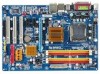
GA-P31-DS3/DS3L/S3L Motherboard Layout KB_MS COAXIAL OPTICAL ATX_12V LGA775 CPU_FAN COMA LPT PWR_FAN GA-P31-DS3/DS3L/S3L USB USB LAN F_AUDIO Intel® P31 AUDIO SYS_FAN1 DDRII1 PCIE_3 ATX CD_IN RTL8111B PCIE_16 DDRII2 DDRII3 DDRII4 PCIE_1 CLR_CMOS SPDIF_O CODEC PCIE_2 PCI1 SPDIF_I PCI2 IT8718 PCI3 CI FDD Intel® ICH7 BAT SATAII0 SATAII2 SYS_FAN2 BIOS SATAII1 SATAII3 IDE1 PWR_LED F_PANEL F_USB1 F_USB2 "*" Only the GA-P31-DS3/DS3L adopts All-Solid Capacitor design. - 7 -
GA-P31-DS3/DS3L/S3L Motherboard Layout KB_MS COAXIAL OPTICAL ATX_12V LGA775 CPU_FAN COMA LPT PWR_FAN GA-P31-DS3/DS3L/S3L USB USB LAN F_AUDIO Intel® P31 AUDIO SYS_FAN1 DDRII1 PCIE_3 ATX CD_IN RTL8111B PCIE_16 DDRII2 DDRII3 DDRII4 PCIE_1 CLR_CMOS SPDIF_O CODEC PCIE_2 PCI1 SPDIF_I PCI2 IT8718 PCI3 CI FDD Intel® ICH7 BAT SATAII0 SATAII2 SYS_FAN2 BIOS SATAII1 SATAII3 IDE1 PWR_LED F_PANEL F_USB1 F_USB2 "*" Only the GA-P31-DS3/DS3L adopts All-Solid Capacitor design. - 7 -
Manual
Page 8
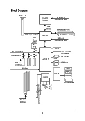
Block Diagram PCIe CLK (100 MHz) LGA775 Processor CPU CLK+/(333/266/200 MHz) PCI Express Bus PCI Express x16 LAN RJ45 RTL 8111B x1 3 PCI Express x1 x 1 x1 x1 PCIe CLK (100 MHz) PCI Bus Host Interface DDR2 800/667 MHz Intel® P31 Dual Channel Memory MCH CLK (333/266/200 MHz) Intel® ICH7 CODEC BIOS ATA-100/66/33 IDE Channel 4 SATA 3Gb/s 8 USB Ports IT8718 Floppy LPT Port COM Port PS/2 KB/Mouse Surround Speaker Out Center/Subwoofer Speaker Out Side Speaker Out MIC Line-Out Line-In SPDIF In SPDIF Out 3 PCI PCI CLK (33 MHz) - 8 -
Block Diagram PCIe CLK (100 MHz) LGA775 Processor CPU CLK+/(333/266/200 MHz) PCI Express Bus PCI Express x16 LAN RJ45 RTL 8111B x1 3 PCI Express x1 x 1 x1 x1 PCIe CLK (100 MHz) PCI Bus Host Interface DDR2 800/667 MHz Intel® P31 Dual Channel Memory MCH CLK (333/266/200 MHz) Intel® ICH7 CODEC BIOS ATA-100/66/33 IDE Channel 4 SATA 3Gb/s 8 USB Ports IT8718 Floppy LPT Port COM Port PS/2 KB/Mouse Surround Speaker Out Center/Subwoofer Speaker Out Side Speaker Out MIC Line-Out Line-In SPDIF In SPDIF Out 3 PCI PCI CLK (33 MHz) - 8 -

Manual
Page 10
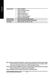
...Intel® Pentium® 4 processor/ Intel® Celeron® processor in the LGA 775 package (Go to GIGABYTE's website for the latest CPU support list.) Š Support for Intel® Hyper-Threading Technology Š L2 cache... Š Dual channel memory architecture Š Support for DDR2 800/667 MHz memory modules (Note 2) (Go to GIGABYTE's website for the latest memory support list.) Š Realtek ALC888 codec Š High Definition Audio Š 2/4/5.1/7.1-channel ...the USB brackets connected to the internal USB headers) "*" Only the GA-P31-DS3/DS3L adopts All-Solid Capacitor design.
...Intel® Pentium® 4 processor/ Intel® Celeron® processor in the LGA 775 package (Go to GIGABYTE's website for the latest CPU support list.) Š Support for Intel® Hyper-Threading Technology Š L2 cache... Š Dual channel memory architecture Š Support for DDR2 800/667 MHz memory modules (Note 2) (Go to GIGABYTE's website for the latest memory support list.) Š Realtek ALC888 codec Š High Definition Audio Š 2/4/5.1/7.1-channel ...the USB brackets connected to the internal USB headers) "*" Only the GA-P31-DS3/DS3L adopts All-Solid Capacitor design.
Manual
Page 12
... from the original frequency. (Please refer to to Page 16 for system usage and therefore the actual memory size is less than the stated amount. GA-P31-DS3/DS3L/S3L Motherboard - 12 -
... from the original frequency. (Please refer to to Page 16 for system usage and therefore the actual memory size is less than the stated amount. GA-P31-DS3/DS3L/S3L Motherboard - 12 -

Manual
Page 14
... off the computer and unplug the power cord from the power outlet to prevent damage to correctly install the CPU into the motherboard CPU socket. GA-P31-DS3/DS3L/S3L Motherboard - 14 - Follow the steps below to the CPU. CPU Socket Lever Step 1: Completely raise the CPU socket lever. Step 4: Hold the CPU...
... off the computer and unplug the power cord from the power outlet to prevent damage to correctly install the CPU into the motherboard CPU socket. GA-P31-DS3/DS3L/S3L Motherboard - 14 - Follow the steps below to the CPU. CPU Socket Lever Step 1: Completely raise the CPU socket lever. Step 4: Hold the CPU...

Manual
Page 16
... installing the memory in Dual Channel mode. 1. DS/SS - - rations below will double the original memory bandwidth. GA-P31-DS3/DS3L/S3L Motherboard - 16 - SS SS - - It is installed, the BIOS will automatically detect the specifications and capacity... of the memory. A memory module can be installed in only one DDR2 memory module is recommended that memory of the same capacity, brand, speed, and chips be used and installed according to GIGABYTE...
... installing the memory in Dual Channel mode. 1. DS/SS - - rations below will double the original memory bandwidth. GA-P31-DS3/DS3L/S3L Motherboard - 16 - SS SS - - It is installed, the BIOS will automatically detect the specifications and capacity... of the memory. A memory module can be installed in only one DDR2 memory module is recommended that memory of the same capacity, brand, speed, and chips be used and installed according to GIGABYTE...

Manual
Page 18
... you begin to install an expansion card: • Make sure the motherboard supports the expansion card. Make sure the metal contacts on your operating system. GA-P31-DS3/DS3L/S3L Motherboard - 18 - Locate an expansion slot that came with the slot, and press down on the card until it is locked by the...
... you begin to install an expansion card: • Make sure the motherboard supports the expansion card. Make sure the metal contacts on your operating system. GA-P31-DS3/DS3L/S3L Motherboard - 18 - Locate an expansion slot that came with the slot, and press down on the card until it is locked by the...

Manual
Page 20
... jack to connect rear speakers in jack ( ). Mic In Jack (Pink) The default Mic in jack. Refer to the default Mic in a 4/5.1/7.1-channel audio configuration. GA-P31-DS3/DS3L/S3L Motherboard - 20 -
... jack to connect rear speakers in jack ( ). Mic In Jack (Pink) The default Mic in jack. Refer to the default Mic in a 4/5.1/7.1-channel audio configuration. GA-P31-DS3/DS3L/S3L Motherboard - 20 -

Manual
Page 22
... 3.3V -12V GND PS_ON(soft On/Off) GND GND GND -5V +5V +5V +5V (Only for 2x12-pinATX) GND (Only for 2x12-pin ATX) GA-P31-DS3/DS3L/S3L Motherboard - 22 - If the 12V power connector is not connected, the computer will not start. • To meet expansion requirements, it is turned off...
... 3.3V -12V GND PS_ON(soft On/Off) GND GND GND -5V +5V +5V +5V (Only for 2x12-pinATX) GND (Only for 2x12-pin ATX) GA-P31-DS3/DS3L/S3L Motherboard - 22 - If the 12V power connector is not connected, the computer will not start. • To meet expansion requirements, it is turned off...

Manual
Page 24
... 3Gb/s standard and are compatible with SATA 1.5Gb/s standard. SATAII0 SATAII2 7 17 1 1 71 7 SATAII1 SATAII3 Pin No. 1 2 3 4 5 6 7 Definition GND TXP TXN GND RXN RXP GND GA-P31-DS3/DS3L/S3L Motherboard - 24 - Before attaching the IDE cable, locate the foolproof groove on the connector.
... 3Gb/s standard and are compatible with SATA 1.5Gb/s standard. SATAII0 SATAII2 7 17 1 1 71 7 SATAII1 SATAII3 Pin No. 1 2 3 4 5 6 7 Definition GND TXP TXN GND RXN RXP GND GA-P31-DS3/DS3L/S3L Motherboard - 24 - Before attaching the IDE cable, locate the foolproof groove on the connector.
Manual
Page 26
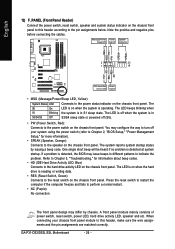
... 2, "BIOS Setup," "Power Management Setup," for information about beep codes. • HD (IDE Hard Drive Activity LED, Blue) Connects to the pin assignments below. GA-P31-DS3/DS3L/S3L Motherboard - 26 - The LED keeps blinking when S1 Blinking the system is detected at system startup. The S0 On LED is operating. One single...
... 2, "BIOS Setup," "Power Management Setup," for information about beep codes. • HD (IDE Hard Drive Activity LED, Blue) Connects to the pin assignments below. GA-P31-DS3/DS3L/S3L Motherboard - 26 - The LED keeps blinking when S1 Blinking the system is detected at system startup. The S0 On LED is operating. One single...

Manual
Page 28
... audio cable, carefully read the manual for your computer and unplug the power cord from the power outlet to prevent damage to the USB bracket. GA-P31-DS3/DS3L/S3L Motherboard - 28 - For purchasing the optional USB bracket, please contact the local dealer. Definition 2 10 1 9 1 Power (5V) 2 Power (5V) 3 USB DX- 4 USB DY...
... audio cable, carefully read the manual for your computer and unplug the power cord from the power outlet to prevent damage to the USB bracket. GA-P31-DS3/DS3L/S3L Motherboard - 28 - For purchasing the optional USB bracket, please contact the local dealer. Definition 2 10 1 9 1 Power (5V) 2 Power (5V) 3 USB DX- 4 USB DY...
Manual
Page 30
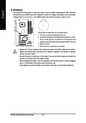
... may not be handled in accordance with an equivalent one minute. (Or use a metal object like a screwdriver to replace the battery by removing the battery: 1. GA-P31-DS3/DS3L/S3L Motherboard - 30 - English 19) BAT(Battery) The battery provides power to keep the values (such as BIOS configurations, date, and time information) in...
... may not be handled in accordance with an equivalent one minute. (Or use a metal object like a screwdriver to replace the battery by removing the battery: 1. GA-P31-DS3/DS3L/S3L Motherboard - 30 - English 19) BAT(Battery) The battery provides power to keep the values (such as BIOS configurations, date, and time information) in...

Manual
Page 32
...Full Screen LOGO Show item on BIOS Setup settings. Motherboard Model BIOS Version Intel P31 BIOS for one time only. To show the BIOS POST screen. Note: The setting in Boot Menu. GA-P31-DS3/DS3L/S3L Motherboard - 32 - After system restart, the device boot order will ...directly boot from the device configured in Boot Menu is effective for P31-DS3 E14 . . . . : BIOS Setup/Q-Flash : XpressRecovery2 : Boot ...
...Full Screen LOGO Show item on BIOS Setup settings. Motherboard Model BIOS Version Intel P31 BIOS for one time only. To show the BIOS POST screen. Note: The setting in Boot Menu. GA-P31-DS3/DS3L/S3L Motherboard - 32 - After system restart, the device boot order will ...directly boot from the device configured in Boot Menu is effective for P31-DS3 E14 . . . . : BIOS Setup/Q-Flash : XpressRecovery2 : Boot ...

Manual
Page 33
Use arrow keys to move among the items and press to accept or enter a sub-menu. (Sample BIOS Version: GA-P31-DS3 E14) CMOS Setup Utility-Copyright (C) 1984-2007 Award Software ` Standard CMOS Features ` Advanced BIOS Features ` Integrated Peripherals ` Power Management Setup ` PnP/PCI Configurations ` PC ...
Use arrow keys to move among the items and press to accept or enter a sub-menu. (Sample BIOS Version: GA-P31-DS3 E14) CMOS Setup Utility-Copyright (C) 1984-2007 Award Software ` Standard CMOS Features ` Advanced BIOS Features ` Integrated Peripherals ` Power Management Setup ` PnP/PCI Configurations ` PC ...

Manual
Page 34
... to configure all the changes made in the BIOS Setup program to the CMOS and exit BIOS Setup. (Pressing can also carry out this task.) GA-P31-DS3/DS3L/S3L Motherboard - 34 - Pressing to the confirmation message will exit BIOS Setup. (Pressing can also carry out this task.) „ Exit Without Saving Abandon...
... to configure all the changes made in the BIOS Setup program to the CMOS and exit BIOS Setup. (Pressing can also carry out this task.) GA-P31-DS3/DS3L/S3L Motherboard - 34 - Pressing to the confirmation message will exit BIOS Setup. (Pressing can also carry out this task.) „ Exit Without Saving Abandon...
