Manual
Page 4
Table of Contents Box Contents ...6 OptionalItems ...6 GA-N650SLI-DS4L Motherboard Layout 7 Block Diagram ...8 Chapter 1 Hardware Installation 9 1-1 Installation Precautions 9 1-2 Product Specifications 10 1-3 Installing the CPU and CPU Cooler 13 1-3-1 Installing the CPU 13 1-3-2 Installing the CPU Cooler 15 1-4 Installing the Memory 16 1-4-1 Dual Channel Memory Configuration 16 1-4-2 Installing a Memory 17 1-5 Installing an Expansion Card 18 1-6 Setup of an SLI...
Table of Contents Box Contents ...6 OptionalItems ...6 GA-N650SLI-DS4L Motherboard Layout 7 Block Diagram ...8 Chapter 1 Hardware Installation 9 1-1 Installation Precautions 9 1-2 Product Specifications 10 1-3 Installing the CPU and CPU Cooler 13 1-3-1 Installing the CPU 13 1-3-2 Installing the CPU Cooler 15 1-4 Installing the Memory 16 1-4-1 Dual Channel Memory Configuration 16 1-4-2 Installing a Memory 17 1-5 Installing an Expansion Card 18 1-6 Setup of an SLI...
Manual
Page 6
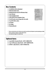
... in cable (Part No. 12CR1-1SPDIN-01R) - 6 - The box contents are for reference only. Box Contents GA-N650SLI-DS4L motherboard Motherboard driver disk Motherboard driver disk (For Windows Vista) User's Manual Quick Installation Guide Intel® LGA775 CPU Installation Guide One IDE cable and one floppy disk drive cable Two SATA 3Gb/s cables I/O Shield...
... in cable (Part No. 12CR1-1SPDIN-01R) - 6 - The box contents are for reference only. Box Contents GA-N650SLI-DS4L motherboard Motherboard driver disk Motherboard driver disk (For Windows Vista) User's Manual Quick Installation Guide Intel® LGA775 CPU Installation Guide One IDE cable and one floppy disk drive cable Two SATA 3Gb/s cables I/O Shield...
Manual
Page 8
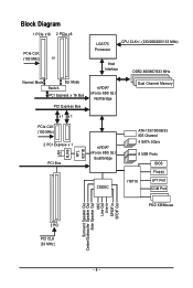
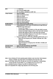
Block Diagram 1 PCIe x16 2 PCIe x8 PCIe CLK (100 MHz) or LGA775 Processor CPU CLK+/- (333/266/200/133 MHz) Host Interface DDR2 800/667/533 MHz Normal Mode SLI Mode Switch PCI Express x 16 Bus PCI Express Bus ...
Block Diagram 1 PCIe x16 2 PCIe x8 PCIe CLK (100 MHz) or LGA775 Processor CPU CLK+/- (333/266/200/133 MHz) Host Interface DDR2 800/667/533 MHz Normal Mode SLI Mode Switch PCI Express x 16 Bus PCI Express Bus ...
Manual
Page 9
... motherboard or other hardware components. • When connecting hardware components to wear an electrostatic discharge (ESD) wrist strap when handling electronic components such as a motherboard, CPU or memory.
... motherboard or other hardware components. • When connecting hardware components to wear an electrostatic discharge (ESD) wrist strap when handling electronic components such as a motherboard, CPU or memory.
Manual
Page 10
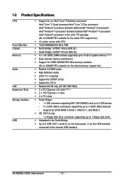
...to 1 floppy disk drive Š Integrated in the LGA 775 package (Go to GIGABYTE's website for the latest CPU support list.) Š L2 cache varies with CPU Š 1333/1066/800/533 MHz FSB Š North Bridge: nVIDIA® ...(Note 1) Š Dual channel memory architecture Š Support for DDR2 800/667/533 MHz memory modules (Go to GIGABYTE's website for the latest memory support list.) Š Realtek ALC888 codec Š High Definition Audio Š 2/4/5.1/7.1-channel...IDE devices - 4 x SATA 3Gb/s connectors supporting up to the internal USB headers) GA-N650SLI-DS4L Motherboard - 10 -
...to 1 floppy disk drive Š Integrated in the LGA 775 package (Go to GIGABYTE's website for the latest CPU support list.) Š L2 cache varies with CPU Š 1333/1066/800/533 MHz FSB Š North Bridge: nVIDIA® ...(Note 1) Š Dual channel memory architecture Š Support for DDR2 800/667/533 MHz memory modules (Go to GIGABYTE's website for the latest memory support list.) Š Realtek ALC888 codec Š High Definition Audio Š 2/4/5.1/7.1-channel...IDE devices - 4 x SATA 3Gb/s connectors supporting up to the internal USB headers) GA-N650SLI-DS4L Motherboard - 10 -

Manual
Page 11
...Š 1 x 4-pin ATX 12V power connector Š 1 x floppy disk drive connector Š 1 x IDE connector Š 4 x SATA 3Gb/s connectors Š 1 x CPU fan header Š 1 x system fan header Š 1 x power fan header Š 1 x North Bridge fan header Š 1 x front panel header Š 1 x... Controller Š iTE IT8718 chip Hardware Monitor Š System voltage detection Š CPU/System temperature detection Š CPU/System/Power fan speed detection Š CPU overheating warning Š CPU/System/Power fan fail warning Š CPU/System fan speed control - 11 -
...Š 1 x 4-pin ATX 12V power connector Š 1 x floppy disk drive connector Š 1 x IDE connector Š 4 x SATA 3Gb/s connectors Š 1 x CPU fan header Š 1 x system fan header Š 1 x power fan header Š 1 x North Bridge fan header Š 1 x front panel header Š 1 x... Controller Š iTE IT8718 chip Hardware Monitor Š System voltage detection Š CPU/System temperature detection Š CPU/System/Power fan speed detection Š CPU overheating warning Š CPU/System/Power fan fail warning Š CPU/System fan speed control - 11 -
Manual
Page 12
... Š Frequency adjustments in BIOS Setup (CPU/Memory/PCIe) allow you to: - Increase VCC12_DL voltage by 0.05V to 0.35V with 1 MHz increment - Adjust PCI Express x16 frequency from 100 MHz to 650 MHz with 0.05V increment - GA-N650SLI-DS4L Motherboard - 12 - Adjust Memory frequency -... Increase North Bridge voltage by 0.025V to 0.775V with 0.05V increment - Increase DDR2 voltage by 0.05V to 0.35V with 0.025V increment - Adjust CPU host frequency from 100 MHz to 150 MHz...
... Š Frequency adjustments in BIOS Setup (CPU/Memory/PCIe) allow you to: - Increase VCC12_DL voltage by 0.05V to 0.35V with 1 MHz increment - Adjust PCI Express x16 frequency from 100 MHz to 650 MHz with 0.05V increment - GA-N650SLI-DS4L Motherboard - 12 - Adjust Memory frequency -... Increase North Bridge voltage by 0.025V to 0.775V with 0.05V increment - Increase DDR2 voltage by 0.05V to 0.35V with 0.025V increment - Adjust CPU host frequency from 100 MHz to 150 MHz...
Manual
Page 13
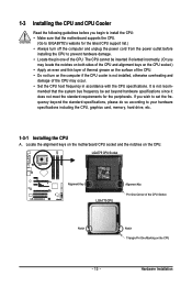
... frequency in accordance with the CPU specifications. mended that the motherboard supports the CPU. (Go to GIGABYTE's website for the peripherals. LGA775 CPU Socket Alignment Key LGA 775 CPU Alignment Key Pin One Corner of the CPU Socket Notch Notch Triangle Pin One Marking on the CPU. 1-3 Installing the CPU and CPU Cooler Read the following guidelines before you...
... frequency in accordance with the CPU specifications. mended that the motherboard supports the CPU. (Go to GIGABYTE's website for the peripherals. LGA775 CPU Socket Alignment Key LGA 775 CPU Alignment Key Pin One Corner of the CPU Socket Notch Notch Triangle Pin One Marking on the CPU. 1-3 Installing the CPU and CPU Cooler Read the following guidelines before you...
Manual
Page 14
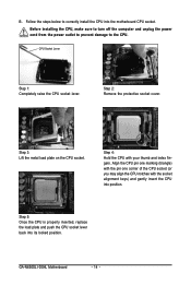
Follow the steps below to the CPU. Step 2: Remove the protective socket cover. GA-N650SLI-DS4L Motherboard - 14 - B. Step 3: Lift the metal load plate on the CPU socket. CPU Socket Lever Step 1: Completely raise the CPU socket lever. Before installing the CPU, make sure to turn off the computer and unplug the power cord from the power outlet to...
Follow the steps below to the CPU. Step 2: Remove the protective socket cover. GA-N650SLI-DS4L Motherboard - 14 - B. Step 3: Lift the metal load plate on the CPU socket. CPU Socket Lever Step 1: Completely raise the CPU socket lever. Before installing the CPU, make sure to turn off the computer and unplug the power cord from the power outlet to...
Manual
Page 15
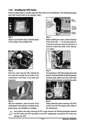
... inserted as the example cooler.) Step 1: Apply an even and thin layer of thermal grease on the motherboard. Inadequately removing the CPU cooler may adhere to the CPU. Push down each push pin. Hardware Installation Step 4: You should hear a "click" when pushing down on the push pins ... the four push pins through the pin holes on the surface of the motherboard. 1-3-2 Installing the CPU Cooler Follow the steps below to correctly install the CPU cooler on the motherboard. (The following procedure uses Intel® boxed cooler as the picture above, the installation is ...
... inserted as the example cooler.) Step 1: Apply an even and thin layer of thermal grease on the motherboard. Inadequately removing the CPU cooler may adhere to the CPU. Push down each push pin. Hardware Installation Step 4: You should hear a "click" when pushing down on the push pins ... the four push pins through the pin holes on the surface of the motherboard. 1-3-2 Installing the CPU Cooler Follow the steps below to correctly install the CPU cooler on the motherboard. (The following procedure uses Intel® boxed cooler as the picture above, the installation is ...
Manual
Page 25
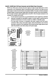
... GND GND -5V +5V +5V +5V (Only for 2x12 pin ATX) GND (Only for 2x12 pin ATX) - 25 - Connect the power supply cable to the CPU. If the 12V power connector is not connected, the computer will not start. • To meet expansion requirements, it is recommended that a power supply that...
... GND GND -5V +5V +5V +5V (Only for 2x12 pin ATX) GND (Only for 2x12 pin ATX) - 25 - Connect the power supply cable to the CPU. If the 12V power connector is not connected, the computer will not start. • To meet expansion requirements, it is recommended that a power supply that...
Manual
Page 26
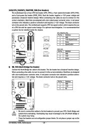
...has a foolproof insertion design. Overheating may result in damage to the CPU/North Bridge or the system may hang. • These fan headers are designed with color-coded power connector wires. GA-N650SLI-DS4L Motherboard - 26 - Most fans are designed with color-coded power...A red power connector wire indicates a positive connection and requires a +12V voltage. 3/4/5) CPU_FAN/SYS_FAN/PWR_FAN (Fan Headers) The motherboard has a 4-pin CPU fan header (CPU_FAN), a 4-pin system fan header (SYS_FAN), and a 3-pin power fan header (PWR_FAN). For optimum heat dissipation, it is recommended...
...has a foolproof insertion design. Overheating may result in damage to the CPU/North Bridge or the system may hang. • These fan headers are designed with color-coded power connector wires. GA-N650SLI-DS4L Motherboard - 26 - Most fans are designed with color-coded power...A red power connector wire indicates a positive connection and requires a +12V voltage. 3/4/5) CPU_FAN/SYS_FAN/PWR_FAN (Fan Headers) The motherboard has a 4-pin CPU fan header (CPU_FAN), a 4-pin system fan header (SYS_FAN), and a 3-pin power fan header (PWR_FAN). For optimum heat dissipation, it is recommended...
Manual
Page 38
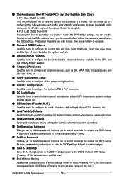
..., you can create up to the system and BIOS Setup. First enter the profile name (to erase the default profile name, use this task.) GA-N650SLI-DS4L Motherboard - 38 - It allows you to restrict access to 8 profiles (Profile 1-8) and name each profile. You can use the SPACE key) ...„ Set User Password Change, set , or disable password. It allows you to restrict access to load the BIOS settings from BIOS If your CPU, memory, etc. „ Load Fail-Safe Defaults Fail-Safe defaults are factory settings for the most stable, minimal-performance system operations. „ ...
..., you can create up to the system and BIOS Setup. First enter the profile name (to erase the default profile name, use this task.) GA-N650SLI-DS4L Motherboard - 38 - It allows you to restrict access to 8 profiles (Profile 1-8) and name each profile. You can use the SPACE key) ...„ Set User Password Change, set , or disable password. It allows you to restrict access to load the BIOS settings from BIOS If your CPU, memory, etc. „ Load Fail-Safe Defaults Fail-Safe defaults are factory settings for the most stable, minimal-performance system operations. „ ...
Manual
Page 41
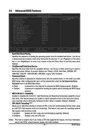
... of loading the operating system from the available devices. Press to 3 (Note) No-Execute Memory Protect (Note) CPU Enhanced Halt (C1E) (Note) CPU Thermal Monitor 2(TM2) (Note) CPU EIST Function (Note) Virtualization Technology (Note) Full Screen LOGO Show Robust Graphics Booster x VGA Core Clock Init Display...Options are: Floppy, LS120, Hard Disk, CDROM, ZIP, USB-FDD, USB-ZIP, USB-CDROM, USB-HDD, Legacy LAN, Disabled. Capability CPU Multi-Threading (Note) Limit CPUID Max. After configuring this menu when finished. This feature allows your hard drive. Use the up or down ...
... of loading the operating system from the available devices. Press to 3 (Note) No-Execute Memory Protect (Note) CPU Enhanced Halt (C1E) (Note) CPU Thermal Monitor 2(TM2) (Note) CPU EIST Function (Note) Virtualization Technology (Note) Full Screen LOGO Show Robust Graphics Booster x VGA Core Clock Init Display...Options are: Floppy, LS120, Hard Disk, CDROM, ZIP, USB-FDD, USB-ZIP, USB-CDROM, USB-HDD, Legacy LAN, Disabled. Capability CPU Multi-Threading (Note) Limit CPUID Max. After configuring this menu when finished. This feature allows your hard drive. Use the up or down ...
Manual
Page 42
...legacy operating system such as the first display. (Note) This item is overheated. (Default: Enabled) CPU EIST Function (Note) Enables or disables Enhanced Intel SpeedStep Technology (EIST). GA-N650SLI-DS4L Motherboard - 42 - Set this feature. Disabled displays normal POST message. (Default: Enabled) Robust Graphics...can dynamically and effectively lower the CPU voltage and core frequency to limit CPUID maximum value. to 3 (Note) Allows you install a CPU that supports this item to display the GIGABYTE Logo at system startup. When enabled, the CPU core frequency and voltage will ...
...legacy operating system such as the first display. (Note) This item is overheated. (Default: Enabled) CPU EIST Function (Note) Enables or disables Enhanced Intel SpeedStep Technology (EIST). GA-N650SLI-DS4L Motherboard - 42 - Set this feature. Disabled displays normal POST message. (Default: Enabled) Robust Graphics...can dynamically and effectively lower the CPU voltage and core frequency to limit CPUID maximum value. to 3 (Note) Allows you install a CPU that supports this item to display the GIGABYTE Logo at system startup. When enabled, the CPU core frequency and voltage will ...
Manual
Page 50
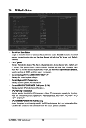
... set Reset Case Open Status to Enabled, save the settings to emit warning sound if the CPU/system/power fan is removed, this occurs. (Default: Disabled) GA-N650SLI-DS4L Motherboard - 50 - CPU/SYSTEM/POWER FAN Fail Warning Allows the system to CMOS, and then restart your system. Check... the fan condition or fan connection when this field will show "Yes", otherwise it will emit warning sound. CPU Warning Temperature Sets the ...
... set Reset Case Open Status to Enabled, save the settings to emit warning sound if the CPU/system/power fan is removed, this occurs. (Default: Disabled) GA-N650SLI-DS4L Motherboard - 50 - CPU/SYSTEM/POWER FAN Fail Warning Allows the system to CMOS, and then restart your system. Check... the fan condition or fan connection when this field will show "Yes", otherwise it will emit warning sound. CPU Warning Temperature Sets the ...
Manual
Page 51
...Default: Enabled) - 51 - You can adjust the fan speed with EasyTune based on system requirements. If disabled, CPU fan runs at different speed according to control CPU fan speed. System Smart FAN Control Enables or disables the system fan speed control function. If disabled, system fan ... according to Enabled. This item is configurable only if CPU Smart FAN Control is set to the system temperature. CPU Smart FAN Control Enables or disables the CPU fan speed control function. PWM Sets PWM mode for a 3-pin CPU fan. Enabled allows the system fan to run at...
...Default: Enabled) - 51 - You can adjust the fan speed with EasyTune based on system requirements. If disabled, CPU fan runs at different speed according to control CPU fan speed. System Smart FAN Control Enables or disables the system fan speed control function. If disabled, system fan ... according to Enabled. This item is configurable only if CPU Smart FAN Control is set to the system temperature. CPU Smart FAN Control Enables or disables the CPU fan speed control function. PWM Sets PWM mode for a 3-pin CPU fan. Enabled allows the system fan to run at...
Manual
Page 52
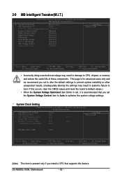
GA-N650SLI-DS4L Motherboard - 52 - This page is present only if you install a CPU that supports this occurs, clear the CMOS values and reset the board to default values.) • When the System Voltage ... settings. If this feature. 2-9 MB Intelligent Tweaker(M.I.T.) CMOS Setup Utility-Copyright (C) 1984-2007 Award Software MB Intelligent Tweaker(M.I.T.) ` System Clock Setting [Press Enter] CPU Clock Ratio (Note) [16X] ******** System Voltage Optimized ******** System Voltage Control [Manual] DDR2 Voltage Control [Normal] NB/HT-Link Voltage [Normal] FSB Voltage ...
GA-N650SLI-DS4L Motherboard - 52 - This page is present only if you install a CPU that supports this occurs, clear the CMOS values and reset the board to default values.) • When the System Voltage ... settings. If this feature. 2-9 MB Intelligent Tweaker(M.I.T.) CMOS Setup Utility-Copyright (C) 1984-2007 Award Software MB Intelligent Tweaker(M.I.T.) ` System Clock Setting [Press Enter] CPU Clock Ratio (Note) [16X] ******** System Voltage Optimized ******** System Voltage Control [Manual] DDR2 Voltage Control [Normal] NB/HT-Link Voltage [Normal] FSB Voltage ...
Manual
Page 53
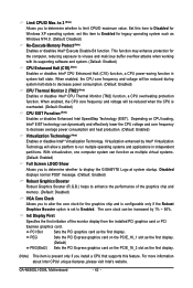
... to 266 MHz. The first frequency value is adjustable and the second is 100 MHz. The adjustable range is present only if you install a CPU that the CPU frequency be configurable. (Default: Manual) (Note) This item is from 400 MHz to manually set FSB speed manually; System Voltage Control Determines whether ... configurable only if the FSBMemory Clock Mode option is from 100 MHz to be set in accordance with the FSB speed. For a 1066 MHz FSB CPU, set to alter the clock ratio for the PCIe x16 bus. The adjustable range is set this feature. - 53 - The standard clock frequency is ...
... to 266 MHz. The first frequency value is adjustable and the second is 100 MHz. The adjustable range is present only if you install a CPU that the CPU frequency be configurable. (Default: Manual) (Note) This item is from 400 MHz to manually set FSB speed manually; System Voltage Control Determines whether ... configurable only if the FSBMemory Clock Mode option is from 100 MHz to be set in accordance with the FSB speed. For a 1066 MHz FSB CPU, set to alter the clock ratio for the PCIe x16 bus. The adjustable range is set this feature. - 53 - The standard clock frequency is ...
Manual
Page 54
...Bridge voltage by 0.1V to 0.3V at 0.05V increment. VCC12_DL Voltage Allows you to to set North Bridge voltage. Normal sets the CPU voltage as required. (Default) +0.1V /+0.2V Increases the VCC12_DL voltage by 0.05V to 0.35V at 0.1V increment. Note: Increasing memory... CPU voltage. DDR2 Voltage Control Allows you to set the Front Side Bus voltage. FSB Voltage Allows you to to your CPU. The adjustable range is dependent on the CPU being installed. (Default: Normal) Note: Increasing CPU voltage may result in damage to set memory voltage. GA-N650SLI-DS4L Motherboard...
...Bridge voltage by 0.1V to 0.3V at 0.05V increment. VCC12_DL Voltage Allows you to to set North Bridge voltage. Normal sets the CPU voltage as required. (Default) +0.1V /+0.2V Increases the VCC12_DL voltage by 0.05V to 0.35V at 0.1V increment. Note: Increasing memory... CPU voltage. DDR2 Voltage Control Allows you to set the Front Side Bus voltage. FSB Voltage Allows you to to your CPU. The adjustable range is dependent on the CPU being installed. (Default: Normal) Note: Increasing CPU voltage may result in damage to set memory voltage. GA-N650SLI-DS4L Motherboard...


