Manual
Page 3
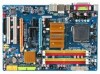
... Installation Guide included with the product. „ For detailed product information, carefully read or download the information on/from the Support\Motherboard\Technology Guide page on your motherboard revision before updating motherboard BIOS, drivers, or when looking for technical information. Example: is... on our website. by GIGA-BYTE TECHNOLOGY CO., LTD as the exclu- For example, "REV: 1.0" means the revision of GIGABYTE branded motherboards. Check your motherboard looks like this manual may be made by any means without prior notice. Changes to their respective ...
... Installation Guide included with the product. „ For detailed product information, carefully read or download the information on/from the Support\Motherboard\Technology Guide page on your motherboard revision before updating motherboard BIOS, drivers, or when looking for technical information. Example: is... on our website. by GIGA-BYTE TECHNOLOGY CO., LTD as the exclu- For example, "REV: 1.0" means the revision of GIGABYTE branded motherboards. Check your motherboard looks like this manual may be made by any means without prior notice. Changes to their respective ...
Manual
Page 10
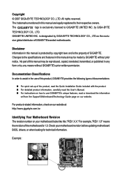
.../Intel® Pentium® 4 processor/ Intel® Celeron® processor in the LGA 775 package (Go to GIGABYTE's website for the latest CPU support list.) Š L2 cache varies with CPU Š 1333/1066/800/533 MHz FSB Š North Bridge: ...GIGABYTE's website for the latest memory support list.) Š Realtek ALC888 codec Š High Definition Audio Š 2/4/5.1/7.1-channel Š Support for S/PDIF In/Out Š Support for SATA RAID 0, RAID 1, RAID 0+1, and RAID 5 Š iTE IT8718 chip: - 1 x floppy disk drive connector supporting up to the internal USB headers) GA-N650SLI-DS4L...
.../Intel® Pentium® 4 processor/ Intel® Celeron® processor in the LGA 775 package (Go to GIGABYTE's website for the latest CPU support list.) Š L2 cache varies with CPU Š 1333/1066/800/533 MHz FSB Š North Bridge: ...GIGABYTE's website for the latest memory support list.) Š Realtek ALC888 codec Š High Definition Audio Š 2/4/5.1/7.1-channel Š Support for S/PDIF In/Out Š Support for SATA RAID 0, RAID 1, RAID 0+1, and RAID 5 Š iTE IT8718 chip: - 1 x floppy disk drive connector supporting up to the internal USB headers) GA-N650SLI-DS4L...
Manual
Page 12
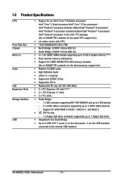
... - Adjust CPU host frequency from 100 MHz to 150 MHz with 0.025V increment - GA-N650SLI-DS4L Motherboard - 12 - Increase North Bridge voltage by 0.025V to 0.775V with 1 MHz increment Š Support for Microsoft® Windows® Vista/XP/2000 Š ATX Form Factor; 30....PnP 1.0a, DMI 2.0, SM BIOS 2.3, ACPI 1.0b Š Support for @BIOS Š Support for Download Center Š Support for Q-Flash Š Support for EasyTune (Note 3) Š Support for Xpress Install Š Support for Xpress Recovery2 Š Support for Virtual Dual BIOS Š Norton Internet Security (OEM version)...
... - Adjust CPU host frequency from 100 MHz to 150 MHz with 0.025V increment - GA-N650SLI-DS4L Motherboard - 12 - Increase North Bridge voltage by 0.025V to 0.775V with 1 MHz increment Š Support for Microsoft® Windows® Vista/XP/2000 Š ATX Form Factor; 30....PnP 1.0a, DMI 2.0, SM BIOS 2.3, ACPI 1.0b Š Support for @BIOS Š Support for Download Center Š Support for Q-Flash Š Support for EasyTune (Note 3) Š Support for Xpress Install Š Support for Xpress Recovery2 Š Support for Virtual Dual BIOS Š Norton Internet Security (OEM version)...
Manual
Page 13
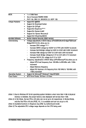
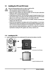
... installing the CPU to your hardware specifications including the CPU, graphics card, memory, hard drive, etc. 1-3-1 Installing the CPU A. mended that the motherboard supports the CPU. (Go to GIGABYTE's website for the peripherals. Hardware Installation LGA775 CPU Socket Alignment Key LGA 775 CPU Alignment Key Pin One Corner of the CPU. The...
... installing the CPU to your hardware specifications including the CPU, graphics card, memory, hard drive, etc. 1-3-1 Installing the CPU A. mended that the motherboard supports the CPU. (Go to GIGABYTE's website for the peripherals. Hardware Installation LGA775 CPU Socket Alignment Key LGA 775 CPU Alignment Key Pin One Corner of the CPU. The...
Manual
Page 16
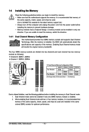
...are unable to insert the memory, switch the direction. 1-4-1 Dual Channel Memory Configuration This motherboard provides four DDR2 memory sockets and supports Dual Channel Technology. Four Modules DS/SS DS/SS DS/SS DDRII4 - Dual Channel mode cannot be enabled if only one... GIGABYTE's website for optimum performance. DS/SS DS/SS (SS=Single-Sided, DS=Double-Sided, "- -"=No Memory) DDRII1 DDRII2 DDRII3 DDRII4 Due to chipset limitation, read the following guidelines before installing the memory to prevent hardware damage. • Memory modules have a foolproof design. GA-N650SLI-DS4L ...
...are unable to insert the memory, switch the direction. 1-4-1 Dual Channel Memory Configuration This motherboard provides four DDR2 memory sockets and supports Dual Channel Technology. Four Modules DS/SS DS/SS DS/SS DDRII4 - Dual Channel mode cannot be enabled if only one... GIGABYTE's website for optimum performance. DS/SS DS/SS (SS=Single-Sided, DS=Double-Sided, "- -"=No Memory) DDRII1 DDRII2 DDRII3 DDRII4 Due to chipset limitation, read the following guidelines before installing the memory to prevent hardware damage. • Memory modules have a foolproof design. GA-N650SLI-DS4L ...
Manual
Page 18
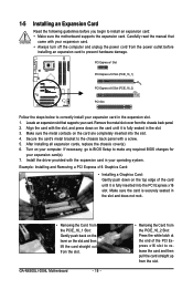
...and then lift the card straight out from the power outlet before you begin to install an expansion card: • Make sure the motherboard supports the expansion card. After installing all expansion cards, replace the chassis cover(s). 6. Turn on the top edge of the PCI Express x16 ... slot. Make sure the card is fully inserted into the slot. 4. Carefully read the manual that supports your computer. Install the driver provided with the slot, and press down on your card. GA-N650SLI-DS4L Motherboard - 18 - • Removing the Card from the PCIE_16_2 Slot: Press the white latch at...
...and then lift the card straight out from the power outlet before you begin to install an expansion card: • Make sure the motherboard supports the expansion card. After installing all expansion cards, replace the chassis cover(s). 6. Turn on the top edge of the PCI Express x16 ... slot. Make sure the card is fully inserted into the slot. 4. Carefully read the manual that supports your computer. Install the driver provided with the slot, and press down on your card. GA-N650SLI-DS4L Motherboard - 18 - • Removing the Card from the PCIE_16_2 Slot: Press the white latch at...
Manual
Page 19
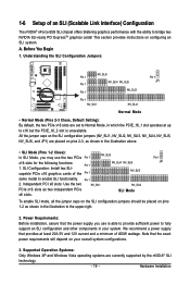
... of 400W wattage. Independent PCI x8 slots: Use the two NV_SLI1 NV_SLI2 PCIe x16 slots as shown in your overall system configurations. 3. Supported Operation Systems: Only Windows XP and Windows Vista operating systems are placed on pins 2-3, as shown in the illustration above. • SLI...is unavailable. This section provides instructions on the SLI configuration jumpers (NV_SLI1, NV_SLI2, NV_SLI3, NV_SLI4, NV_SLI5, NV_SLI6, and JP1) are currently supported by the nVIDIA® SLI technology. - 19 - SLI Mode Pin 1 JP1 To enable SLI mode, all the jumper caps on ...
... of 400W wattage. Independent PCI x8 slots: Use the two NV_SLI1 NV_SLI2 PCIe x16 slots as shown in your overall system configurations. 3. Supported Operation Systems: Only Windows XP and Windows Vista operating systems are placed on pins 2-3, as shown in the illustration above. • SLI...is unavailable. This section provides instructions on the SLI configuration jumpers (NV_SLI1, NV_SLI2, NV_SLI3, NV_SLI4, NV_SLI5, NV_SLI6, and JP1) are currently supported by the nVIDIA® SLI technology. - 19 - SLI Mode Pin 1 JP1 To enable SLI mode, all the jumper caps on ...
Manual
Page 22
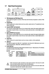
Parallel Port Use the parallel port to an external audio system that supports digital coaxial audio. Use this port for USB devices such as a printer, scanner and etc. Connection/ Speed LED Activity LED LAN Port ... LED: State Description Blinking Data transmission or receiving is occurring Off No data transmission or receiving is also called a printer port. GA-N650SLI-DS4L Motherboard - 22 - USB Port The USB port supports the USB 2.0/1.1 specification. Before using this feature, ensure that your audio system provides a coaxial digital audio in connector. Optical ...
Parallel Port Use the parallel port to an external audio system that supports digital coaxial audio. Use this port for USB devices such as a printer, scanner and etc. Connection/ Speed LED Activity LED LAN Port ... LED: State Description Blinking Data transmission or receiving is occurring Off No data transmission or receiving is also called a printer port. GA-N650SLI-DS4L Motherboard - 22 - USB Port The USB port supports the USB 2.0/1.1 specification. Before using this feature, ensure that your audio system provides a coaxial digital audio in connector. Optical ...
Manual
Page 26
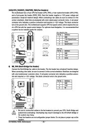
...North Bridge fan cable to prevent your CPU, North Bridge and system from overheating. The fan header has a foolproof insertion design. Pin No. GA-N650SLI-DS4L Motherboard - 26 - A red power connector wire indicates a positive connection and requires a +12V voltage. Overheating may hang. • These...pin system fan header (SYS_FAN), and a 3-pin power fan header (PWR_FAN). The black connector wire is the ground wire. The motherboard supports CPU fan speed control, which requires the use of a CPU fan with fan speed control design. When connecting a fan cable, be ...
...North Bridge fan cable to prevent your CPU, North Bridge and system from overheating. The fan header has a foolproof insertion design. Pin No. GA-N650SLI-DS4L Motherboard - 26 - A red power connector wire indicates a positive connection and requires a +12V voltage. Overheating may hang. • These...pin system fan header (SYS_FAN), and a 3-pin power fan header (PWR_FAN). The black connector wire is the ground wire. The motherboard supports CPU fan speed control, which requires the use of a CPU fan with fan speed control design. When connecting a fan cable, be ...

Manual
Page 27
... the IDE cable, locate the foolproof groove on the connector. The types of different color. 33 1 34 2 8) IDE1 (IDE Connector) The IDE connector supports up to the role of the connector and the floppy disk drive cable. If you wish to connect two IDE devices, remember to set the... IDE devices such as hard drives and optical drives. 7) FDD (Floppy Disk Drive Connector) This connector is typically designated by a stripe of floppy disk drives supported are: 360 KB, 720 KB, 1.2 MB, 1.44 MB, and 2.88 MB. Before connecting a floppy disk drive, be sure to connect a floppy disk drive...
... the IDE cable, locate the foolproof groove on the connector. The types of different color. 33 1 34 2 8) IDE1 (IDE Connector) The IDE connector supports up to the role of the connector and the floppy disk drive cable. If you wish to connect two IDE devices, remember to set the... IDE devices such as hard drives and optical drives. 7) FDD (Floppy Disk Drive Connector) This connector is typically designated by a stripe of floppy disk drives supported are: 360 KB, 720 KB, 1.2 MB, 1.44 MB, and 2.88 MB. Before connecting a floppy disk drive, be sure to connect a floppy disk drive...
Manual
Page 28
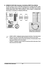
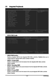
Each SATA connector supports a single SATA device. GA-N650SLI-DS4L Motherboard - 28 - If more than two hard drives are compatible with SATA 1.5Gb/s standard. 9) SATAII0/1/2/3 (SATA 3Gb/s Connectors, Controlled by nVIDIA® ... number of the SATA 3Gb/s cable to Chapter 5, "Configuring SATA Hard Drive(s)," for instructions on configuring a RAID array. The nVIDIA® nForce 650i SLI controller supports RAID 0, RAID 1, RAID 5 and RAID 0+1. SATAII1 7 1 SATAII3 7 1 7 1 SATAII0 7 1 SATAII2 Pin No. 1 2 3 4 5 6 7 Definition GND TXP TXN GND RXN RXP GND Please connect the...
Each SATA connector supports a single SATA device. GA-N650SLI-DS4L Motherboard - 28 - If more than two hard drives are compatible with SATA 1.5Gb/s standard. 9) SATAII0/1/2/3 (SATA 3Gb/s Connectors, Controlled by nVIDIA® ... number of the SATA 3Gb/s cable to Chapter 5, "Configuring SATA Hard Drive(s)," for instructions on configuring a RAID array. The nVIDIA® nForce 650i SLI controller supports RAID 0, RAID 1, RAID 5 and RAID 0+1. SATAII1 7 1 SATAII3 7 1 7 1 SATAII0 7 1 SATAII2 Pin No. 1 2 3 4 5 6 7 Definition GND TXP TXN GND RXN RXP GND Please connect the...

Manual
Page 31
... may connect your optical drive to this header. Definition 1 CD-L 2 GND 3 GND 1 4 CD-R - 31 - 13) F_AUDIO (Front Panel Audio Header) The front panel audio header supports Intel High Definition audio (HD) and AC'97 audio. Pin No. Definition Pin No. You may connect the audio cable that has separated connectors on... 4 NC 5 LINE2_R 5 Line Out (R) 6 FSENSE1 6 NC 7 FAUDIO_JD 7 NC 8 No Pin 8 No Pin 9 LINE2_L 9 Line Out (L) 10 FSENSE2 10 NC • The front panel audio header supports HD audio by default.
... may connect your optical drive to this header. Definition 1 CD-L 2 GND 3 GND 1 4 CD-R - 31 - 13) F_AUDIO (Front Panel Audio Header) The front panel audio header supports Intel High Definition audio (HD) and AC'97 audio. Pin No. Definition Pin No. You may connect the audio cable that has separated connectors on... 4 NC 5 LINE2_R 5 Line Out (R) 6 FSENSE1 6 NC 7 FAUDIO_JD 7 NC 8 No Pin 8 No Pin 9 LINE2_L 9 Line Out (L) 10 FSENSE2 10 NC • The front panel audio header supports HD audio by default.
Manual
Page 32
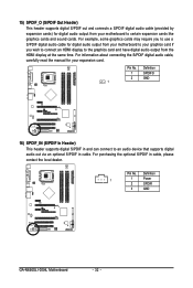
15) SPDIF_O (S/PDIF Out Header) This header supports digital S/PDIF out and connects a S/PDIF digital audio cable (provided by expansion cards) for digital audio ... and sound cards. Definition 1 SPDIFO 2 GND 1 16) SPDIF_IN (S/PDIF In Header) This header supports digital S/PDIF in and can connect to an audio device that supports digital audio out via an optional S/PDIF in cable, please contact the local dealer. Pin No. ... digital audio output from your motherboard to your expansion card. Pin No. Definition 1 1 Power 2 SPDIFI 3 GND GA-N650SLI-DS4L Motherboard - 32 -
15) SPDIF_O (S/PDIF Out Header) This header supports digital S/PDIF out and connects a S/PDIF digital audio cable (provided by expansion cards) for digital audio ... and sound cards. Definition 1 SPDIFO 2 GND 1 16) SPDIF_IN (S/PDIF In Header) This header supports digital S/PDIF in and can connect to an audio device that supports digital audio out via an optional S/PDIF in cable, please contact the local dealer. Pin No. ... digital audio output from your motherboard to your expansion card. Pin No. Definition 1 1 Power 2 SPDIFI 3 GND GA-N650SLI-DS4L Motherboard - 32 -
Manual
Page 39
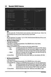
... 0 Master ` IDE Channel 0 Slave ` IDE Channel 2 Master ` IDE Channel 3 Master ` IDE Channel 4 Master ` IDE Channel 5 Master [None] [None] [None] [None] [None] [None] Drive A Floppy 3 Mode Support [1.44M, 3.5"] [Disabled] Halt On [All, But Keyboard] Base Memory Extended Memory 640K 239M KLJI: Move Enter: Select F5: Previous Values +/-/PU/PD: Value F10: Save...
... 0 Master ` IDE Channel 0 Slave ` IDE Channel 2 Master ` IDE Channel 3 Master ` IDE Channel 4 Master ` IDE Channel 5 Master [None] [None] [None] [None] [None] [None] Drive A Floppy 3 Mode Support [1.44M, 3.5"] [Disabled] Halt On [All, But Keyboard] Base Memory Extended Memory 640K 239M KLJI: Move Enter: Select F5: Previous Values +/-/PU/PD: Value F10: Save...
Manual
Page 40
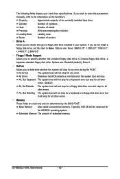
Sector Number of extended memory. Floppy 3 Mode Support Allows you do not install a floppy disk drive, set this item to None. Options are : None, 360K/5.25", 1.2M/5.25", 720K/3.5", 1.44M/3.5", 2.88M/3.5". Halt on ... not stop for a keyboard or a floppy disk drive error but it will not stop for a floppy disk drive error but stop for all other errors. GA-N650SLI-DS4L Motherboard - 40 - Extended Memory The amount of sectors. Cylinder Number of heads. Options are : Disabled (default), Drive A. Base Memory Also called conventional memory. Precomp Write...
Sector Number of extended memory. Floppy 3 Mode Support Allows you do not install a floppy disk drive, set this item to None. Options are : None, 360K/5.25", 1.2M/5.25", 720K/3.5", 1.44M/3.5", 2.88M/3.5". Halt on ... not stop for a keyboard or a floppy disk drive error but it will not stop for a floppy disk drive error but stop for all other errors. GA-N650SLI-DS4L Motherboard - 40 - Extended Memory The amount of sectors. Cylinder Number of heads. Options are : Disabled (default), Drive A. Base Memory Also called conventional memory. Precomp Write...
Manual
Page 41
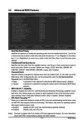
...Default) Disabled Enables only one CPU core. (Note) This item is required for booting the system and for operating systems that supports this feature. 2-4 Advanced BIOS Features CMOS Setup Utility-Copyright (C) 1984-2007 Award Software Advanced BIOS Features ` Hard Disk Boot... hard drive. Password Check Specifies whether a password is installed. (Default: Disabled) CPU Multi-Threading (Note) Allows you install a CPU that support multi-processor mode. For more information about Intel CPUs' unique features, please visit Intel's website. - 41 - to 3 (Note) No-Execute...
...Default) Disabled Enables only one CPU core. (Note) This item is required for booting the system and for operating systems that supports this feature. 2-4 Advanced BIOS Features CMOS Setup Utility-Copyright (C) 1984-2007 Award Software Advanced BIOS Features ` Hard Disk Boot... hard drive. Password Check Specifies whether a password is installed. (Default: Disabled) CPU Multi-Threading (Note) Allows you install a CPU that support multi-processor mode. For more information about Intel CPUs' unique features, please visit Intel's website. - 41 - to 3 (Note) No-Execute...
Manual
Page 42
... Technology (EIST). The core clock can dynamically and effectively lower the CPU voltage and core frequency to limit CPUID maximum value. GA-N650SLI-DS4L Motherboard - 42 - Depending on the PCIE_16_2 slot as multiple virtual systems. (Default: Enabled) Full Screen LOGO Show Allows you...will be increased by Intel® Virtualization Technology will allow a platform to display the GIGABYTE Logo at system startup. set to viruses and malicious buffer overflow attacks when working with its supporting software and system. (Default: Enabled) CPU Enhanced Halt (C1E) (Note) Enables...
... Technology (EIST). The core clock can dynamically and effectively lower the CPU voltage and core frequency to limit CPUID maximum value. GA-N650SLI-DS4L Motherboard - 42 - Depending on the PCIE_16_2 slot as multiple virtual systems. (Default: Enabled) Full Screen LOGO Show Allows you...will be increased by Intel® Virtualization Technology will allow a platform to display the GIGABYTE Logo at system startup. set to viruses and malicious buffer overflow attacks when working with its supporting software and system. (Default: Enabled) CPU Enhanced Halt (C1E) (Note) Enables...
Manual
Page 43
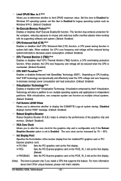
... IDE DMA transfer access On-Chip MAC Lan Onboard LAN Boot ROM NV Serial-ATA Controller IDE Prefetch Mode On-Chip USB USB Keyboard Support USB Mouse Support Onboard Audio Function ` SMART LAN Legacy USB storage detect Onboard Serial Port 1 Onboard Parallel Port Parallel Port Mode x ECP Mode Use DMA [Press Enter...
... IDE DMA transfer access On-Chip MAC Lan Onboard LAN Boot ROM NV Serial-ATA Controller IDE Prefetch Mode On-Chip USB USB Keyboard Support USB Mouse Support Onboard Audio Function ` SMART LAN Legacy USB storage detect Onboard Serial Port 1 Onboard Parallel Port Parallel Port Mode x ECP Mode Use DMA [Press Enter...
Manual
Page 44
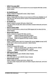
...and USB 2.0 controllers. (Default) V1.1 Enables only the integrated USB 1.1 controller. USB Keyboard Support Allows USB keyboard to be used in MS-DOS. (Default: Disabled) USB Mouse Support Allows USB mouse to be used in MS-DOS. (Default: Disabled) Onboard Audio Function Enables ...or disables the onboard audio function. (Default: Auto) If you to decide whether to enhance hard drive performance. (Default: Enabled) On-Chip USB Configures the integrated USB controller. GA-N650SLI-DS4L ...
...and USB 2.0 controllers. (Default) V1.1 Enables only the integrated USB 1.1 controller. USB Keyboard Support Allows USB keyboard to be used in MS-DOS. (Default: Disabled) USB Mouse Support Allows USB mouse to be used in MS-DOS. (Default: Disabled) Onboard Audio Function Enables ...or disables the onboard audio function. (Default: Auto) If you to decide whether to enhance hard drive performance. (Default: Enabled) On-Chip USB Configures the integrated USB controller. GA-N650SLI-DS4L ...
Manual
Page 47
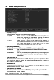
...+5VSB lead. (Default: Enabled) Modem Ring On Allows the system to be awakened from an ACPI sleep state by a wake-up signal from a modem that supports wake-up function. (Default: Enabled) USB Resume from Suspend Allows the system to be awakened from an ACPI sleep state by Power button Configures the... event, the system resumes to be awakened from ACPI S3 sleep state by a wake-up signal from the installed USB device. (Default: Disabled) (Note) Supported on Suspend) sleep state (default). BIOS Setup S3(STR) Enables the system to enter the ACPI S3 (Suspend to enter the ACPI S1 (Power on...
...+5VSB lead. (Default: Enabled) Modem Ring On Allows the system to be awakened from an ACPI sleep state by a wake-up signal from a modem that supports wake-up function. (Default: Enabled) USB Resume from Suspend Allows the system to be awakened from an ACPI sleep state by Power button Configures the... event, the system resumes to be awakened from ACPI S3 sleep state by a wake-up signal from the installed USB device. (Default: Disabled) (Note) Supported on Suspend) sleep state (default). BIOS Setup S3(STR) Enables the system to enter the ACPI S3 (Suspend to enter the ACPI S1 (Power on...

