
Manual
Page 4
... ItemChecklist ...6 OptionalAccessories ...6 GA-N650SLI-DS4 Motherboard Layout 7 Block Diagram ...8 Chapter 1 Hardware Installation 9 1-1 Considerations Prior to Installation 9 1-2 Feature Summary 10 1-3 Installation of the CPU and CPU Cooler 12 1-3-1 Installation of the CPU 12 1-3-2 Installation of the CPU Cooler 13 1-4 Installation of Memory 14 1-5 Installation of Expansion Cards 16 1-6 Setup of an SLI (Scalable Link Interface...
... ItemChecklist ...6 OptionalAccessories ...6 GA-N650SLI-DS4 Motherboard Layout 7 Block Diagram ...8 Chapter 1 Hardware Installation 9 1-1 Considerations Prior to Installation 9 1-2 Feature Summary 10 1-3 Installation of the CPU and CPU Cooler 12 1-3-1 Installation of the CPU 12 1-3-2 Installation of the CPU Cooler 13 1-4 Installation of Memory 14 1-5 Installation of Expansion Cards 16 1-6 Setup of an SLI (Scalable Link Interface...

Manual
Page 6
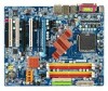
Item Checklist IDE Cable x 1 and FDD Cable x 1 SATA 3Gb/s Cable x 4 I/O Shield x 1 SLI Bridge (GC-DGBR2-RH) x 1 Retention Bracket x 1 * The items listed above are for reference only, and are subject to change without notice. Optional Accessories Š 2 Ports USB 2.0 Cable (Part Number: 12CR1-1UB030-51/R) Š 4 Ports USB 2.0 Cable (Part Number: 12CR1-1UB030-21/R) Š 2 Ports IEEE 1394 Cable (Part Number: 12CF1-1IE008-01R) Š S/PDIF-IN Cable (Part Number: 12CR1-1SPDIN-01R) Š e-SATA Cable (Part Number: 12CF1-3SATPW-11R) - 6 -
Item Checklist IDE Cable x 1 and FDD Cable x 1 SATA 3Gb/s Cable x 4 I/O Shield x 1 SLI Bridge (GC-DGBR2-RH) x 1 Retention Bracket x 1 * The items listed above are for reference only, and are subject to change without notice. Optional Accessories Š 2 Ports USB 2.0 Cable (Part Number: 12CR1-1UB030-51/R) Š 4 Ports USB 2.0 Cable (Part Number: 12CR1-1UB030-21/R) Š 2 Ports IEEE 1394 Cable (Part Number: 12CF1-1IE008-01R) Š S/PDIF-IN Cable (Part Number: 12CR1-1SPDIN-01R) Š e-SATA Cable (Part Number: 12CF1-3SATPW-11R) - 6 -

Manual
Page 8
... Bus PCI Express Bus x1 x1 PCIe CLK (100 MHz) LGA775 Processor CPU CLK+/-(333/266/200/133 MHz) Host Interface nVIDIA® nForce 650i SLI Northbridge DDRII 800/667/533 MHz DIMM Dual Channel Memory LAN RJ45 Marvell 88E1116 2 PCI Express x 1 PCI Bus TSB43AB23 nVIDIA® nForce 650i... SLI Southbridge 4 SATA 3Gb/s ATA 33/66/100/133 IDE Channels Dual BIOS LPC BUS IT8718 Floppy LPT Port CODEC COM Port 8 USB Ports PS/2 KB/...
... Bus PCI Express Bus x1 x1 PCIe CLK (100 MHz) LGA775 Processor CPU CLK+/-(333/266/200/133 MHz) Host Interface nVIDIA® nForce 650i SLI Northbridge DDRII 800/667/533 MHz DIMM Dual Channel Memory LAN RJ45 Marvell 88E1116 2 PCI Express x 1 PCI Bus TSB43AB23 nVIDIA® nForce 650i... SLI Southbridge 4 SATA 3Gb/s ATA 33/66/100/133 IDE Channels Dual BIOS LPC BUS IT8718 Floppy LPT Port CODEC COM Port 8 USB Ports PS/2 KB/...

Manual
Page 10
... 1 S/PDIF In connector Š 2 USB 2.0/1.1 connectors for additional 4 ports by cables Š 1 power LED connector Š 1 Chassis Intrusion connector GA-N650SLI-DS4 Motherboard - 10 - nection of 4 IDE devices - 4 SATA 3Gb/s connectors, allowing connection of 1 FDD device - 2 IDE connectors (UDMA 33/ATA ...66/ATA 100/ATA 133), allowing con- TSB43AB23 chip Storage Š 3 IEEE 1394a ports Š nVIDIA® nForce 650i SLI Southbridge - 1 FDD connector, allowing connection of 4 SATA 3Gb/s devices - English 1-2 Feature Summary CPU Š LGA775 for additional 2 ports...
... 1 S/PDIF In connector Š 2 USB 2.0/1.1 connectors for additional 4 ports by cables Š 1 power LED connector Š 1 Chassis Intrusion connector GA-N650SLI-DS4 Motherboard - 10 - nection of 4 IDE devices - 4 SATA 3Gb/s connectors, allowing connection of 1 FDD device - 2 IDE connectors (UDMA 33/ATA ...66/ATA 100/ATA 133), allowing con- TSB43AB23 chip Storage Š 3 IEEE 1394a ports Š nVIDIA® nForce 650i SLI Southbridge - 1 FDD connector, allowing connection of 4 SATA 3Gb/s devices - English 1-2 Feature Summary CPU Š LGA775 for additional 2 ports...

Manual
Page 11
... installed, the actual memory available for the operating system will be less than 4 GB; Windows 64-bit operating system doesn't have such limitation. (Note 2) In SLI Mode, the two PCIE x16 slots can run at up to x8 respectively. Hardware Installation
... installed, the actual memory available for the operating system will be less than 4 GB; Windows 64-bit operating system doesn't have such limitation. (Note 2) In SLI Mode, the two PCIE x16 slots can run at up to x8 respectively. Hardware Installation

Manual
Page 17
...the same model to bridge two nVIDIA® SLI-ready PCI ExpressTM graphics cards! We recommend a power supply that the exact power requirements will depend on the GA-N650SLI-DS4 motherboard. Enabling SLI Operation Setting the SLI switch module: The SLI switch module is to Normal Mode operation by... the edges and lift it in the SLI Mode direction. Hold the module by factory default, so the...
...the same model to bridge two nVIDIA® SLI-ready PCI ExpressTM graphics cards! We recommend a power supply that the exact power requirements will depend on the GA-N650SLI-DS4 motherboard. Enabling SLI Operation Setting the SLI switch module: The SLI switch module is to Normal Mode operation by... the edges and lift it in the SLI Mode direction. Hold the module by factory default, so the...

Manual
Page 18
... of the module with the key in the PCIE_16_1 and PCIE_16_2 slots. Step 2: Insert the SLI bridge into the socket. Female slots on the bridge connector Gold edge connector on the top of both cards. retention bracket GA-N650SLI-DS4 Motherboard - 18 - Make sure the two mini female slots on top of graphics card...
... of the module with the key in the PCIE_16_1 and PCIE_16_2 slots. Step 2: Insert the SLI bridge into the socket. Female slots on the bridge connector Gold edge connector on the top of both cards. retention bracket GA-N650SLI-DS4 Motherboard - 18 - Make sure the two mini female slots on top of graphics card...

Manual
Page 19
... First to PEG(Slot2). Then the SLI configuration is completed. (Note) For more information about software configurations for SLI, refer to the user's manual for display output. Step 2: Select SLI multi-GPU from the side menu and then select the Enable SLI multi-GPU checkbox in operating system, ...Installation click the NVIDIA icon in your graphics card. - 19 - Graphics Card Driver Setting: Step 1: After installing graphics card driver in the SLI multi-GPU dialog box. if you click Apply. English Step 4: Plug the display cable into the card on the PCIE_16_2 slot, set Init ...
... First to PEG(Slot2). Then the SLI configuration is completed. (Note) For more information about software configurations for SLI, refer to the user's manual for display output. Step 2: Select SLI multi-GPU from the side menu and then select the Enable SLI multi-GPU checkbox in operating system, ...Installation click the NVIDIA icon in your graphics card. - 19 - Graphics Card Driver Setting: Step 1: After installing graphics card driver in the SLI multi-GPU dialog box. if you click Apply. English Step 4: Plug the display cable into the card on the PCIE_16_2 slot, set Init ...


