Manual
Page 1
GA-MA790X-UD4P AM2+/AM2 socket motherboard for AMD PhenomTM II X3 processor/AMD PhenomTM II X4 processor/ AMD PhenomTM FX processor/AMD PhenomTM X4 processor/ AMD PhenomTM X3 processor/AMD AthlonTM X2 processor/ AMD AthlonTM processor/AMD SempronTM X2 processor/ AMD SempronTM processor User's Manual Rev. 1003 12ME-MA79U4P-1003R
GA-MA790X-UD4P AM2+/AM2 socket motherboard for AMD PhenomTM II X3 processor/AMD PhenomTM II X4 processor/ AMD PhenomTM FX processor/AMD PhenomTM X4 processor/ AMD PhenomTM X3 processor/AMD AthlonTM X2 processor/ AMD AthlonTM processor/AMD SempronTM X2 processor/ AMD SempronTM processor User's Manual Rev. 1003 12ME-MA79U4P-1003R
Manual
Page 3
All rights reserved. For product-related information, check on our website at: http://www.gigabyte.com.tw Identifying Your Motherboard Revision The revision number on your motherboard revision before updating motherboard BIOS, drivers, or when looking for technical information. Copyright © 2009 GIGA-BYTE TECHNOLOGY CO., LTD. Changes to their respective owners. For example, "REV...
All rights reserved. For product-related information, check on our website at: http://www.gigabyte.com.tw Identifying Your Motherboard Revision The revision number on your motherboard revision before updating motherboard BIOS, drivers, or when looking for technical information. Copyright © 2009 GIGA-BYTE TECHNOLOGY CO., LTD. Changes to their respective owners. For example, "REV...
Manual
Page 4
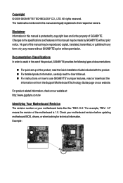
Table of Contents Box Contents ...6 OptionalItems ...6 GA-MA790X-UD4P Motherboard Layout 7 Block Diagram ...8 Chapter 1 Hardware Installation 9 1-1 Installation Precautions 9 1-2 Product Specifications 10 1-3 Installing the CPU and CPU Cooler 13 1-3-1 Installing the CPU 13 1-3-2 Installing the CPU ...
Table of Contents Box Contents ...6 OptionalItems ...6 GA-MA790X-UD4P Motherboard Layout 7 Block Diagram ...8 Chapter 1 Hardware Installation 9 1-1 Installation Precautions 9 1-2 Product Specifications 10 1-3 Installing the CPU and CPU Cooler 13 1-3-1 Installing the CPU 13 1-3-2 Installing the CPU ...

Manual
Page 6
...-1IE008-0*R) 2-port SATA power cable (Part No. 12CF1-2SERPW-0*R) COM port cable (Part No. 12CF1-1CM001-3*R) S/PDIF in cable (Part No. 12CR1-1SPDIN-0*R) - 6 - Box Contents GA-MA790X-UD4P motherboard Motherboard driver disk User's Manual Quick Installation Guide One IDE cable Four SATA 3Gb/s cables One SATA bracket I/O Shield • The box contents above are subject...
...-1IE008-0*R) 2-port SATA power cable (Part No. 12CF1-2SERPW-0*R) COM port cable (Part No. 12CF1-1CM001-3*R) S/PDIF in cable (Part No. 12CR1-1SPDIN-0*R) - 6 - Box Contents GA-MA790X-UD4P motherboard Motherboard driver disk User's Manual Quick Installation Guide One IDE cable Four SATA 3Gb/s cables One SATA bracket I/O Shield • The box contents above are subject...
Manual
Page 7
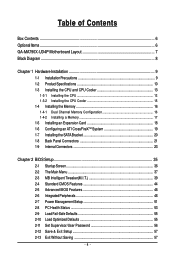
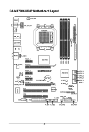
GA-MA790X-UD4P Motherboard Layout KB_MS CPU_FAN RCA_SPDIF ATX_12V_2X4 ATX R_USB Socket AM2 USB_1394_1 USB_1394 PWR_FAN USB IT8720 LAN AUDIO F_AUDIO PCIEX1_1 RTL8111C/D(L) PCIEX16_1 PCIEX1_2 CD_IN CODEC PCIEX1_3 SPDIF_IN SPDIF_OUT PCIEX8_1 PCI1 PCI2 COM FDD CI DDR2_1 DDR2_2 DDR2_3 DDR2_4 AMD 790X IDE GA-MA790X-UD4P CLR_CMOS BATTERY AMD SB750 B_BIOS M_BIOS SATA2_4 SATA2_5 SATA2_2 SATA2_3 SATA2_0 SATA2_1 TSB43AB23 GIGABYTE SATA2 GSATA2_0 GSATA2_1 PWR_LED F_USB1 F_PANEL F_1394 F_USB2 SYS_FAN2 SYS_FAN1 - 7 -
GA-MA790X-UD4P Motherboard Layout KB_MS CPU_FAN RCA_SPDIF ATX_12V_2X4 ATX R_USB Socket AM2 USB_1394_1 USB_1394 PWR_FAN USB IT8720 LAN AUDIO F_AUDIO PCIEX1_1 RTL8111C/D(L) PCIEX16_1 PCIEX1_2 CD_IN CODEC PCIEX1_3 SPDIF_IN SPDIF_OUT PCIEX8_1 PCI1 PCI2 COM FDD CI DDR2_1 DDR2_2 DDR2_3 DDR2_4 AMD 790X IDE GA-MA790X-UD4P CLR_CMOS BATTERY AMD SB750 B_BIOS M_BIOS SATA2_4 SATA2_5 SATA2_2 SATA2_3 SATA2_0 SATA2_1 TSB43AB23 GIGABYTE SATA2 GSATA2_0 GSATA2_1 PWR_LED F_USB1 F_PANEL F_1394 F_USB2 SYS_FAN2 SYS_FAN1 - 7 -
Manual
Page 9
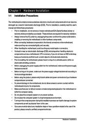
... of the product, please consult a certified computer technician. - 9 - Hardware Installation Chapter 1 Hardware Installation 1-1 Installation Precautions The motherboard contains numerous delicate electronic circuits and components which can lead to damage to system components as well as physical harm to the user... environment. • Turning on the power, make sure they are connected tightly and securely. • When handling the motherboard, avoid touching any installation steps or have a problem related to the use of electrostatic discharge (ESD). Prior to installation,...
... of the product, please consult a certified computer technician. - 9 - Hardware Installation Chapter 1 Hardware Installation 1-1 Installation Precautions The motherboard contains numerous delicate electronic circuits and components which can lead to damage to system components as well as physical harm to the user... environment. • Turning on the power, make sure they are connected tightly and securely. • When handling the motherboard, avoid touching any installation steps or have a problem related to the use of electrostatic discharge (ESD). Prior to installation,...
Manual
Page 10
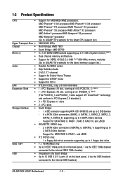
...GB of system memory (Note 1) Dual channel memory architecture Support for DDR2 1333(O.C.)/1066 (Note 2)/800 MHz memory modules (Go to GIGABYTE's website for the latest memory support list.) Realtek ALC889A codec High Definition Audio 2/4/5.1/7.1-channel Support for Dolby® Home Theater Support for..., SATA2_1, SATA2_2, SATA2_3, SATA2_4, SATA2_5) supporting up to 2 SATA 3Gb/s devices - Support for SATA RAID 0, RAID 1, RAID 5, RAID 10, and JBOD GIGABYTE SATA2 chip: - 2 x SATA 3Gb/s connectors (GSATA2_0, GSATA2_1) supporting up to the internal USB headers) GA-MA790X-UD4P Motherboard - 10 -
...GB of system memory (Note 1) Dual channel memory architecture Support for DDR2 1333(O.C.)/1066 (Note 2)/800 MHz memory modules (Go to GIGABYTE's website for the latest memory support list.) Realtek ALC889A codec High Definition Audio 2/4/5.1/7.1-channel Support for Dolby® Home Theater Support for..., SATA2_1, SATA2_2, SATA2_3, SATA2_4, SATA2_5) supporting up to 2 SATA 3Gb/s devices - Support for SATA RAID 0, RAID 1, RAID 5, RAID 10, and JBOD GIGABYTE SATA2 chip: - 2 x SATA 3Gb/s connectors (GSATA2_0, GSATA2_1) supporting up to the internal USB headers) GA-MA790X-UD4P Motherboard - 10 -
Manual
Page 12
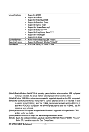
When PCIEX8_1 is populated with the PCIEX16_1 slot. GA-MA790X-UD4P Motherboard - 12 - The PCIEX8_1 slot shares bandwidth with a PCI Express graphics card, the PCIEX16_1 slot will depend on the CPU being used. (Note 3) For optimum performance, .../system fan speed control function is to be installed, be sure to the hardware limitation, you install. (Note 5) Available functions in EasyTune may differ by motherboard model. (Note 6) Due to install it in the PCIEX16_1 slot. Unique Features Bundled Software Operating System Form Factor Support for @BIOS Support for...
When PCIEX8_1 is populated with the PCIEX16_1 slot. GA-MA790X-UD4P Motherboard - 12 - The PCIEX8_1 slot shares bandwidth with a PCI Express graphics card, the PCIEX16_1 slot will depend on the CPU being used. (Note 3) For optimum performance, .../system fan speed control function is to be installed, be sure to the hardware limitation, you install. (Note 5) Available functions in EasyTune may differ by motherboard model. (Note 6) Due to install it in the PCIEX16_1 slot. Unique Features Bundled Software Operating System Form Factor Support for @BIOS Support for...

Manual
Page 13
... CPU host frequency in accordance with the CPU specifications. It is not installed, otherwise overheating and damage of the CPU. mended that the motherboard supports the CPU. (Go to GIGABYTE's website for the peripherals. Hardware Installation 1-3 Installing the CPU and CPU Cooler Read the following guidelines before installing the CPU to prevent...
... CPU host frequency in accordance with the CPU specifications. It is not installed, otherwise overheating and damage of the CPU. mended that the motherboard supports the CPU. (Go to GIGABYTE's website for the peripherals. Hardware Installation 1-3 Installing the CPU and CPU Cooler Read the following guidelines before installing the CPU to prevent...
Manual
Page 14
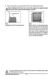
GA-MA790X-UD4P Motherboard - 14 - Before installing the CPU, make sure to turn off the computer and unplug the power cord from the power outlet to prevent damage to correctly install the CPU into the motherboard CPU socket. Step 2: Align the CPU pin one finger down on the CPU socket and gently insert the CPU into...
GA-MA790X-UD4P Motherboard - 14 - Before installing the CPU, make sure to turn off the computer and unplug the power cord from the power outlet to prevent damage to correctly install the CPU into the motherboard CPU socket. Step 2: Align the CPU pin one finger down on the CPU socket and gently insert the CPU into...
Manual
Page 15
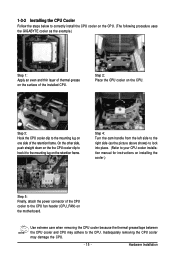
... to the CPU. On the other side, push straight down on the the CPU cooler clip to hook it to the mounting lug on the motherboard. Use extreme care when removing the CPU cooler because the thermal grease/tape between the CPU cooler and CPU may damage the CPU. - 15 - ...the installed CPU. 1-3-2 Installing the CPU Cooler Follow the steps below to correctly install the CPU cooler on the CPU. (The following procedure uses the GIGABYTE cooler as the picture above shows) to lock into place. (Refer to your CPU cooler installation manual for instructions on installing the cooler.) Step 5: Finally...
... to the CPU. On the other side, push straight down on the the CPU cooler clip to hook it to the mounting lug on the motherboard. Use extreme care when removing the CPU cooler because the thermal grease/tape between the CPU cooler and CPU may damage the CPU. - 15 - ...the installed CPU. 1-3-2 Installing the CPU Cooler Follow the steps below to correctly install the CPU cooler on the CPU. (The following procedure uses the GIGABYTE cooler as the picture above shows) to lock into place. (Refer to your CPU cooler installation manual for instructions on installing the cooler.) Step 5: Finally...
Manual
Page 16
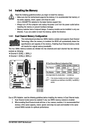
...cannot be used . (Go to prevent hardware damage. • Memory modules have a foolproof design. After the memory is installed. 2. GA-MA790X-UD4P Motherboard - 16 - If you install them in the same colored DDR2 sockets for the latest memory support list.) • Always turn off the..., "- -"=No Memory) If two memory modules are unable to CPU limitation, read the following guidelines before installing the memory to GIGABYTE's website for optimum performance. Enabling Dual Channel memory mode will automatically detect the specifications and capacity of the same capacity, brand,...
...cannot be used . (Go to prevent hardware damage. • Memory modules have a foolproof design. After the memory is installed. 2. GA-MA790X-UD4P Motherboard - 16 - If you install them in the same colored DDR2 sockets for the latest memory support list.) • Always turn off the..., "- -"=No Memory) If two memory modules are unable to CPU limitation, read the following guidelines before installing the memory to GIGABYTE's website for optimum performance. Enabling Dual Channel memory mode will automatically detect the specifications and capacity of the same capacity, brand,...
Manual
Page 17
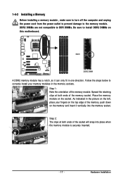
Follow the steps below to the memory module. Place the memory module on this motherboard. Step 2: The clips at both ends of the socket will snap into the memory socket. Hardware Installation Notch DDR2 DIMM A DDR2 memory module has a notch, ...
Follow the steps below to the memory module. Place the memory module on this motherboard. Step 2: The clips at both ends of the socket will snap into the memory socket. Hardware Installation Notch DDR2 DIMM A DDR2 memory module has a notch, ...

Manual
Page 18
..., go to BIOS Setup to the chassis back panel with the expansion card in the slot. 3. Install the driver provided with a screw. 5. GA-MA790X-UD4P Motherboard - 18 - • Removing the Card from the PCIEX8_1 slot: Press the white latch at the end of the card until it is securely seated... Slot (PCIEX16_1) PCI Express x16 Slot (PCIEX8_1) PCI Slot Follow the steps below to install an expansion card: • Make sure the motherboard supports the expansion card. Align the card with your card. After installing all expansion cards, replace the chassis cover(s). 6. Make sure the card...
..., go to BIOS Setup to the chassis back panel with the expansion card in the slot. 3. Install the driver provided with a screw. 5. GA-MA790X-UD4P Motherboard - 18 - • Removing the Card from the PCIEX8_1 slot: Press the white latch at the end of the card until it is securely seated... Slot (PCIEX16_1) PCI Express x16 Slot (PCIEX8_1) PCI Slot Follow the steps below to install an expansion card: • Make sure the motherboard supports the expansion card. Align the card with your card. After installing all expansion cards, replace the chassis cover(s). 6. Make sure the card...

Manual
Page 20
.... • Insert the SATA signal cable and SATA power cable securely into to install the SATA bracket: Step 1: Locate one SATA power cable. GA-MA790X-UD4P Motherboard - 20 - Step 3: Step 4: Connect the power Plug one end of the SATA signal cable and SATA power cable to the power connector on... bracket allows you only need to connect the SATA signal cable. Before connecting the SATA signal cable, make sure to turn off your motherboard. Follow the steps below to the power supply. Step 2: Connect the SATA cable from the bracket SATA signal cable into the corresponding ...
.... • Insert the SATA signal cable and SATA power cable securely into to install the SATA bracket: Step 1: Locate one SATA power cable. GA-MA790X-UD4P Motherboard - 20 - Step 3: Step 4: Connect the power Plug one end of the SATA signal cable and SATA power cable to the power connector on... bracket allows you only need to connect the SATA signal cable. Before connecting the SATA signal cable, make sure to turn off your motherboard. Follow the steps below to the power supply. Step 2: Connect the SATA cable from the bracket SATA signal cable into the corresponding ...

Manual
Page 21
... as an USB keyboard/mouse, USB printer, USB flash drive and etc. Use this feature, ensure that your device and then remove it from the motherboard. • When removing the cable, pull it side to side to a back panel connector, first remove the cable from your audio system provides an optical...
... as an USB keyboard/mouse, USB printer, USB flash drive and etc. Use this feature, ensure that your device and then remove it from the motherboard. • When removing the cable, pull it side to side to a back panel connector, first remove the cable from your audio system provides an optical...

Manual
Page 22
... to the default speakers settings, the ~ audio jacks can be connected to this jack. Line In Jack (Blue) The default line in a 4/5.1/7.1-channel audio configuration. GA-MA790X-UD4P Motherboard - 22 - Line Out Jack (Green) The default line out jack. Only microphones still MUST be reconfigured to perform different functions via the audio software. This...
... to the default speakers settings, the ~ audio jacks can be connected to this jack. Line In Jack (Blue) The default line in a 4/5.1/7.1-channel audio configuration. GA-MA790X-UD4P Motherboard - 22 - Line Out Jack (Green) The default line out jack. Only microphones still MUST be reconfigured to perform different functions via the audio software. This...
Manual
Page 23
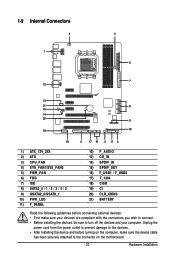
... 14) SPDIF_IN 15) SPDIF_OUT 16) F_USB1 / F_USB2 17) F_1394 18) COM 19) CI 20) CLR_CMOS 21) BATTERY Read the following guidelines before turning on the motherboard. - 23 - Unplug the power cord from the power outlet to prevent damage to the devices. • After installing the device and before connecting external devices...
... 14) SPDIF_IN 15) SPDIF_OUT 16) F_USB1 / F_USB2 17) F_1394 18) COM 19) CI 20) CLR_CMOS 21) BATTERY Read the following guidelines before turning on the motherboard. - 23 - Unplug the power cord from the power outlet to prevent damage to the devices. • After installing the device and before connecting external devices...
Manual
Page 24
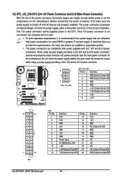
...12V GND PS_ON(soft On/Off) GND GND GND -5V +5V +5V +5V (Only for 2x12-pin ATX) GND (Only for 2x12-pin ATX) GA-MA790X-UD4P Motherboard - 24 - The 12V power connector mainly supplies power to the power connector in the correct orientation. When using a power supply providing a 2x2 12V ...connector possesses a foolproof design. Before connecting the power connector, first make sure the power supply is turned off and all the components on the motherboard. Do not insert the power supply cables into pins under the protective covers when using a power supply providing a 2x4 12V and a 2x12...
...12V GND PS_ON(soft On/Off) GND GND GND -5V +5V +5V +5V (Only for 2x12-pin ATX) GND (Only for 2x12-pin ATX) GA-MA790X-UD4P Motherboard - 24 - The 12V power connector mainly supplies power to the power connector in the correct orientation. When using a power supply providing a 2x2 12V ...connector possesses a foolproof design. Before connecting the power connector, first make sure the power supply is turned off and all the components on the motherboard. Do not insert the power supply cables into pins under the protective covers when using a power supply providing a 2x4 12V and a 2x12...

Manual
Page 25
Most fan headers possess a foolproof insertion design. The motherboard supports CPU fan speed control, which requires the use of floppy disk drives supported are not configuration jumper blocks. Do not place a jumper ...Drive Connector) This connector is typically designated by a stripe of different color. 33 1 34 2 - 25 - Hardware Installation 3/4/5) CPU_FAN / SYS_FAN1 / SYS_FAN2 / PWR_FAN (Fan Headers) The motherboard has a 4-pin CPU fan header (CPU_FAN), a 4-pin (SYS_FAN1) and two 3-pin (SYS_FAN2) system fan headers, and a 3-pin power fan header (PWR_FAN). Overheating may hang. &#...
Most fan headers possess a foolproof insertion design. The motherboard supports CPU fan speed control, which requires the use of floppy disk drives supported are not configuration jumper blocks. Do not place a jumper ...Drive Connector) This connector is typically designated by a stripe of different color. 33 1 34 2 - 25 - Hardware Installation 3/4/5) CPU_FAN / SYS_FAN1 / SYS_FAN2 / PWR_FAN (Fan Headers) The motherboard has a 4-pin CPU fan header (CPU_FAN), a 4-pin (SYS_FAN1) and two 3-pin (SYS_FAN2) system fan headers, and a 3-pin power fan header (PWR_FAN). Overheating may hang. &#...


