Manual
Page 1
GA-MA790X-UD4P AM2+/AM2 socket motherboard for AMD PhenomTM II X3 processor/AMD PhenomTM II X4 processor/ AMD PhenomTM FX processor/AMD PhenomTM X4 processor/ AMD PhenomTM X3 processor/AMD AthlonTM X2 processor/ AMD AthlonTM processor/AMD SempronTM X2 processor/ AMD SempronTM processor User's Manual Rev. 1003 12ME-MA79U4P-1003R
GA-MA790X-UD4P AM2+/AM2 socket motherboard for AMD PhenomTM II X3 processor/AMD PhenomTM II X4 processor/ AMD PhenomTM FX processor/AMD PhenomTM X4 processor/ AMD PhenomTM X3 processor/AMD AthlonTM X2 processor/ AMD AthlonTM processor/AMD SempronTM X2 processor/ AMD SempronTM processor User's Manual Rev. 1003 12ME-MA79U4P-1003R
Manual
Page 4
Table of Contents Box Contents ...6 OptionalItems ...6 GA-MA790X-UD4P Motherboard Layout 7 Block Diagram ...8 Chapter 1 Hardware Installation 9 1-1 Installation Precautions 9 1-2 Product Specifications 10 1-3 Installing the CPU and CPU Cooler 13 1-3-1 Installing the CPU 13 1-3-2 Installing the ...
Table of Contents Box Contents ...6 OptionalItems ...6 GA-MA790X-UD4P Motherboard Layout 7 Block Diagram ...8 Chapter 1 Hardware Installation 9 1-1 Installation Precautions 9 1-2 Product Specifications 10 1-3 Installing the CPU and CPU Cooler 13 1-3-1 Installing the CPU 13 1-3-2 Installing the ...

Manual
Page 6
Box Contents GA-MA790X-UD4P motherboard Motherboard driver disk User's Manual Quick Installation Guide One IDE cable Four SATA 3Gb/s cables One SATA bracket I/O Shield • The box contents above ...
Box Contents GA-MA790X-UD4P motherboard Motherboard driver disk User's Manual Quick Installation Guide One IDE cable Four SATA 3Gb/s cables One SATA bracket I/O Shield • The box contents above ...
Manual
Page 7
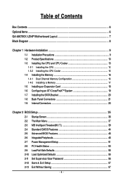
GA-MA790X-UD4P Motherboard Layout KB_MS CPU_FAN RCA_SPDIF ATX_12V_2X4 ATX R_USB Socket AM2 USB_1394_1 USB_1394 PWR_FAN USB IT8720 LAN AUDIO F_AUDIO PCIEX1_1 RTL8111C/D(L) PCIEX16_1 PCIEX1_2 CD_IN CODEC PCIEX1_3 SPDIF_IN SPDIF_OUT PCIEX8_1 PCI1 PCI2 COM FDD CI DDR2_1 DDR2_2 DDR2_3 DDR2_4 AMD 790X IDE GA-MA790X-UD4P CLR_CMOS BATTERY AMD SB750 B_BIOS M_BIOS SATA2_4 SATA2_5 SATA2_2 SATA2_3 SATA2_0 SATA2_1 TSB43AB23 GIGABYTE SATA2 GSATA2_0 GSATA2_1 PWR_LED F_USB1 F_PANEL F_1394 F_USB2 SYS_FAN2 SYS_FAN1 - 7 -
GA-MA790X-UD4P Motherboard Layout KB_MS CPU_FAN RCA_SPDIF ATX_12V_2X4 ATX R_USB Socket AM2 USB_1394_1 USB_1394 PWR_FAN USB IT8720 LAN AUDIO F_AUDIO PCIEX1_1 RTL8111C/D(L) PCIEX16_1 PCIEX1_2 CD_IN CODEC PCIEX1_3 SPDIF_IN SPDIF_OUT PCIEX8_1 PCI1 PCI2 COM FDD CI DDR2_1 DDR2_2 DDR2_3 DDR2_4 AMD 790X IDE GA-MA790X-UD4P CLR_CMOS BATTERY AMD SB750 B_BIOS M_BIOS SATA2_4 SATA2_5 SATA2_2 SATA2_3 SATA2_0 SATA2_1 TSB43AB23 GIGABYTE SATA2 GSATA2_0 GSATA2_1 PWR_LED F_USB1 F_PANEL F_1394 F_USB2 SYS_FAN2 SYS_FAN1 - 7 -
Manual
Page 10
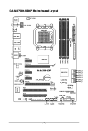
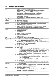
...system memory (Note 1) Dual channel memory architecture Support for DDR2 1333(O.C.)/1066 (Note 2)/800 MHz memory modules (Go to GIGABYTE's website for the latest memory support list.) Realtek ALC889A codec High Definition Audio 2/4/5.1/7.1-channel Support for Dolby® Home Theater ... up to the internal USB headers) GA-MA790X-UD4P Motherboard - 10 - Support for SATA RAID 0, RAID 1, and JBOD iTE IT8720 chip: - 1 x floppy disk drive connector supporting up to 1 floppy disk drive T.I. Support for SATA RAID 0, RAID 1, RAID 5, RAID 10, and JBOD GIGABYTE SATA2 chip: - 2 x SATA 3Gb...
...system memory (Note 1) Dual channel memory architecture Support for DDR2 1333(O.C.)/1066 (Note 2)/800 MHz memory modules (Go to GIGABYTE's website for the latest memory support list.) Realtek ALC889A codec High Definition Audio 2/4/5.1/7.1-channel Support for Dolby® Home Theater ... up to the internal USB headers) GA-MA790X-UD4P Motherboard - 10 - Support for SATA RAID 0, RAID 1, and JBOD iTE IT8720 chip: - 1 x floppy disk drive connector supporting up to 1 floppy disk drive T.I. Support for SATA RAID 0, RAID 1, RAID 5, RAID 10, and JBOD GIGABYTE SATA2 chip: - 2 x SATA 3Gb...
Manual
Page 12
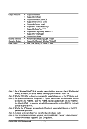
....3cm (Note 1) Due to the hardware limitation, you must install the AMD AM3 PhenomTM II/AM2+ PhenomTM Series CPU toenable support for Easy Energy Saver. GA-MA790X-UD4P Motherboard - 12 - When PCIEX8_1 is populated with the PCIEX16_1 slot.
....3cm (Note 1) Due to the hardware limitation, you must install the AMD AM3 PhenomTM II/AM2+ PhenomTM Series CPU toenable support for Easy Energy Saver. GA-MA790X-UD4P Motherboard - 12 - When PCIEX8_1 is populated with the PCIEX16_1 slot.
Manual
Page 14
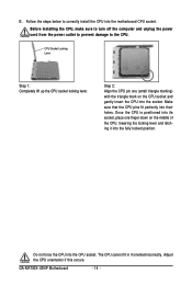
... pin one finger down on the CPU socket and gently insert the CPU into the motherboard CPU socket. Adjust the CPU orientation if this occurs. GA-MA790X-UD4P Motherboard - 14 - Make sure that the CPU pins fit perfectly into the CPU socket. B. The CPU cannot fit in if oriented incorrectly. Before installing the...
... pin one finger down on the CPU socket and gently insert the CPU into the motherboard CPU socket. Adjust the CPU orientation if this occurs. GA-MA790X-UD4P Motherboard - 14 - Make sure that the CPU pins fit perfectly into the CPU socket. B. The CPU cannot fit in if oriented incorrectly. Before installing the...
Manual
Page 16
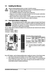
.../SS (SS=Single-Sided, DS=Double-Sided, "- -"=No Memory) If two memory modules are to be installed, it is recommended that memory of the memory. GA-MA790X-UD4P Motherboard - 16 - If you are divided into two channels and each channel has two memory sockets as following: Channel 0: DDR2_1, DDR2_3 Channel 1: DDR2_2, DDR2_4 Dual... specifications and capacity of the same capacity, brand, speed, and chips be used . (Go to install the memory: • Make sure that you begin to GIGABYTE's website for optimum performance.
.../SS (SS=Single-Sided, DS=Double-Sided, "- -"=No Memory) If two memory modules are to be installed, it is recommended that memory of the memory. GA-MA790X-UD4P Motherboard - 16 - If you are divided into two channels and each channel has two memory sockets as following: Channel 0: DDR2_1, DDR2_3 Channel 1: DDR2_2, DDR2_4 Dual... specifications and capacity of the same capacity, brand, speed, and chips be used . (Go to install the memory: • Make sure that you begin to GIGABYTE's website for optimum performance.

Manual
Page 18
... a Graphics Card: Gently push down on the card until it is fully seated in the slot. 3. After installing all expansion cards, replace the chassis cover(s). 6. GA-MA790X-UD4P Motherboard - 18 - • Removing the Card from the slot. Locate an expansion slot that came with the slot, and press down on your computer. If...
... a Graphics Card: Gently push down on the card until it is fully seated in the slot. 3. After installing all expansion cards, replace the chassis cover(s). 6. GA-MA790X-UD4P Motherboard - 18 - • Removing the Card from the slot. Locate an expansion slot that came with the slot, and press down on your computer. If...

Manual
Page 20
... from the bracket SATA signal cable into the corresponding connectors when installing. Then attach the SATA power cable to the power connector on your motherboard. GA-MA790X-UD4P Motherboard - 20 - Connect the other ends of the external enclosure. Before connecting the SATA signal cable, make sure to turn off your SATA device. Step...
... from the bracket SATA signal cable into the corresponding connectors when installing. Then attach the SATA power cable to the power connector on your motherboard. GA-MA790X-UD4P Motherboard - 20 - Connect the other ends of the external enclosure. Before connecting the SATA signal cable, make sure to turn off your SATA device. Step...

Manual
Page 22
Side Speaker Out Jack (Gray) Use this audio jack for a headphone or 2-channel speaker. GA-MA790X-UD4P Motherboard - 22 - Use this audio jack to connect side speakers in a 4/5.1/7.1-channel audio configuration. Use this audio jack to connect front speakers in a 5.1/7.1-channel audio ...
Side Speaker Out Jack (Gray) Use this audio jack for a headphone or 2-channel speaker. GA-MA790X-UD4P Motherboard - 22 - Use this audio jack to connect side speakers in a 4/5.1/7.1-channel audio configuration. Use this audio jack to connect front speakers in a 5.1/7.1-channel audio ...
Manual
Page 24
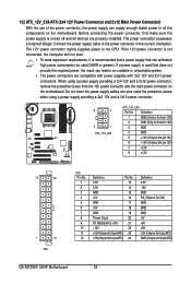
... 3.3V -12V GND PS_ON(soft On/Off) GND GND GND -5V +5V +5V +5V (Only for 2x12-pin ATX) GND (Only for 2x12-pin ATX) GA-MA790X-UD4P Motherboard - 24 - The power connector possesses a foolproof design. The 12V power connector mainly supplies power to an unstable or unbootable system. • The power connectors...
... 3.3V -12V GND PS_ON(soft On/Off) GND GND GND -5V +5V +5V +5V (Only for 2x12-pin ATX) GND (Only for 2x12-pin ATX) GA-MA790X-UD4P Motherboard - 24 - The power connector possesses a foolproof design. The 12V power connector mainly supplies power to an unstable or unbootable system. • The power connectors...
Manual
Page 26
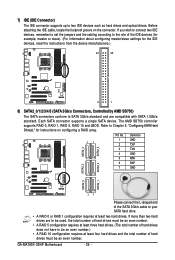
... drives are to SATA 3Gb/s standard and are compatible with SATA 1.5Gb/s standard. The AMD SB750 controller supports RAID 0, RAID 1, RAID 5, RAID 10 and JBOD. GA-MA790X-UD4P Motherboard - 26 - 7) IDE (IDE Connector) The IDE connector supports up to Chapter 5, "Configuring SATA Hard Drive(s)," for the IDE devices, read the instructions from the...
... drives are to SATA 3Gb/s standard and are compatible with SATA 1.5Gb/s standard. The AMD SB750 controller supports RAID 0, RAID 1, RAID 5, RAID 10 and JBOD. GA-MA790X-UD4P Motherboard - 26 - 7) IDE (IDE Connector) The IDE connector supports up to Chapter 5, "Configuring SATA Hard Drive(s)," for the IDE devices, read the instructions from the...
Manual
Page 28
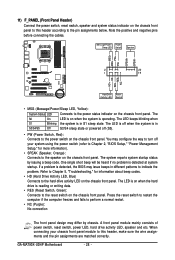
... panel design may configure the way to turn off (S5). • PW (Power Switch, Red): Connects to the power switch on the chassis front panel. GA-MA790X-UD4P Motherboard - 28 - The LED keeps blinking when S1 Blinking the system is detected at system startup. Message/Power/ Power Sleep LED Switch Speaker MSG+ MSG...
... panel design may configure the way to turn off (S5). • PW (Power Switch, Red): Connects to the power switch on the chassis front panel. GA-MA790X-UD4P Motherboard - 28 - The LED keeps blinking when S1 Blinking the system is detected at system startup. Message/Power/ Power Sleep LED Switch Speaker MSG+ MSG...
Manual
Page 30
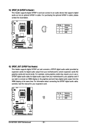
... you wish to connect an HDMI display to the graphics card and have digital audio output from your expansion card. Pin No. Definition 1 SPDIFO 1 2 GND GA-MA790X-UD4P Motherboard - 30 - Definition 1 1 Power 2 SPDIFI 3 GND 15) SPDIF_OUT (S/PDIF Out Header) This header supports digital S/PDIF out and connects a S/PDIF digital audio cable (provided by...
... you wish to connect an HDMI display to the graphics card and have digital audio output from your expansion card. Pin No. Definition 1 SPDIFO 1 2 GND GA-MA790X-UD4P Motherboard - 30 - Definition 1 1 Power 2 SPDIFI 3 GND 15) SPDIF_OUT (S/PDIF Out Header) This header supports digital S/PDIF out and connects a S/PDIF digital audio cable (provided by...
Manual
Page 32
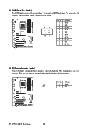
Pin No. 18) COM (Serial Port Header) The COM header can provide one serial port via an optional COM port cable. This function requires a chassis with chassis intrusion detection design. For purchasing the optional COM port cable, please contact the local dealer. 9 1 10 2 Pin No. 1 2 3 4 5 6 7 8 9 10 Definition NDCD NSIN NSOUT NDTR GND NDSR NRTS NCTS NRI No Pin 19) CI (Chassis Intrusion Header) This motherboard provides a chassis detection feature that detects if the chassis cover has been removed. Definition 1 Signal 1 2 GND GA-MA790X-UD4P Motherboard - 32 -
Pin No. 18) COM (Serial Port Header) The COM header can provide one serial port via an optional COM port cable. This function requires a chassis with chassis intrusion detection design. For purchasing the optional COM port cable, please contact the local dealer. 9 1 10 2 Pin No. 1 2 3 4 5 6 7 8 9 10 Definition NDCD NSIN NSOUT NDTR GND NDSR NRTS NCTS NRI No Pin 19) CI (Chassis Intrusion Header) This motherboard provides a chassis detection feature that detects if the chassis cover has been removed. Definition 1 Signal 1 2 GND GA-MA790X-UD4P Motherboard - 32 -
Manual
Page 36
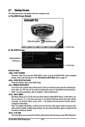
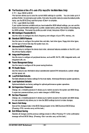
... BIOS v6.00PG, An Energy Star Ally Copyright (C) 1984-2009, Award Software, Inc. The system will still be used for one time only. GA-MA790X-UD4P Motherboard - 36 - To show the BIOS POST screen. A. In Boot Menu, use the up hard drive data using the motherboard driver disk, ...-SB750-7A66AG08C-00 Function Keys Function Keys: : POST SCREEN Press the key to set the first boot device without having to XpressRecovery2 during the POST. GA-MA790X-UD4P E3 . . . . You can be based on page 47. : BIOS SETUP\Q-FLASH Press the key to enter BIOS Setup. : XPRESS RECOVERY2 ...
... BIOS v6.00PG, An Energy Star Ally Copyright (C) 1984-2009, Award Software, Inc. The system will still be used for one time only. GA-MA790X-UD4P Motherboard - 36 - To show the BIOS POST screen. A. In Boot Menu, use the up hard drive data using the motherboard driver disk, ...-SB750-7A66AG08C-00 Function Keys Function Keys: : POST SCREEN Press the key to set the first boot device without having to XpressRecovery2 during the POST. GA-MA790X-UD4P E3 . . . . You can be based on page 47. : BIOS SETUP\Q-FLASH Press the key to enter BIOS Setup. : XPRESS RECOVERY2 ...
Manual
Page 38
... This function allows you to save the current BIOS settings to the confirmation message will exit BIOS Setup. (Pressing can also carry out this task.) GA-MA790X-UD4P Motherboard - 38 - You can use this menu to see information about autodetected system/CPU temperature, system voltage and fan speed, etc. Load Fail-Safe...
... This function allows you to save the current BIOS settings to the confirmation message will exit BIOS Setup. (Pressing can also carry out this task.) GA-MA790X-UD4P Motherboard - 38 - You can use this menu to see information about autodetected system/CPU temperature, system voltage and fan speed, etc. Load Fail-Safe...
Manual
Page 40
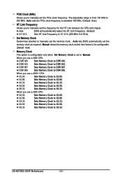
.... When you use a AM3 CPU: X2.00 Sets Memory Clock to X2.00. Set Memory Clock Determines whether to manually set the PCIe clock frequency. GA-MA790X-UD4P Motherboard - 40 - When you use a AM2 CPU: DDR 400 Sets Memory Clock to DDR 400. X3.33 Sets Memory Clock to DDR 533. PCIE Clock...
.... When you use a AM3 CPU: X2.00 Sets Memory Clock to X2.00. Set Memory Clock Determines whether to manually set the PCIe clock frequency. GA-MA790X-UD4P Motherboard - 40 - When you use a AM2 CPU: DDR 400 Sets Memory Clock to DDR 400. X3.33 Sets Memory Clock to DDR 533. PCIE Clock...
Manual
Page 42
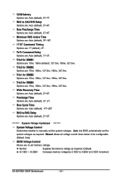
... Options are: Auto (default), 5T~18T. 1T/2T Command Timing Options are : Auto (default), 3T~7T. Trfc1 for DIMM2 Options are : Auto (default), 11T~26T. GA-MA790X-UD4P Motherboard - 42 - RAS to set memory voltage. Normal Supplies the memory voltage as required. (Default) +0.100V ~ +0.600V Increases memory voltage by 0.100V to manually set...
... Options are: Auto (default), 5T~18T. 1T/2T Command Timing Options are : Auto (default), 3T~7T. Trfc1 for DIMM2 Options are : Auto (default), 11T~26T. GA-MA790X-UD4P Motherboard - 42 - RAS to set memory voltage. Normal Supplies the memory voltage as required. (Default) +0.100V ~ +0.600V Increases memory voltage by 0.100V to manually set...


