Manual
Page 4
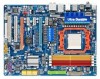
Table of Contents Box Contents ...6 OptionalItems ...6 GA-MA790X-UD4P Motherboard Layout 7 Block Diagram ...8 Chapter 1 Hardware Installation 9 1-1 Installation Precautions 9 1-2 Product Specifications 10 1-3 Installing the CPU and CPU Cooler 13 1-3-1 ... Startup Screen 36 2-2 The Main Menu 37 2-3 MB Intelligent Tweaker(M.I.T 39 2-4 Standard CMOS Features 44 2-5 Advanced BIOS Features 46 2-6 IntegratedPeripherals 48 2-7 Power Management Setup 51 2-8 PC Health Status 53 2-9 Load Fail-Safe Defaults 55 2-10 Load Optimized Defaults 55 2-11 Set Supervisor/User Password 56 2-12...
Table of Contents Box Contents ...6 OptionalItems ...6 GA-MA790X-UD4P Motherboard Layout 7 Block Diagram ...8 Chapter 1 Hardware Installation 9 1-1 Installation Precautions 9 1-2 Product Specifications 10 1-3 Installing the CPU and CPU Cooler 13 1-3-1 ... Startup Screen 36 2-2 The Main Menu 37 2-3 MB Intelligent Tweaker(M.I.T 39 2-4 Standard CMOS Features 44 2-5 Advanced BIOS Features 46 2-6 IntegratedPeripherals 48 2-7 Power Management Setup 51 2-8 PC Health Status 53 2-9 Load Fail-Safe Defaults 55 2-10 Load Optimized Defaults 55 2-11 Set Supervisor/User Password 56 2-12...

Manual
Page 6
... (Part No. 12CR1-1UB030-5*R) 2-port IEEE 1394a bracket (Part No. 12CF1-1IE008-0*R) 2-port SATA power cable (Part No. 12CF1-2SERPW-0*R) COM port cable (Part No. 12CF1-1CM001-3*R) S/PDIF in cable (Part No. 12CR1-1SPDIN-0*R) - 6 - Box Contents GA-MA790X-UD4P motherboard Motherboard driver disk User's Manual Quick Installation Guide One IDE cable Four SATA 3Gb...
... (Part No. 12CR1-1UB030-5*R) 2-port IEEE 1394a bracket (Part No. 12CF1-1IE008-0*R) 2-port SATA power cable (Part No. 12CF1-2SERPW-0*R) COM port cable (Part No. 12CF1-1CM001-3*R) S/PDIF in cable (Part No. 12CR1-1SPDIN-0*R) - 6 - Box Contents GA-MA790X-UD4P motherboard Motherboard driver disk User's Manual Quick Installation Guide One IDE cable Four SATA 3Gb...
Manual
Page 9
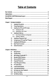
...the motherboard, do not allow screws to come in a high-temperature environment. • Turning on the motherboard, make sure the power supply voltage has been set according to the local voltage standard. • Before using the product, please verify that all cables and...no leftover screws or metal components placed on the motherboard or within an electrostatic shielding container. • Before unplugging the power supply cable from the power outlet before installing or removing the motherboard or other hardware components. • When connecting hardware components to the internal ...
...the motherboard, do not allow screws to come in a high-temperature environment. • Turning on the motherboard, make sure the power supply voltage has been set according to the local voltage standard. • Before using the product, please verify that all cables and...no leftover screws or metal components placed on the motherboard or within an electrostatic shielding container. • Before unplugging the power supply cable from the power outlet before installing or removing the motherboard or other hardware components. • When connecting hardware components to the internal ...
Manual
Page 11
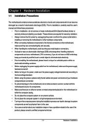
... Out header 1 x IEEE 1394a header 2 x USB 2.0/1.1 headers 1 x serial port header 1 x chassis intrusion header 1 x power LED header Back Panel 1 x PS/2 keyboard port Connectors 1 x PS/2 mouse port 1 x coaxial S/PDIF Out connector 1 x optical ... System voltage detection CPU/System temperature detection CPU/System/Power fan speed detection CPU overheating warning CPU/System/Power fan fail warning CPU/System fan speed control (Note 4) BIOS ...
... Out header 1 x IEEE 1394a header 2 x USB 2.0/1.1 headers 1 x serial port header 1 x chassis intrusion header 1 x power LED header Back Panel 1 x PS/2 keyboard port Connectors 1 x PS/2 mouse port 1 x coaxial S/PDIF Out connector 1 x optical ... System voltage detection CPU/System temperature detection CPU/System/Power fan speed detection CPU overheating warning CPU/System/Power fan fail warning CPU/System fan speed control (Note 4) BIOS ...

Manual
Page 13
... and thin layer of thermal grease on the surface of the CPU. • Do not turn off the computer and unplug the power cord from the power outlet before you wish to set beyond the standard specifications, please do so according to prevent hardware damage. • Locate the pin... one (denoted by a small triangle) of the CPU. mended that the motherboard supports the CPU. (Go to GIGABYTE's website for the peripherals. Locate the...
... and thin layer of thermal grease on the surface of the CPU. • Do not turn off the computer and unplug the power cord from the power outlet before you wish to set beyond the standard specifications, please do so according to prevent hardware damage. • Locate the pin... one (denoted by a small triangle) of the CPU. mended that the motherboard supports the CPU. (Go to GIGABYTE's website for the peripherals. Locate the...
Manual
Page 14
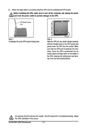
... the middle of the CPU, lowering the locking lever and latching it into the socket. GA-MA790X-UD4P Motherboard - 14 - Before installing the CPU, make sure to turn off the computer and unplug the power cord from the power outlet to prevent damage to correctly install the CPU into the CPU socket. The CPU cannot...
... the middle of the CPU, lowering the locking lever and latching it into the socket. GA-MA790X-UD4P Motherboard - 14 - Before installing the CPU, make sure to turn off the computer and unplug the power cord from the power outlet to prevent damage to correctly install the CPU into the CPU socket. The CPU cannot...
Manual
Page 15
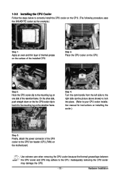
...adhere to the CPU. Step 3: Hook the CPU cooler clip to correctly install the CPU cooler on the CPU. (The following procedure uses the GIGABYTE cooler as the picture above shows) to lock into place. (Refer to your CPU cooler installation manual for instructions on installing the cooler.) Step... 5: Finally, attach the power connector of the CPU cooler to the mounting lug on the retention frame. Step 2: Place the CPU cooler on the CPU. Use extreme care...
...adhere to the CPU. Step 3: Hook the CPU cooler clip to correctly install the CPU cooler on the CPU. (The following procedure uses the GIGABYTE cooler as the picture above shows) to lock into place. (Refer to your CPU cooler installation manual for instructions on installing the cooler.) Step... 5: Finally, attach the power connector of the CPU cooler to the mounting lug on the retention frame. Step 2: Place the CPU cooler on the CPU. Use extreme care...
Manual
Page 16
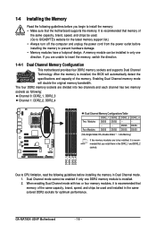
...in the same colored DDR2 sockets for the latest memory support list.) • Always turn off the computer and unplug the power cord from the power outlet before installing the memory to prevent hardware damage. • Memory modules have a foolproof design. DS/SS DS/SS Four...SS (SS=Single-Sided, DS=Double-Sided, "- -"=No Memory) If two memory modules are to be used . (Go to GIGABYTE's website for optimum performance. GA-MA790X-UD4P Motherboard - 16 - Enabling Dual Channel memory mode will automatically detect the specifications and capacity of the same capacity, brand, speed, and...
...in the same colored DDR2 sockets for the latest memory support list.) • Always turn off the computer and unplug the power cord from the power outlet before installing the memory to prevent hardware damage. • Memory modules have a foolproof design. DS/SS DS/SS Four...SS (SS=Single-Sided, DS=Double-Sided, "- -"=No Memory) If two memory modules are to be used . (Go to GIGABYTE's website for optimum performance. GA-MA790X-UD4P Motherboard - 16 - Enabling Dual Channel memory mode will automatically detect the specifications and capacity of the same capacity, brand, speed, and...
Manual
Page 17
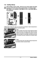
... DIMMs. Be sure to the memory module. 1-4-2 Installing a Memory Before installing a memory module , make sure to turn off the computer and unplug the power cord from the power outlet to prevent damage to install DDR2 DIMMs on this motherboard. Step 2: The clips at both ends of the memory socket. Hardware Installation Spread...
... DIMMs. Be sure to the memory module. 1-4-2 Installing a Memory Before installing a memory module , make sure to turn off the computer and unplug the power cord from the power outlet to prevent damage to install DDR2 DIMMs on this motherboard. Step 2: The clips at both ends of the memory socket. Hardware Installation Spread...

Manual
Page 18
... the chassis cover(s). 6. Make sure the card is securely seated in your expansion card. • Always turn off the computer and unplug the power cord from the slot. GA-MA790X-UD4P Motherboard - 18 - • Removing the Card from the PCIEX8_1 slot: Press the white latch at the end of the card until it is...: Gently push down on the top edge of the PCI Express slot to release the card and then pull the card straight up from the power outlet before you begin to correctly install your card.
... the chassis cover(s). 6. Make sure the card is securely seated in your expansion card. • Always turn off the computer and unplug the power cord from the slot. GA-MA790X-UD4P Motherboard - 18 - • Removing the Card from the PCIEX8_1 slot: Press the white latch at the end of the card until it is...: Gently push down on the top edge of the PCI Express slot to release the card and then pull the card straight up from the power outlet before you begin to correctly install your card.
Manual
Page 19
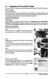
... First under Advanced BIOS Features in BIOS Setup to PEG first. (Start your operating system, access the Catalyst Control Center. C. Hardware Installation The exact power requirements depend on your graphics cards, install the connecting bridges on the two cards. (Note: Procedure for enabling CrossFireX may slightly differ by graphics cards...Display First to PEG. 1-6 Configuring an ATI CrossFireXTM System To enable CrossFireXTM technology, you need two graphics cards that is able to provide sufficient power to fully support an CrossFireX configuration and other components in your system...
... First under Advanced BIOS Features in BIOS Setup to PEG first. (Start your operating system, access the Catalyst Control Center. C. Hardware Installation The exact power requirements depend on your graphics cards, install the connecting bridges on the two cards. (Note: Procedure for enabling CrossFireX may slightly differ by graphics cards...Display First to PEG. 1-6 Configuring an ATI CrossFireXTM System To enable CrossFireXTM technology, you need two graphics cards that is able to provide sufficient power to fully support an CrossFireX configuration and other components in your system...

Manual
Page 20
... by expanding the internal SATA port(s) to the chassis back panel. • Turn off the power of the external enclosure. Then attach the SATA power cable to the power connector on the bracket. Follow the steps below to install the SATA bracket: Step 1: Locate ... damage to hardware. • Insert the SATA signal cable and SATA power cable securely into to the power supply. GA-MA790X-UD4P Motherboard - 20 - SATA Bracket SATA Signal Cable SATA Power Cable External SATA Connector Power Connector External SATA Connector The SATA bracket includes one SATA bracket, one ...
... by expanding the internal SATA port(s) to the chassis back panel. • Turn off the power of the external enclosure. Then attach the SATA power cable to the power connector on the bracket. Follow the steps below to install the SATA bracket: Step 1: Locate ... damage to hardware. • Insert the SATA signal cable and SATA power cable securely into to the power supply. GA-MA790X-UD4P Motherboard - 20 - SATA Bracket SATA Signal Cable SATA Power Cable External SATA Connector Power Connector External SATA Connector The SATA bracket includes one SATA bracket, one ...
Manual
Page 23
Unplug the power cord from the power outlet to prevent damage to the devices. • After installing the device and before connecting external devices: • First make sure your devices are compliant ...
Unplug the power cord from the power outlet to prevent damage to the devices. • After installing the device and before connecting external devices: • First make sure your devices are compliant ...
Manual
Page 24
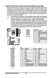
... +5V 18 GND 19 Power Good 20 5V SB(stand by +5V) 21 +12V 22 +12V(Onlyfor2x12-pinATX) 23 3.3V(Onlyfor2x12-pinATX) 24 Definition 3.3V -12V GND PS_ON(soft On/Off) GND GND GND -5V +5V +5V +5V (Only for 2x12-pin ATX) GND (Only for 2x12-pin ATX) GA-MA790X-UD4P Motherboard - 24 -
... +5V 18 GND 19 Power Good 20 5V SB(stand by +5V) 21 +12V 22 +12V(Onlyfor2x12-pinATX) 23 3.3V(Onlyfor2x12-pinATX) 24 Definition 3.3V -12V GND PS_ON(soft On/Off) GND GND GND -5V +5V +5V +5V (Only for 2x12-pin ATX) GND (Only for 2x12-pin ATX) GA-MA790X-UD4P Motherboard - 24 -

Manual
Page 25
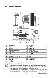
.... 3/4/5) CPU_FAN / SYS_FAN1 / SYS_FAN2 / PWR_FAN (Fan Headers) The motherboard has a 4-pin CPU fan header (CPU_FAN), a 4-pin (SYS_FAN1) and two 3-pin (SYS_FAN2) system fan headers, and a 3-pin power fan header (PWR_FAN). Most fan headers possess a foolproof insertion design. Definition 1 GND 2 +12V 3 Sense • Be sure to connect fan cables to the fan headers...
.... 3/4/5) CPU_FAN / SYS_FAN1 / SYS_FAN2 / PWR_FAN (Fan Headers) The motherboard has a 4-pin CPU fan header (CPU_FAN), a 4-pin (SYS_FAN1) and two 3-pin (SYS_FAN2) system fan headers, and a 3-pin power fan header (PWR_FAN). Most fan headers possess a foolproof insertion design. Definition 1 GND 2 +12V 3 Sense • Be sure to connect fan cables to the fan headers...
Manual
Page 27
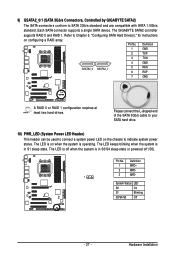
The GIGABYTE SATA2 controller supports RAID 0 and RAID 1. Please connect the L-shaped end of the SATA 3Gb/s cable to your SATA hard drive. 10) PWR_LED (System Power LED Header) This header can be used to connect a system power LED on the chassis to Chapter 5, "Configuring SATA ... Hardware Installation The LED is off when the system is in S3/S4 sleep state or powered off (S5). Each SATA connector supports a single SATA device. 9) GSATA2_0/1 (SATA 3Gb/s Connectors, Controlled by GIGABYTE SATA2) The SATA connectors conform to SATA 3Gb/s standard and are compatible with SATA 1.5Gb...
The GIGABYTE SATA2 controller supports RAID 0 and RAID 1. Please connect the L-shaped end of the SATA 3Gb/s cable to your SATA hard drive. 10) PWR_LED (System Power LED Header) This header can be used to connect a system power LED on the chassis to Chapter 5, "Configuring SATA ... Hardware Installation The LED is off when the system is in S3/S4 sleep state or powered off (S5). Each SATA connector supports a single SATA device. 9) GSATA2_0/1 (SATA 3Gb/s Connectors, Controlled by GIGABYTE SATA2) The SATA connectors conform to SATA 3Gb/s standard and are compatible with SATA 1.5Gb...
Manual
Page 28
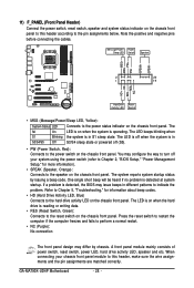
...by chassis. PW+ PWSPEAK+ SPEAK- 2 20 1 19 HD+ HD- RESRES+ NC Hard Drive Activity LED Reset Switch • MSG (Message/Power/Sleep LED, Yellow): System Status LED Connects to this header according to the reset switch on the chassis front panel. The LED is off (...cables. Message/Power/ Power Sleep LED Switch Speaker MSG+ MSG- The LED keeps blinking when S1 Blinking the system is reading or writing data. • RES (Reset Switch, Green): Connects to the pin assignments below. The LED is on when the system is detected at system startup. GA-MA790X-UD4P Motherboard - ...
...by chassis. PW+ PWSPEAK+ SPEAK- 2 20 1 19 HD+ HD- RESRES+ NC Hard Drive Activity LED Reset Switch • MSG (Message/Power/Sleep LED, Yellow): System Status LED Connects to this header according to the reset switch on the chassis front panel. The LED is off (...cables. Message/Power/ Power Sleep LED Switch Speaker MSG+ MSG- The LED keeps blinking when S1 Blinking the system is reading or writing data. • RES (Reset Switch, Green): Connects to the pin assignments below. The LED is on when the system is detected at system startup. GA-MA790X-UD4P Motherboard - ...

Manual
Page 29
Definition 1 MIC2_L Pin No. 1 Definition MIC 2 1 2 GND 3 MIC2_R 2 GND 3 MIC Power 4 -ACZ_DET 4 NC 5 LINE2_R 5 Line Out (R) 6 GND 6 NC 7 FAUDIO_JD 7 NC 8 No Pin 8 No Pin 9 LINE2_L 9 Line Out (L) 10 GND 10 NC • The front panel audio ...
Definition 1 MIC2_L Pin No. 1 Definition MIC 2 1 2 GND 3 MIC2_R 2 GND 3 MIC Power 4 -ACZ_DET 4 NC 5 LINE2_R 5 Line Out (R) 6 GND 6 NC 7 FAUDIO_JD 7 NC 8 No Pin 8 No Pin 9 LINE2_L 9 Line Out (L) 10 GND 10 NC • The front panel audio ...
Manual
Page 30
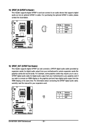
... cards and sound cards. Definition 1 1 Power 2 SPDIFI 3 GND 15) SPDIF_OUT (S/PDIF Out Header) This header supports digital S/PDIF out and connects a S/PDIF digital audio cable (provided by expansion cards) for digital audio output from the HDMI display at the same time. Pin No. Definition 1 SPDIFO 1 2 GND GA-MA790X-UD4P Motherboard - 30 - For example, some...
... cards and sound cards. Definition 1 1 Power 2 SPDIFI 3 GND 15) SPDIF_OUT (S/PDIF Out Header) This header supports digital S/PDIF out and connects a S/PDIF digital audio cable (provided by expansion cards) for digital audio output from the HDMI display at the same time. Pin No. Definition 1 SPDIFO 1 2 GND GA-MA790X-UD4P Motherboard - 30 - For example, some...
Manual
Page 31
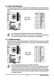
...header conforms to USB 2.0/1.1 specification. Each USB header can provide one end of the device cable to your computer and unplug the power cord from the power outlet to prevent damage to the IEEE 1394a device. Pin No. For purchasing the optional IEEE 1394a bracket, please contact the local... to IEEE 1394a specification. For purchasing the optional USB bracket, please contact the local dealer. 9 1 10 2 Pin No. 1 2 3 4 5 6 7 8 9 10 Definition Power (5V) Power (5V) USB DXUSB DYUSB DX+ USB DY+ GND GND No Pin NC • Do not plug the IEEE 1394 bracket (2x5-pin) cable into the...
...header conforms to USB 2.0/1.1 specification. Each USB header can provide one end of the device cable to your computer and unplug the power cord from the power outlet to prevent damage to the IEEE 1394a device. Pin No. For purchasing the optional IEEE 1394a bracket, please contact the local... to IEEE 1394a specification. For purchasing the optional USB bracket, please contact the local dealer. 9 1 10 2 Pin No. 1 2 3 4 5 6 7 8 9 10 Definition Power (5V) Power (5V) USB DXUSB DYUSB DX+ USB DY+ GND GND No Pin NC • Do not plug the IEEE 1394 bracket (2x5-pin) cable into the...


