Manual
Page 4
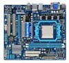
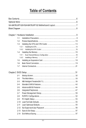
Table of Contents Box Contents...6 Optional Items...6 GA-MA78LMT-S2H/GA-MA78LMT-S2 Motherboard Layout 7 Block Diagram...8 Chapter 1 Hardware Installation 9 1-1 Installation Precautions 9 1-2 Product Specifications 10 1-3 Installing the CPU and CPU Cooler 13 1-3-1 Installing the CPU 13 1-3-2 Installing the CPU Cooler 15 1-4 Installing the Memory 16 1-4-1 Dual Channel Memory Configuration 16 1-4-2 Installing a Memory 17 1-5 Installing an Expansion Card 18 1-6 Back Panel...
Table of Contents Box Contents...6 Optional Items...6 GA-MA78LMT-S2H/GA-MA78LMT-S2 Motherboard Layout 7 Block Diagram...8 Chapter 1 Hardware Installation 9 1-1 Installation Precautions 9 1-2 Product Specifications 10 1-3 Installing the CPU and CPU Cooler 13 1-3-1 Installing the CPU 13 1-3-2 Installing the CPU Cooler 15 1-4 Installing the Memory 16 1-4-1 Dual Channel Memory Configuration 16 1-4-2 Installing a Memory 17 1-5 Installing an Expansion Card 18 1-6 Back Panel...
Manual
Page 8
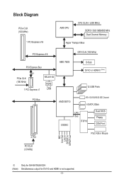
Block Diagram PCIe CLK (100 MHz) 1 PCI Express x16 AM3 CPU CPU CLK+/- (200 MHz) DDR3 1333/1066/800 MHz Dual Channel Memory Hyper Transport Bus PCI Express x16 GFX CLK (100 MHz) PCI Express Bus x1 ... BIOS Floppy COM Port MIC Line Out Line In S/PDIF In S/PDIF Out 2 PCI PS/2 KB or Mouse PCI CLK (33 MHz) j (Note) Only for GA-MA78LM-S2H Simultaneous output for DVI-D and HDMI is not supported. - 8 -
Block Diagram PCIe CLK (100 MHz) 1 PCI Express x16 AM3 CPU CPU CLK+/- (200 MHz) DDR3 1333/1066/800 MHz Dual Channel Memory Hyper Transport Bus PCI Express x16 GFX CLK (100 MHz) PCI Express Bus x1 ... BIOS Floppy COM Port MIC Line Out Line In S/PDIF In S/PDIF Out 2 PCI PS/2 KB or Mouse PCI CLK (33 MHz) j (Note) Only for GA-MA78LM-S2H Simultaneous output for DVI-D and HDMI is not supported. - 8 -
Manual
Page 9
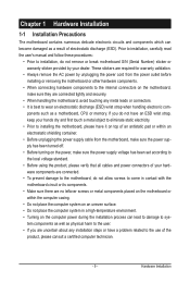
... other hardware components. • When connecting hardware components to the internal connectors on the computer power during the installation process can become damaged as a motherboard, CPU or memory. Prior to installation, carefully read the user's manual and follow these procedures: • Prior to installation, do not remove or break motherboard S/N (Serial...
... other hardware components. • When connecting hardware components to the internal connectors on the computer power during the installation process can become damaged as a motherboard, CPU or memory. Prior to installation, carefully read the user's manual and follow these procedures: • Prior to installation, do not remove or break motherboard S/N (Serial...
Manual
Page 10
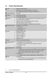
... for AM3 processors: AMD Phenom™ II processor/ AMD Athlon™ II processor (Go to GIGABYTE's website for the latest CPU support list.) Hyper Transport Bus 5200 MT/s Chipset Memory Onboard Graphics Audio North... South Bridge: - Up to 12 USB 2.0/1.1 ports (8 on the back panel, 4 via the USB brackets connected to 4 SATA 3Gb/s devices - Support for GA-MA78LMT-S2H Hardware Installation - 10 -
... for AM3 processors: AMD Phenom™ II processor/ AMD Athlon™ II processor (Go to GIGABYTE's website for the latest CPU support list.) Hyper Transport Bus 5200 MT/s Chipset Memory Onboard Graphics Audio North... South Bridge: - Up to 12 USB 2.0/1.1 ports (8 on the back panel, 4 via the USB brackets connected to 4 SATA 3Gb/s devices - Support for GA-MA78LMT-S2H Hardware Installation - 10 -
Manual
Page 11
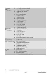
...pin ATX main power connector w 1 x 4-pin ATX 12V power connector w 1 x floppy disk drive connector w 1 x IDE connector w 4 x SATA 3Gb/s connectors w 1 x CPU fan header w 1 x system fan header w 1 x front panel header w 1 x front panel audio header w 1 x CD In connector w 1 x S/PDIF In/Out header... detection CPU/System temperature detection CPU/System fan speed detection CPU overheating warning CPU/System fan fail warning CPU fan speed control (Note 5) 2 x 8 Mbit flash Use of licensed AWARD BIOS Support for DualBIOS™ PnP 1.0a, DMI 2.0, SM BIOS 2.4, ACPI 1.0b j Only for GA-MA78LMT-S2H ...
...pin ATX main power connector w 1 x 4-pin ATX 12V power connector w 1 x floppy disk drive connector w 1 x IDE connector w 4 x SATA 3Gb/s connectors w 1 x CPU fan header w 1 x system fan header w 1 x front panel header w 1 x front panel audio header w 1 x CD In connector w 1 x S/PDIF In/Out header... detection CPU/System temperature detection CPU/System fan speed detection CPU overheating warning CPU/System fan fail warning CPU fan speed control (Note 5) 2 x 8 Mbit flash Use of licensed AWARD BIOS Support for DualBIOS™ PnP 1.0a, DMI 2.0, SM BIOS 2.4, ACPI 1.0b j Only for GA-MA78LMT-S2H ...
Manual
Page 12
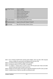
... audio, you have to use an HD front panel audio module and enable themulti-channel audio feature through the audio driver. (Note 5) Whether the CPU fan speed control function is supported will depend on the CPU cooler you install. (Note 6) Available functions in EasyTune may differ by motherboard model. Hardware Installation - 12 -
... audio, you have to use an HD front panel audio module and enable themulti-channel audio feature through the audio driver. (Note 5) Whether the CPU fan speed control function is supported will depend on the CPU cooler you install. (Note 6) Available functions in EasyTune may differ by motherboard model. Hardware Installation - 12 -
Manual
Page 13
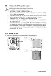
...Make sure that the system bus frequency be set the frequency beyond hardware specifications since it does not meet the standard requirements for the latest CPU support list.) • Always turn off the computer and unplug the power cord from the power outlet before you wish to set beyond...both sides of the CPU and alignment keys on the CPU socket.) • Apply an even and thin layer of thermal grease on the surface of the CPU. • Do not turn on the computer if the CPU cooler is not recommended that the motherboard supports the CPU. (Go to GIGABYTE's website for the peripherals...
...Make sure that the system bus frequency be set the frequency beyond hardware specifications since it does not meet the standard requirements for the latest CPU support list.) • Always turn off the computer and unplug the power cord from the power outlet before you wish to set beyond...both sides of the CPU and alignment keys on the CPU socket.) • Apply an even and thin layer of thermal grease on the surface of the CPU. • Do not turn on the computer if the CPU cooler is not recommended that the motherboard supports the CPU. (Go to GIGABYTE's website for the peripherals...
Manual
Page 14
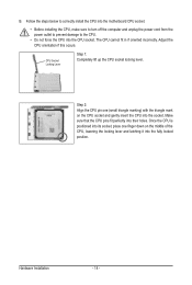
... the CPU pin one finger down on the CPU socket and gently insert the CPU into the fully locked position. Hardware Installation - 14 - CPU Socket Locking Lever Step 1: Completely lift up the CPU socket locking lever. Make sure that the CPU pins fit perfectly into the CPU socket. B. Once the CPU is ... with the triangle mark on the middle of the CPU, lowering the locking lever and latching it into the socket. Follow the steps below to correctly install the CPU into the motherboard CPU socket. • Before installing the CPU, make sure to turn off the computer and unplug...
... the CPU pin one finger down on the CPU socket and gently insert the CPU into the fully locked position. Hardware Installation - 14 - CPU Socket Locking Lever Step 1: Completely lift up the CPU socket locking lever. Make sure that the CPU pins fit perfectly into the CPU socket. B. Once the CPU is ... with the triangle mark on the middle of the CPU, lowering the locking lever and latching it into the socket. Follow the steps below to correctly install the CPU into the motherboard CPU socket. • Before installing the CPU, make sure to turn off the computer and unplug...
Manual
Page 15
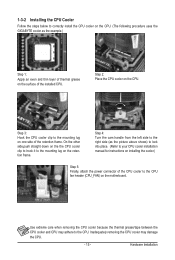
... manual for instructions on installing the cooler.) Step 5: Finally, attach the power connector of the CPU cooler to correctly install the CPU cooler on the CPU. (The following procedure uses the GIGABYTE cooler as the example.) Step 1: Apply an even and thin layer of thermal grease on the... surface of the retention frame. 1-3-2 Installing the CPU Cooler Follow the steps below to the CPU fan header (CPU_FAN) ...
... manual for instructions on installing the cooler.) Step 5: Finally, attach the power connector of the CPU cooler to correctly install the CPU cooler on the CPU. (The following procedure uses the GIGABYTE cooler as the example.) Step 1: Apply an even and thin layer of thermal grease on the... surface of the retention frame. 1-3-2 Installing the CPU Cooler Follow the steps below to the CPU fan header (CPU_FAN) ...
Manual
Page 16
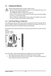
...sockets are divided into two channels and each channel has one memory socket as following: Channel 0: DDR3_1 Channel 1: DDR3_2 DDR3_1 DDR3_2 Due to CPU limitation, read the following guidelines before you are unable to insert the memory, switch the direction. 1-4-1 Dual Channel Memory Configuration This motherboard ...enabled if only one direction. It is recommended that memory of the same capacity, brand, speed, and chips be used . (Go to GIGABYTE's website for the latest memory support list.) • Always turn off the computer and unplug the power cord from the power outlet before ...
...sockets are divided into two channels and each channel has one memory socket as following: Channel 0: DDR3_1 Channel 1: DDR3_2 DDR3_1 DDR3_2 Due to CPU limitation, read the following guidelines before you are unable to insert the memory, switch the direction. 1-4-1 Dual Channel Memory Configuration This motherboard ...enabled if only one direction. It is recommended that memory of the same capacity, brand, speed, and chips be used . (Go to GIGABYTE's website for the latest memory support list.) • Always turn off the computer and unplug the power cord from the power outlet before ...
Manual
Page 20
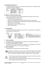
... themulti-channel audio feature through the audio driver. Dual Display Configurations: This motherboard provides three ports for a headphone or 2-channel speaker. A. The table below . • CPU: AMD Phenom™ X3 processor or above • Memory: Two 1 GB DDR3 1066 MHz memory modules with dual channel mode enabled • BIOS Setup: At...
... themulti-channel audio feature through the audio driver. Dual Display Configurations: This motherboard provides three ports for a headphone or 2-channel speaker. A. The table below . • CPU: AMD Phenom™ X3 processor or above • Memory: Two 1 GB DDR3 1066 MHz memory modules with dual channel mode enabled • BIOS Setup: At...
Manual
Page 22
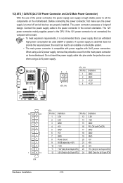
Connect the power supply cable to the CPU. 1/2) ATX_12V/ATX (2x2 12V Power Connector and 2x12 Main Power Connector) With the use of the power connector, the power supply can supply enough stable ...
Connect the power supply cable to the CPU. 1/2) ATX_12V/ATX (2x2 12V Power Connector and 2x12 Main Power Connector) With the use of the power connector, the power supply can supply enough stable ...
Manual
Page 23
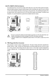
...is typically designated by a stripe of different color. The pin 1 of the connector and the floppy disk drive cable. The motherboard supports CPU fan speed control, which requires the use of floppy disk drives supported are not configuration jumper blocks. Overheating may hang. • These...system fan be sure to connect it in damage to connect a floppy disk drive. The types of a CPU fan with fan speed control design. 3/4) CPU_FAN/SYS_FAN (Fan Headers) The motherboard has a 4-pin CPU fan header (CPU_FAN) and a 3-pin (SYS_FAN) system fan headers. Before connecting a floppy disk drive,...
...is typically designated by a stripe of different color. The pin 1 of the connector and the floppy disk drive cable. The motherboard supports CPU fan speed control, which requires the use of floppy disk drives supported are not configuration jumper blocks. Overheating may hang. • These...system fan be sure to connect it in damage to connect a floppy disk drive. The types of a CPU fan with fan speed control design. 3/4) CPU_FAN/SYS_FAN (Fan Headers) The motherboard has a 4-pin CPU fan header (CPU_FAN) and a 3-pin (SYS_FAN) system fan headers. Before connecting a floppy disk drive,...

Manual
Page 33
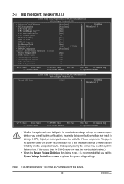
... by BIOS version. - 33 - Use arrow keys to move among the items and press to accept or enter a sub-menu. (Sample BIOS Version: GA-MA78LMT-S2H F1b) CMOS Setup Utility-Copyright (C) 1984-2009 Award Software MB Intelligent Tweaker(M.I.T.) Standard CMOS Features Advanced BIOS Features ...Saving ESC: Quit F8: Q-Flash Select Item F10: Save & Exit Setup F11: Save CMOS to BIOS F12: Load CMOS from BIOS Change CPU's Clock & Voltage BIOS Setup Program Function Keys Move the selection bar to select an item Execute command or enter the submenu Main Menu: ...
... by BIOS version. - 33 - Use arrow keys to move among the items and press to accept or enter a sub-menu. (Sample BIOS Version: GA-MA78LMT-S2H F1b) CMOS Setup Utility-Copyright (C) 1984-2009 Award Software MB Intelligent Tweaker(M.I.T.) Standard CMOS Features Advanced BIOS Features ...Saving ESC: Quit F8: Q-Flash Select Item F10: Save & Exit Setup F11: Save CMOS to BIOS F12: Load CMOS from BIOS Change CPU's Clock & Voltage BIOS Setup Program Function Keys Move the selection bar to select an item Execute command or enter the submenu Main Menu: ...
Manual
Page 34
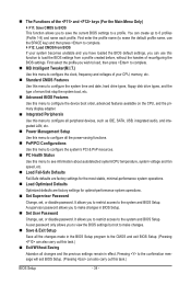
...errors that stop the system boot, etc. Advanced BIOS Features Use this menu to configure the device boot order, advanced features available on the CPU, and the primary display adapter. Integrated Peripherals Use this menu to configure all peripheral devices, such as IDE, SATA, USB, integrated audio...message will exit BIOS Setup. (Pressing can use the SPACE key) and then press to complete. F12: Load CMOS from BIOS If your CPU, memory, etc. Standard CMOS Features Use this menu to configure the system time and date, hard drive types, floppy disk drive types,...
...errors that stop the system boot, etc. Advanced BIOS Features Use this menu to configure the device boot order, advanced features available on the CPU, and the primary display adapter. Integrated Peripherals Use this menu to configure all peripheral devices, such as IDE, SATA, USB, integrated audio...message will exit BIOS Setup. (Pressing can use the SPACE key) and then press to complete. F12: Load CMOS from BIOS If your CPU, memory, etc. Standard CMOS Features Use this menu to configure the system time and date, hard drive types, floppy disk drive types,...
Manual
Page 35
... (C) 1984-2009 Award Software MB Intelligent Tweaker(M.I.T.) } Advanced Clock Calibration } IGX Configuration CPU Clock Ratio CPU NorthBridge Freq.(Note) CPU Host Clock Control x CPU Frequency(MHz) PCIE Clock(MHz) HT Link Width HT Link Frequency Set Memory Clock x... Configuration ******** System Voltage Optimized ******** System Voltage Control x DDR3 Voltage Control x NorthBridge Volt Control x SouthBridge Volt Control x CPU NB VID Control x CPU Voltage Control [Press Enter] [Press Enter] [Auto] [Auto] [Auto] 200 [Auto] [Auto] [Auto] [Auto...
... (C) 1984-2009 Award Software MB Intelligent Tweaker(M.I.T.) } Advanced Clock Calibration } IGX Configuration CPU Clock Ratio CPU NorthBridge Freq.(Note) CPU Host Clock Control x CPU Frequency(MHz) PCIE Clock(MHz) HT Link Width HT Link Frequency Set Memory Clock x... Configuration ******** System Voltage Optimized ******** System Voltage Control x DDR3 Voltage Control x NorthBridge Volt Control x SouthBridge Volt Control x CPU NB VID Control x CPU Voltage Control [Press Enter] [Press Enter] [Auto] [Auto] [Auto] 200 [Auto] [Auto] [Auto] [Auto...

Manual
Page 36
...EC Firmware Selection Advanced Clock Calibration x Value (All Cores) x Value (Core 0) x Value (Core 1) x Value (Core 2) x Value (Core 3) CPU core Control x CPU Core 2 x CPU Core 3 (Note) [Normal] [Disabled] -2% -2% -2% -2% -2% [Auto] Enabled Enabled Item Help Menu Level Move Enter: Select F5...the specific AMD EC firmware version. Per Core Individually configures Advanced Clock Calibration for all CPU cores (number of cores available depends on the CPU being used). After the selection, select Save & Exit Setup in the BIOS Main ...
...EC Firmware Selection Advanced Clock Calibration x Value (All Cores) x Value (Core 0) x Value (Core 1) x Value (Core 2) x Value (Core 3) CPU core Control x CPU Core 2 x CPU Core 3 (Note) [Normal] [Disabled] -2% -2% -2% -2% -2% [Auto] Enabled Enabled Item Help Menu Level Move Enter: Select F5...the specific AMD EC firmware version. Per Core Individually configures Advanced Clock Calibration for all CPU cores (number of cores available depends on the CPU being used). After the selection, select Save & Exit Setup in the BIOS Main ...
Manual
Page 37
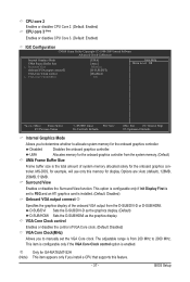
troller. j Only for GA-MA78LMT-S2H (Note) This item appears only if you install a CPU that supports this memory for example, will use only this feature. - 37 - Disabled Disables the onboard graphics controller. MS-DOS, for display. ... graphics card is set the VGA Core clock. BIOS Setup Options are: Auto (default), 128MB, 256MB, 512MB. CPU core 2 Enables or disables CPU Core 2. (Default: Enabled) CPU core 3 (Note) Enables or disables CPU Core 3. (Default: Enabled) IGX Configuration CMOS Setup Utility-Copyright (C) 1984-2009 Award Software Advanced Clock Calibration Internal ...
troller. j Only for GA-MA78LMT-S2H (Note) This item appears only if you install a CPU that supports this memory for example, will use only this feature. - 37 - Disabled Disables the onboard graphics controller. MS-DOS, for display. ... graphics card is set the VGA Core clock. BIOS Setup Options are: Auto (default), 128MB, 256MB, 512MB. CPU core 2 Enables or disables CPU Core 2. (Default: Enabled) CPU core 3 (Note) Enables or disables CPU Core 3. (Default: Enabled) IGX Configuration CMOS Setup Utility-Copyright (C) 1984-2009 Award Software Advanced Clock Calibration Internal ...
Manual
Page 38
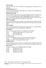
... HT Link Frequency. (Default) 200 MHz~2.6 GHz Sets HT Link Frequency to alter the North Bridge controller frequency for the HT Link between the CPU and chipset. Auto lets BIOS automatically set to X4.00. Sets Memory Clock to manually set the PCIe clock frequency. BIOS Setup - 38 -... for automated system reboot, or clear the CMOS values to reset the board to manually set the width for the installed CPU. PCIE Clock(MHz) Allows you to default values. CPU NorthBridge Freq. (Note) Allows you to 200 MHz~2.6 GHz. Auto BIOS will automatically adjust the HT Link Width. (...
... HT Link Frequency. (Default) 200 MHz~2.6 GHz Sets HT Link Frequency to alter the North Bridge controller frequency for the HT Link between the CPU and chipset. Auto lets BIOS automatically set to X4.00. Sets Memory Clock to manually set the PCIe clock frequency. BIOS Setup - 38 -... for automated system reboot, or clear the CMOS values to reset the board to manually set the width for the installed CPU. PCIE Clock(MHz) Allows you to default values. CPU NorthBridge Freq. (Note) Allows you to 200 MHz~2.6 GHz. Auto BIOS will automatically adjust the HT Link Width. (...
Manual
Page 39
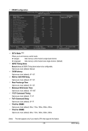
...: Previous Values +/-/PU/PD: Value F10: Save F6: Fail-Safe Defaults ESC: Exit F1: General Help F7: Optimized Defaults DCTs Mode (Note) Allows you install a CPU that supports this feature. - 39 - Row Precharge Time Options are : Auto (default), 90ns, 110ns, 160ns, 300ns, 350ns.
...: Previous Values +/-/PU/PD: Value F10: Save F6: Fail-Safe Defaults ESC: Exit F1: General Help F7: Optimized Defaults DCTs Mode (Note) Allows you install a CPU that supports this feature. - 39 - Row Precharge Time Options are : Auto (default), 90ns, 110ns, 160ns, 300ns, 350ns.


