Manual
Page 1
GA-MA78LM-S2H/ GA-MA78LM-S2 AM2+/AM2 socket motherboard for AMD Phenom™ II processor/ AMD Phenom™ processor/ AMD Athlon™ II processor/ AMD Athlon™ processor/ AMD Sempron™ processor User's Manual Rev. 1001 12ME-MA78L2H-1001R
GA-MA78LM-S2H/ GA-MA78LM-S2 AM2+/AM2 socket motherboard for AMD Phenom™ II processor/ AMD Phenom™ processor/ AMD Athlon™ II processor/ AMD Athlon™ processor/ AMD Sempron™ processor User's Manual Rev. 1001 12ME-MA78L2H-1001R

Manual
Page 3
... be reproduced, copied, translated, transmitted, or published in this product, GIGABYTE provides the following types of the motherboard is 1.0. Changes to use GIGABYTE's unique features, read or download the information on/from the Support&Downloads\Motherboard\Technology Guide page on your motherboard revision before updating motherboard BIOS, drivers, or when looking for technical information. Documentation Classifications...
... be reproduced, copied, translated, transmitted, or published in this product, GIGABYTE provides the following types of the motherboard is 1.0. Changes to use GIGABYTE's unique features, read or download the information on/from the Support&Downloads\Motherboard\Technology Guide page on your motherboard revision before updating motherboard BIOS, drivers, or when looking for technical information. Documentation Classifications...

Manual
Page 4
Table of Contents Box Contents...6 Optional Items...6 GA-MA78LM-S2H/GA-MA78LM-S2 Motherboard Layout 7 Block Diagram...8 Chapter 1 Hardware Installation 9 1-1 Installation Precautions 9 1-2 Product Specifications 10 1-3 Installing the CPU and CPU Cooler 13 1-3-1 Installing the CPU 13 1-3-2 Installing the CPU ...
Table of Contents Box Contents...6 Optional Items...6 GA-MA78LM-S2H/GA-MA78LM-S2 Motherboard Layout 7 Block Diagram...8 Chapter 1 Hardware Installation 9 1-1 Installation Precautions 9 1-2 Product Specifications 10 1-3 Installing the CPU and CPU Cooler 13 1-3-1 Installing the CPU 13 1-3-2 Installing the CPU ...

Manual
Page 6
... power cable (Part No. 12CF1-2SERPW-0*R) S/PDIF In and Out cable (Part No. 12CR1-1SPINO-1*R) COM port cable (Part No. 12CF1-1CM001-3*R) - 6 - Box Contents GA-MA78LM-S2H or GA-MA78LM-S2 motherboard Motherboard driver disk User's Manual One IDE cable SATA 3Gb/s cables I/O Shield • The box contents above are subject to change without notice. • The...
... power cable (Part No. 12CF1-2SERPW-0*R) S/PDIF In and Out cable (Part No. 12CR1-1SPINO-1*R) COM port cable (Part No. 12CF1-1CM001-3*R) - 6 - Box Contents GA-MA78LM-S2H or GA-MA78LM-S2 motherboard Motherboard driver disk User's Manual One IDE cable SATA 3Gb/s cables I/O Shield • The box contents above are subject to change without notice. • The...

Manual
Page 7
GA-MA78LM-S2H/GA-MA78LM-S2 Motherboard Layout DVI VGA KB(Note)_USB ATX_12V CPU_FAN Socket AM2 M_BIOS B_BIOS ATX IT8718 HDMIj R_USB USB IDE FDD LAN AUDIO F_AUDIO PCIEX1 AMD 760G DDR2_1 DDR2_2 PCIEX16 RTL8111D PCI1 GA-MA78LM-S2H/GA-MA78LM-S2 CD_IN CODEC PCI2 BAT AMD SB710 SATA2_0 COM SATA2_3 SATA2_2 SATA2_1 F_PANEL SPDIF_IO SYS_FAN CLR_CMOS F_USB2 F_USB1 j Only for GA-MA78LM-S2H (Note) Use this port to connect a PS/2 keyboard or PS/2 mouse. - 7 -
GA-MA78LM-S2H/GA-MA78LM-S2 Motherboard Layout DVI VGA KB(Note)_USB ATX_12V CPU_FAN Socket AM2 M_BIOS B_BIOS ATX IT8718 HDMIj R_USB USB IDE FDD LAN AUDIO F_AUDIO PCIEX1 AMD 760G DDR2_1 DDR2_2 PCIEX16 RTL8111D PCI1 GA-MA78LM-S2H/GA-MA78LM-S2 CD_IN CODEC PCI2 BAT AMD SB710 SATA2_0 COM SATA2_3 SATA2_2 SATA2_1 F_PANEL SPDIF_IO SYS_FAN CLR_CMOS F_USB2 F_USB1 j Only for GA-MA78LM-S2H (Note) Use this port to connect a PS/2 keyboard or PS/2 mouse. - 7 -

Manual
Page 9
... the user's manual and follow these procedures: • Prior to installation, do not remove or break motherboard S/N (Serial Number) sticker or warranty sticker provided by unplugging the power cord from the motherboard, make sure the power supply has been turned off. • Before turning on the power, make ...sure they are connected tightly and securely. • When handling the motherboard, avoid touching any installation steps or have it on top of an antistatic pad or within the computer casing. • Do not place the...
... the user's manual and follow these procedures: • Prior to installation, do not remove or break motherboard S/N (Serial Number) sticker or warranty sticker provided by unplugging the power cord from the motherboard, make sure the power supply has been turned off. • Before turning on the power, make ...sure they are connected tightly and securely. • When handling the motherboard, avoid touching any installation steps or have it on top of an antistatic pad or within the computer casing. • Do not place the...
Manual
Page 12
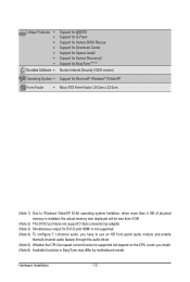
... 5) Whether the CPU fan speed control function is supported will depend on the CPU cooler you install. (Note 6) Available functions in EasyTune may differ by motherboard model.
... 5) Whether the CPU fan speed control function is supported will depend on the CPU cooler you install. (Note 6) Available functions in EasyTune may differ by motherboard model.

Manual
Page 13
... CPU specifications. Locate the pin one of the CPU. • Do not turn on the computer if the CPU cooler is not recommended that the motherboard supports the CPU. (Go to GIGABYTE's website for the peripherals. Hardware Installation
... CPU specifications. Locate the pin one of the CPU. • Do not turn on the computer if the CPU cooler is not recommended that the motherboard supports the CPU. (Go to GIGABYTE's website for the peripherals. Hardware Installation

Manual
Page 14
... on the CPU socket and gently insert the CPU into the fully locked position. Follow the steps below to correctly install the CPU into the motherboard CPU socket. • Before installing the CPU, make sure to turn off the computer and unplug the power cord from the power outlet to prevent...
... on the CPU socket and gently insert the CPU into the fully locked position. Follow the steps below to correctly install the CPU into the motherboard CPU socket. • Before installing the CPU, make sure to turn off the computer and unplug the power cord from the power outlet to prevent...

Manual
Page 15
.... 1-3-2 Installing the CPU Cooler Follow the steps below to correctly install the CPU cooler on the CPU. (The following procedure uses the GIGABYTE cooler as the picture above shows) to lock into place. (Refer to your CPU cooler installation manual for instructions on installing the cooler.)... Step 5: Finally, attach the power connector of the CPU cooler to the CPU fan header (CPU_FAN) on the motherboard. Step 2: Place the CPU cooler on the retention frame. Inadequately removing the CPU cooler may adhere to the right side (as the example.)...
.... 1-3-2 Installing the CPU Cooler Follow the steps below to correctly install the CPU cooler on the CPU. (The following procedure uses the GIGABYTE cooler as the picture above shows) to lock into place. (Refer to your CPU cooler installation manual for instructions on installing the cooler.)... Step 5: Finally, attach the power connector of the CPU cooler to the CPU fan header (CPU_FAN) on the motherboard. Step 2: Place the CPU cooler on the retention frame. Inadequately removing the CPU cooler may adhere to the right side (as the example.)...

Manual
Page 16
...have a foolproof design. The two DDR2 memory sockets are unable to insert the memory, switch the direction. 1-4-1 Dual Channel Memory Configuration This motherboard provides two DDR2 memory sockets and supports Dual Channel Technology. When enabling Dual Channel mode with two memory modules, it is recommended that memory ...of the same capacity, brand, speed, and chips be used . (Go to GIGABYTE's website for the latest memory support list.) • Always turn off the computer and unplug the power cord from the power outlet before...
...have a foolproof design. The two DDR2 memory sockets are unable to insert the memory, switch the direction. 1-4-1 Dual Channel Memory Configuration This motherboard provides two DDR2 memory sockets and supports Dual Channel Technology. When enabling Dual Channel mode with two memory modules, it is recommended that memory ...of the same capacity, brand, speed, and chips be used . (Go to GIGABYTE's website for the latest memory support list.) • Always turn off the computer and unplug the power cord from the power outlet before...

Manual
Page 17
Follow the steps below to the memory module. Spread the retaining clips at both ends of the memory module. Place the memory module on this motherboard. 1-4-2 Installing a Memory Before installing a memory module , make sure to turn off the computer and unplug the power cord from the power outlet to prevent damage ...
Follow the steps below to the memory module. Spread the retaining clips at both ends of the memory module. Place the memory module on this motherboard. 1-4-2 Installing a Memory Before installing a memory module , make sure to turn off the computer and unplug the power cord from the power outlet to prevent damage ...

Manual
Page 18
... your computer. PCI Express x1 Slot PCI Express x16 Slot PCI Slot Follow the steps below to install an expansion card: • Make sure the motherboard supports the expansion card. Make sure the metal contacts on the top edge of the card until it is fully inserted into the slot. 4.
... your computer. PCI Express x1 Slot PCI Express x16 Slot PCI Slot Follow the steps below to install an expansion card: • Make sure the motherboard supports the expansion card. Make sure the metal contacts on the top edge of the card until it is fully inserted into the slot. 4.

Manual
Page 20
... No data transmission or receiving is occurring Line In Jack (Blue) The default line in jack. Do not rock it straight out from the motherboard. • When removing the cable, pull it side to side to connect front speakers in devices such as an optical drive, walkman, etc... used to prevent an electrical short inside the cable connector. Refer to the instructions on setting up to this jack. Dual Display Configurations: This motherboard provides three ports for line in a 4/5.1-channel audio configuration. Playback of HD DVD and Blu-ray Discs: In order to get better playback ...
... No data transmission or receiving is occurring Line In Jack (Blue) The default line in jack. Do not rock it straight out from the motherboard. • When removing the cable, pull it side to side to connect front speakers in devices such as an optical drive, walkman, etc... used to prevent an electrical short inside the cable connector. Refer to the instructions on setting up to this jack. Dual Display Configurations: This motherboard provides three ports for line in a 4/5.1-channel audio configuration. Playback of HD DVD and Blu-ray Discs: In order to get better playback ...

Manual
Page 21
..., make sure your devices are compliant with the connectors you wish to connect. • Before installing the devices, be sure to the connector on the motherboard. - 21 - Unplug the power cord from the power outlet to prevent damage to the devices. • After installing the device and before connecting external devices...
..., make sure your devices are compliant with the connectors you wish to connect. • Before installing the devices, be sure to the connector on the motherboard. - 21 - Unplug the power cord from the power outlet to prevent damage to the devices. • After installing the device and before connecting external devices...

Manual
Page 22
... the result can withstand high power consumption be used (500W or greater). If a power supply is turned off and all the components on the motherboard. The power connector possesses a foolproof design. Connect the power supply cable to the CPU. When using a 2x10 power supply. 31 42 ATX_12V ...supply cable into pins under the protective cover when using a 2x12 power supply, remove the protective cover from the main power connector on the motherboard. 1/2) ATX_12V/ATX (2x2 12V Power Connector and 2x12 Main Power Connector) With the use of the power connector, the power supply can...
... the result can withstand high power consumption be used (500W or greater). If a power supply is turned off and all the components on the motherboard. The power connector possesses a foolproof design. Connect the power supply cable to the CPU. When using a 2x10 power supply. 31 42 ATX_12V ...supply cable into pins under the protective cover when using a 2x12 power supply, remove the protective cover from the main power connector on the motherboard. 1/2) ATX_12V/ATX (2x2 12V Power Connector and 2x12 Main Power Connector) With the use of the power connector, the power supply can...

Manual
Page 23
... Installation For purchasing the optional floppy disk drive cable, please contact the local dealer. 34 33 2 1 - 23 - 3/4) CPU_FAN/SYS_FAN (Fan Headers) The motherboard has a 4-pin CPU fan header (CPU_FAN) and a 3-pin (SYS_FAN) system fan headers. Do not place a jumper cap on the headers. 5) FDD ...2 3 Definition GND +12V Sense • Be sure to connect fan cables to the fan headers to connect a floppy disk drive. The motherboard supports CPU fan speed control, which requires the use of different color. For optimum heat dissipation, it in damage to locate pin 1 of ...
... Installation For purchasing the optional floppy disk drive cable, please contact the local dealer. 34 33 2 1 - 23 - 3/4) CPU_FAN/SYS_FAN (Fan Headers) The motherboard has a 4-pin CPU fan header (CPU_FAN) and a 3-pin (SYS_FAN) system fan headers. Do not place a jumper cap on the headers. 5) FDD ...2 3 Definition GND +12V Sense • Be sure to connect fan cables to the fan headers to connect a floppy disk drive. The motherboard supports CPU fan speed control, which requires the use of different color. For optimum heat dissipation, it in damage to locate pin 1 of ...

Manual
Page 26
Incorrect connection between the module connector and the motherboard header will be present on both of the motherboard header. If your chassis provides an AC'97 front panel audio module, refer to this header. Pin No. For HD Front Panel Audio: For AC'...
Incorrect connection between the module connector and the motherboard header will be present on both of the motherboard header. If your chassis provides an AC'97 front panel audio module, refer to this header. Pin No. For HD Front Panel Audio: For AC'...

Manual
Page 28
... the two pins or use a metal object like a screwdriver to Chapter 2, "BIOS Setup," for a few seconds. Failure to do so may cause damage to the motherboard. • After system restart, go to BIOS Setup to load factory defaults (select Load Optimized Defaults) or manually configure the BIOS settings (refer to touch...
... the two pins or use a metal object like a screwdriver to Chapter 2, "BIOS Setup," for a few seconds. Failure to do so may cause damage to the motherboard. • After system restart, go to BIOS Setup to load factory defaults (select Load Optimized Defaults) or manually configure the BIOS settings (refer to touch...
Manual
Page 31
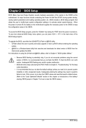
... POST when the power is recommended that you need to) to prevent system instability or other unexpected results. To upgrade the BIOS, use either the GIGABYTE Q-Flash or @BIOS utility. • Q-Flash allows the user to quickly and easily upgrade or back up BIOS without entering the operating system. •...'s failure to boot. Chapter 2 BIOS Setup BIOS (Basic Input and Output System) records hardware parameters of the system in the CMOS on the motherboard supplies the necessary power to the CMOS to keep the configuration values in the CMOS. When the power is turned off, the battery on the...
... POST when the power is recommended that you need to) to prevent system instability or other unexpected results. To upgrade the BIOS, use either the GIGABYTE Q-Flash or @BIOS utility. • Q-Flash allows the user to quickly and easily upgrade or back up BIOS without entering the operating system. •...'s failure to boot. Chapter 2 BIOS Setup BIOS (Basic Input and Output System) records hardware parameters of the system in the CMOS on the motherboard supplies the necessary power to the CMOS to keep the configuration values in the CMOS. When the power is turned off, the battery on the...


