Manual
Page 1
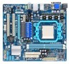
GA-MA78LM-S2H/ GA-MA78LM-S2 AM2+/AM2 socket motherboard for AMD Phenom™ II processor/ AMD Phenom™ processor/ AMD Athlon™ II processor/ AMD Athlon™ processor/ AMD Sempron™ processor User's Manual Rev. 1001 12ME-MA78L2H-1001R
GA-MA78LM-S2H/ GA-MA78LM-S2 AM2+/AM2 socket motherboard for AMD Phenom™ II processor/ AMD Phenom™ processor/ AMD Athlon™ II processor/ AMD Athlon™ processor/ AMD Sempron™ processor User's Manual Rev. 1001 12ME-MA78L2H-1001R

Manual
Page 3
... Guide page on your motherboard revision before updating motherboard BIOS, drivers, or when looking for technical information. Changes to use of this manual may be reproduced, copied, translated, transmitted, or published in this manual is protected by GIGABYTE without GIGABYTE's prior written permission. No part of this manual are legally registered to their respective owners.
... Guide page on your motherboard revision before updating motherboard BIOS, drivers, or when looking for technical information. Changes to use of this manual may be reproduced, copied, translated, transmitted, or published in this manual is protected by GIGABYTE without GIGABYTE's prior written permission. No part of this manual are legally registered to their respective owners.
Manual
Page 5
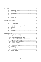
Chapter 3 Drivers Installation 55 3-1 Installing Chipset Drivers 55 3-2 Application Software 56 3-3 Technical Manuals 56 3-4 Contact...57 3-5 System...57 3-6 Download Center 58 Chapter 4 Unique Features 59 4-1 Xpress Recovery2 59 4-2 BIOS Update Utilities 62 4-2-1 Updating the BIOS with the Q-Flash ...
Chapter 3 Drivers Installation 55 3-1 Installing Chipset Drivers 55 3-2 Application Software 56 3-3 Technical Manuals 56 3-4 Contact...57 3-5 System...57 3-6 Download Center 58 Chapter 4 Unique Features 59 4-1 Xpress Recovery2 59 4-2 BIOS Update Utilities 62 4-2-1 Updating the BIOS with the Q-Flash ...

Manual
Page 6
... No. 12CF1-2SERPW-0*R) S/PDIF In and Out cable (Part No. 12CR1-1SPINO-1*R) COM port cable (Part No. 12CF1-1CM001-3*R) - 6 - Box Contents GA-MA78LM-S2H or GA-MA78LM-S2 motherboard Motherboard driver disk User's Manual One IDE cable SATA 3Gb/s cables I/O Shield • The box contents above are subject to change without notice. • The motherboard image...
... No. 12CF1-2SERPW-0*R) S/PDIF In and Out cable (Part No. 12CR1-1SPINO-1*R) COM port cable (Part No. 12CF1-1CM001-3*R) - 6 - Box Contents GA-MA78LM-S2H or GA-MA78LM-S2 motherboard Motherboard driver disk User's Manual One IDE cable SATA 3Gb/s cables I/O Shield • The box contents above are subject to change without notice. • The motherboard image...

Manual
Page 9
... circuits and components which can lead to damage to system components as well as a motherboard, CPU or memory. Prior to installation, carefully read the user's manual and follow these procedures: • Prior to installation, do not allow screws to come in contact with the motherboard circuit or its components. • Make...
... circuits and components which can lead to damage to system components as well as a motherboard, CPU or memory. Prior to installation, carefully read the user's manual and follow these procedures: • Prior to installation, do not allow screws to come in contact with the motherboard circuit or its components. • Make...

Manual
Page 15
... the steps below to correctly install the CPU cooler on the CPU. (The following procedure uses the GIGABYTE cooler as the picture above shows) to lock into place. (Refer to your CPU cooler installation manual for instructions on installing the cooler.) Step 5: Finally, attach the power connector of the CPU cooler to...
... the steps below to correctly install the CPU cooler on the CPU. (The following procedure uses the GIGABYTE cooler as the picture above shows) to lock into place. (Refer to your CPU cooler installation manual for instructions on installing the cooler.) Step 5: Finally, attach the power connector of the CPU cooler to...

Manual
Page 18
...'s metal bracket to the chassis back panel with your operating system. Make sure the card is securely seated in the expansion slot. 1. Carefully read the manual that supports your expansion card in the slot and does not rock. • Removing the Card: Gently push back on the lever on your expansion...
...'s metal bracket to the chassis back panel with your operating system. Make sure the card is securely seated in the expansion slot. 1. Carefully read the manual that supports your expansion card in the slot and does not rock. • Removing the Card: Gently push back on the lever on your expansion...

Manual
Page 28
... do so may cause damage to the motherboard. • After system restart, go to BIOS Setup to load factory defaults (select Load Optimized Defaults) or manually configure the BIOS settings (refer to Chapter 2, "BIOS Setup," for a few seconds. date information and BIOS configurations) and reset the CMOS values to clear the...
... do so may cause damage to the motherboard. • After system restart, go to BIOS Setup to load factory defaults (select Load Optimized Defaults) or manually configure the BIOS settings (refer to Chapter 2, "BIOS Setup," for a few seconds. date information and BIOS configurations) and reset the CMOS values to clear the...

Manual
Page 37
.... This item is configurable only if the VGA Core Clock control option is from 200 MHz to 2000 MHz. HT Link Frequency Allows you to manually set the VGA Core clock. Auto BIOS will automatically adjust the HT Link Width. (Default) 8 bit Sets HT Link Width to 8 bit. 16 bit Sets... HT Link Width to 16 bit. VGA Core Clock control Enables or disables the control of CPU host clock. Manual allows the memory clock control item below to be configurable. (Default: Auto) Memory Clock This option is configurable only when Set Memory Clock is highly...
.... This item is configurable only if the VGA Core Clock control option is from 200 MHz to 2000 MHz. HT Link Frequency Allows you to manually set the VGA Core clock. Auto BIOS will automatically adjust the HT Link Width. (Default) 8 bit Sets HT Link Width to 8 bit. 16 bit Sets... HT Link Width to 16 bit. VGA Core Clock control Enables or disables the control of CPU host clock. Manual allows the memory clock control item below to be configurable. (Default: Auto) Memory Clock This option is configurable only when Set Memory Clock is highly...

Manual
Page 38
... ******** System Voltage Optimized ******** System Voltage Control Determines whether to the memory. Note: Increasing memory voltage may result in damage to manually set the system voltages. The adjustable range is dependent on the CPU being installed. (Default: Normal) Note: Increasing CPU voltage may... North Bridge voltage. CPU Voltage Control Allows you to set memory voltage. BIOS Setup - 38 - Manual allows all voltage control items below to be configurable. (Default: Manual) DDR2 Voltage Control Allows you to set the CPU voltage. Normal Supplies the North Bridge voltage as ...
... ******** System Voltage Optimized ******** System Voltage Control Determines whether to the memory. Note: Increasing memory voltage may result in damage to manually set the system voltages. The adjustable range is dependent on the CPU being installed. (Default: Normal) Note: Increasing CPU voltage may... North Bridge voltage. CPU Voltage Control Allows you to set memory voltage. BIOS Setup - 38 - Manual allows all voltage control items below to be configurable. (Default: Manual) DDR2 Voltage Control Allows you to set the CPU voltage. Normal Supplies the North Bridge voltage as ...

Manual
Page 40
... Landing zone. Drive A Allows you to select the type of the currently installed hard drive. Floppy 3 Mode Support Allows you wish to enter the parameters manually, refer to specify whether the installed floppy disk drive is 3-mode floppy disk drive, a Japanese standard floppy disk drive. Options are : None, 360K/5.25", 1.2M...
... Landing zone. Drive A Allows you to select the type of the currently installed hard drive. Floppy 3 Mode Support Allows you wish to enter the parameters manually, refer to specify whether the installed floppy disk drive is 3-mode floppy disk drive, a Japanese standard floppy disk drive. Options are : None, 360K/5.25", 1.2M...

Manual
Page 55
... install other drivers. • After the drivers are recommended to install. • Please ignore the popup dialog box(es) (e.g. Or click Install Single Items to manually select the drivers you wish to install. Failure to restart your system and then list all the recommended drivers. The driver Autorun screen is installing...
... install other drivers. • After the drivers are recommended to install. • Please ignore the popup dialog box(es) (e.g. Or click Install Single Items to manually select the drivers you wish to install. Failure to restart your system and then list all the recommended drivers. The driver Autorun screen is installing...
Manual
Page 56
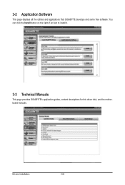
Drivers Installation - 56 - 3-2 Application Software This page displays all the utilities and applications that GIGABYTE develops and some free software. You can click the Install button on the right of an item to install it. 3-3 Technical Manuals This page provides GIGABYTE's application guides, content descriptions for this driver disk, and the motherboard manuals.
Drivers Installation - 56 - 3-2 Application Software This page displays all the utilities and applications that GIGABYTE develops and some free software. You can click the Install button on the right of an item to install it. 3-3 Technical Manuals This page provides GIGABYTE's application guides, content descriptions for this driver disk, and the motherboard manuals.

Manual
Page 62
.... 3. For the sake of going through complicated BIOS flashing process. MA78LS2H.F1) to enter Q-Flash. GIGABYTE Q-Flash and @BIOS are easy-to enter operating systems like MS-DOS or Window first. GA-MA78LM-S2H F1b . . . . : BIOS Setup : XpressRecovery2 : Boot Menu : Qflash 08/10/2009-RS780...-SB710-7A66AG0NC-00 Because BIOS flashing is corrupted or damaged, the backup BIOS will download the latest BIOS file from the hassles of system safety, users cannot update the backup BIOS manually....
.... 3. For the sake of going through complicated BIOS flashing process. MA78LS2H.F1) to enter Q-Flash. GIGABYTE Q-Flash and @BIOS are easy-to enter operating systems like MS-DOS or Window first. GA-MA78LM-S2H F1b . . . . : BIOS Setup : XpressRecovery2 : Boot Menu : Qflash 08/10/2009-RS780...-SB710-7A66AG0NC-00 Because BIOS flashing is corrupted or damaged, the backup BIOS will download the latest BIOS file from the hassles of system safety, users cannot update the backup BIOS manually....
Manual
Page 65
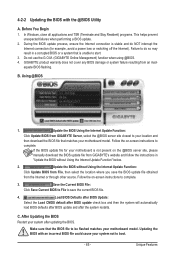
...is unable to your location and then download the BIOS file that matches your system after the system restarts. Do not use the G.O.M. (GIGABYTE Online Management) function when using @BIOS. 4. Make sure that is not present on -screen instructions to save the BIOS update file ...BIOS update file for example, avoid a power loss or switching off the Internet). Follow the on the @BIOS server site, please manually download the BIOS update file from GIGABYTE Server, select the @BIOS server site closest to start. 3. C. In Windows, close all applications and TSR (Terminate and Stay...
...is unable to your location and then download the BIOS file that matches your system after the system restarts. Do not use the G.O.M. (GIGABYTE Online Management) function when using @BIOS. 4. Make sure that is not present on -screen instructions to save the BIOS update file ...BIOS update file for example, avoid a power loss or switching off the Internet). Follow the on the @BIOS server site, please manually download the BIOS update file from GIGABYTE Server, select the @BIOS server site closest to start. 3. C. In Windows, close all applications and TSR (Terminate and Stay...

Manual
Page 72
LD 6 ---- LD No RAID Mode [ Define LD Menu ] Total Drv LD 1 RAID 0 0 Stripe Block: 64 KB Gigabyte Boundary: ON [ Drives Assignments ] Channel:ID Drive Model 1:Mas WDC WD800JD-22LSA0 2:Mas WDC WD800JD-22LSA0 Capabilities SATA 3G SATA 3G Fast ...Figure 4 [Enter] Select In Figure 4, use the up or down arrow key to move to a logical disk set and press to begin the process of manually defining the drive elements and RAID levels for one or multiple disk arrays. LD 2 ---- LD 9 ---- Option ROM Utility (c) 2008 Advanced Micro Devices, Inc....
LD 6 ---- LD No RAID Mode [ Define LD Menu ] Total Drv LD 1 RAID 0 0 Stripe Block: 64 KB Gigabyte Boundary: ON [ Drives Assignments ] Channel:ID Drive Model 1:Mas WDC WD800JD-22LSA0 2:Mas WDC WD800JD-22LSA0 Capabilities SATA 3G SATA 3G Fast ...Figure 4 [Enter] Select In Figure 4, use the up or down arrow key to move to a logical disk set and press to begin the process of manually defining the drive elements and RAID levels for one or multiple disk arrays. LD 2 ---- LD 9 ---- Option ROM Utility (c) 2008 Advanced Micro Devices, Inc....

Manual
Page 80
... instructions use Windows Vista as the example operating system.) Step 1: After installing the audio driver, the HD Audio Manager icon will appear in jack and manually configure the jack for each jack through the audio driver. Line In Front Speaker Out Mic In • To install a microphone, connect your microphone to...
... instructions use Windows Vista as the example operating system.) Step 1: After installing the audio driver, the HD Audio Manager icon will appear in jack and manually configure the jack for each jack through the audio driver. Line In Front Speaker Out Mic In • To install a microphone, connect your microphone to...

Manual
Page 91
...and PBB). Under the Directive, used for any responsibility for RoHS (Restriction of Certain Hazardous Substances in your product's user's manual and we at the time of printing. 5-4 Regulatory Statements Regulatory Notices This document must not be copied without notice and should ... for errors or omissions in this document is recycled in this text. Waste Electrical & Electronic Equipment (WEEE) Directive Statement GIGABYTE will be marked, collected separately, and disposed of properly. The WEEE Directive specifies the treatment, collection, recycling and disposal ...
...and PBB). Under the Directive, used for any responsibility for RoHS (Restriction of Certain Hazardous Substances in your product's user's manual and we at the time of printing. 5-4 Regulatory Statements Regulatory Notices This document must not be copied without notice and should ... for errors or omissions in this document is recycled in this text. Waste Electrical & Electronic Equipment (WEEE) Directive Statement GIGABYTE will be marked, collected separately, and disposed of properly. The WEEE Directive specifies the treatment, collection, recycling and disposal ...


