Manual
Page 4
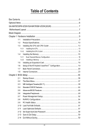
... Contents Box Contents...6 Optional Items...6 GA-MA785GPM-UD2H/GA-MA78GM-UD2H(US2H 7 Motherboard Layout...7 Block Diagram...8 Chapter 1 Hardware Installation 9 1-1 Installation Precautions 9 1-2 Product Specifications 10 1-3 Installing the CPU and CPU Cooler 13 1-3-1 Installing the CPU 13 1-3-2 Installing the CPU Cooler 15 1-4 Installing the Memory 16 1-4-1 Dual Channel Memory Configuration 16 1-4-2 Installing a Memory 17 1-5 Installing an Expansion Card...
... Contents Box Contents...6 Optional Items...6 GA-MA785GPM-UD2H/GA-MA78GM-UD2H(US2H 7 Motherboard Layout...7 Block Diagram...8 Chapter 1 Hardware Installation 9 1-1 Installation Precautions 9 1-2 Product Specifications 10 1-3 Installing the CPU and CPU Cooler 13 1-3-1 Installing the CPU 13 1-3-2 Installing the CPU Cooler 15 1-4 Installing the Memory 16 1-4-1 Dual Channel Memory Configuration 16 1-4-2 Installing a Memory 17 1-5 Installing an Expansion Card...
Manual
Page 8
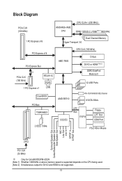
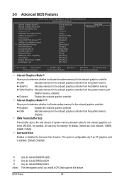
Block Diagram PCIe CLK (100 MHz) AM3/AM2+/AM2 CPU CPU CLK+/- (200 MHz) DDR2 1200(O.C.)/1066(Note 1)/800 MHz 1 PCI Express x16 Dual Channel Memory Hyper Transport 3.0 PCI Express x16 PCI Express Bus x1 PCIe CLK (100 MHz) 1 PCI Express x1 RTL8111C RJ45 LAN Dual BIOS PCI Bus TSB43AB23 2 .../Subwoofer Speaker Out Side Speaker Out MIC Line Out Line In S/PDIF In S/ PDIF Out 2 PCI PCI CLK (33 MHz) j Only for GA-MA785GPM-UD2H. (Note 1) Whether 1066 MHz or above memory speed is supported depends on the CPU being used. (Note 2) Simultaneous output for DVI-D and HDMI is not supported. - 8 -
Block Diagram PCIe CLK (100 MHz) AM3/AM2+/AM2 CPU CPU CLK+/- (200 MHz) DDR2 1200(O.C.)/1066(Note 1)/800 MHz 1 PCI Express x16 Dual Channel Memory Hyper Transport 3.0 PCI Express x16 PCI Express Bus x1 PCIe CLK (100 MHz) 1 PCI Express x1 RTL8111C RJ45 LAN Dual BIOS PCI Bus TSB43AB23 2 .../Subwoofer Speaker Out Side Speaker Out MIC Line Out Line In S/PDIF In S/ PDIF Out 2 PCI PCI CLK (33 MHz) j Only for GA-MA785GPM-UD2H. (Note 1) Whether 1066 MHz or above memory speed is supported depends on the CPU being used. (Note 2) Simultaneous output for DVI-D and HDMI is not supported. - 8 -
Manual
Page 9
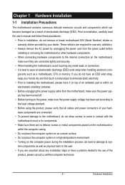
... as physical harm to the user. • If you do not have an ESD wrist strap, keep your dealer. ponents such as a motherboard, CPU or memory. Hardware Installation These stickers are required for warranty validation. • Always remove the AC power by your hands dry and first touch a metal object to...
... as physical harm to the user. • If you do not have an ESD wrist strap, keep your dealer. ponents such as a motherboard, CPU or memory. Hardware Installation These stickers are required for warranty validation. • Always remove the AC power by your hands dry and first touch a metal object to...
Manual
Page 10
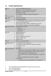
...GA-MA785GM-UD2H adopts All-Solid Capacitor design. 1-2 Product Specifications CPU Support for AM3/AM2+/AM2 processors: AMD Phenom™ II processor/ AMD Phenom™ processor/ AMD Athlon™ II processor/ AMD Athlon™ processor/ AMD Sempron™ processor (Go to GIGABYTE...Bridge: AMD SB710 4 x 1.8V DDR2 DIMM sockets supporting up to 16 GB of system memory (Note 1) Dual channel memory architecture Support for DDR2 1200(O.C.)/1066 (Note 2)/800 MHz memory modules (Go to GIGABYTE's website for the latest memory support list.) Integrated in the North Bridge: - 1 x D-Sub port - 1 x...
...GA-MA785GM-UD2H adopts All-Solid Capacitor design. 1-2 Product Specifications CPU Support for AM3/AM2+/AM2 processors: AMD Phenom™ II processor/ AMD Phenom™ processor/ AMD Athlon™ II processor/ AMD Athlon™ processor/ AMD Sempron™ processor (Go to GIGABYTE...Bridge: AMD SB710 4 x 1.8V DDR2 DIMM sockets supporting up to 16 GB of system memory (Note 1) Dual channel memory architecture Support for DDR2 1200(O.C.)/1066 (Note 2)/800 MHz memory modules (Go to GIGABYTE's website for the latest memory support list.) Integrated in the North Bridge: - 1 x D-Sub port - 1 x...
Manual
Page 12
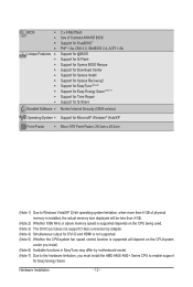
... (Note 1) Due to Windows Vista/XP 32-bit operating system limitation, when more than 4 GB of physical memory is installed, the actual memory size displayed will be less than 4 GB. (Note 2) Whether 1066 MHz or above memory speed is supported depends on the CPU being used. (Note 3) The DVI-D port does not support...
... (Note 1) Due to Windows Vista/XP 32-bit operating system limitation, when more than 4 GB of physical memory is installed, the actual memory size displayed will be less than 4 GB. (Note 2) Whether 1066 MHz or above memory speed is supported depends on the CPU being used. (Note 3) The DVI-D port does not support...

Manual
Page 13
1-3 Installing the CPU and CPU Cooler Read the following guidelines before installing the CPU to your hardware specifications including the CPU, graphics card, memory, hard drive, etc. 1-3-1 Installing the CPU A. If you may occur. • Set the CPU host frequency in accordance with the CPU specifications. ...cord from the power outlet before you begin to install the CPU: • Make sure that the motherboard supports the CPU. (Go to GIGABYTE's website for the latest CPU support list.) • Always turn on the computer if the CPU cooler is not recommended that the system ...
1-3 Installing the CPU and CPU Cooler Read the following guidelines before installing the CPU to your hardware specifications including the CPU, graphics card, memory, hard drive, etc. 1-3-1 Installing the CPU A. If you may occur. • Set the CPU host frequency in accordance with the CPU specifications. ...cord from the power outlet before you begin to install the CPU: • Make sure that the motherboard supports the CPU. (Go to GIGABYTE's website for the latest CPU support list.) • Always turn on the computer if the CPU cooler is not recommended that the system ...
Manual
Page 16
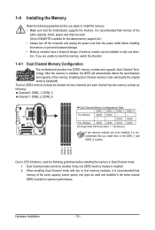
... be enabled if only one direction. 1-4 Installing the Memory Read the following guidelines before you begin to install the memory: • Make sure that memory of the same capacity, brand, speed, and chips be used . (Go to GIGABYTE's website for optimum performance. The four DDR2 memory sockets are to CPU limitations, read the following guidelines...
... be enabled if only one direction. 1-4 Installing the Memory Read the following guidelines before you begin to install the memory: • Make sure that memory of the same capacity, brand, speed, and chips be used . (Go to GIGABYTE's website for optimum performance. The four DDR2 memory sockets are to CPU limitations, read the following guidelines...

Manual
Page 17
... insert it can only fit in one direction. Step 1: Note the orientation of the memory socket. As indicated in the memory sockets. 1-4-2 Installing a Memory Before installing a memory module, make sure to turn off the computer and unplug the power cord from the power outlet to prevent damage to install DDR2 ...DIMMs on this motherboard. DDR2 DIMMs are not compatible to DDR DIMMs. Be sure to the memory module. Follow the steps below to correctly install your memory modules in the picture on the left, place your fingers on the top edge of the socket will snap into...
... insert it can only fit in one direction. Step 1: Note the orientation of the memory socket. As indicated in the memory sockets. 1-4-2 Installing a Memory Before installing a memory module, make sure to turn off the computer and unplug the power cord from the power outlet to prevent damage to install DDR2 ...DIMMs on this motherboard. DDR2 DIMMs are not compatible to DDR DIMMs. Be sure to the memory module. Follow the steps below to correctly install your memory modules in the picture on the left, place your fingers on the top edge of the socket will snap into...
Manual
Page 21
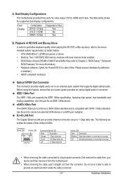
... a back panel connector, first remove the cable from the connector. The table below . • CPU: AMD Athlon™ LE1640 processor or above • Memory: Two 1 GB DDR2 800 memory modules with SATA 1.5Gb/s standard. IEEE 1394a Port The IEEE 1394 port supports the IEEE 1394a specification, featuring high speed, high bandwidth and...
... a back panel connector, first remove the cable from the connector. The table below . • CPU: AMD Athlon™ LE1640 processor or above • Memory: Two 1 GB DDR2 800 memory modules with SATA 1.5Gb/s standard. IEEE 1394a Port The IEEE 1394 port supports the IEEE 1394a specification, featuring high speed, high bandwidth and...

Manual
Page 38
... menu to configure the system's PCI & PnP resources. PC Health Status Use this function to load the BIOS settings from BIOS If your CPU, memory, etc. Standard CMOS Features Use this menu to configure the system time and date, hard drive types, floppy disk drive types, and the type...
... menu to configure the system's PCI & PnP resources. PC Health Status Use this function to load the BIOS settings from BIOS If your CPU, memory, etc. Standard CMOS Features Use this menu to configure the system time and date, hard drive types, floppy disk drive types, and the type...
Manual
Page 39
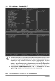
...CPU Host Clock Control x CPU Frequency(MHz) PCIE Clock(MHz) VGA Core Clock control x VGA Core Clock(MHz) Set Memory Clock x Memory Clock DCTs Mode (Note) } DRAM Configuration ******** System Voltage Optimized ******** System Voltage Control DDR2 Voltage Control NorthBridge Volt Control ...instability or other unexpected results. (Inadequately altering the settings may result in system's failure to CPU, chipset, or memory and reduce the useful life of these components. This page is dependent on your overall system configurations. Incorrectly doing...
...CPU Host Clock Control x CPU Frequency(MHz) PCIE Clock(MHz) VGA Core Clock control x VGA Core Clock(MHz) Set Memory Clock x Memory Clock DCTs Mode (Note) } DRAM Configuration ******** System Voltage Optimized ******** System Voltage Control DDR2 Voltage Control NorthBridge Volt Control ...instability or other unexpected results. (Inadequately altering the settings may result in system's failure to CPU, chipset, or memory and reduce the useful life of these components. This page is dependent on your overall system configurations. Incorrectly doing...
Manual
Page 41
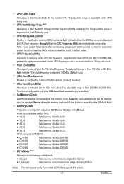
.... The adjustable range is dependent on the CPU being used . When you to manually set to manually set memory control mode. Ganged Sets memory control mode to X2.00. Unganged Sets memory control mode to be configurable. Manual allows the CPU Frequency (MHz) item below to standard 100 MHz. (Default... the control of VGA Core clock. (Default: Disabled) VGA Core Clock(MHz) Allows you use an AM3/AM2+ CPU: X2.00 Sets Memory Clock to single dual-channel. Note: If your system fails to boot after overclocking, please wait for 20 seconds to allow for the installed ...
.... The adjustable range is dependent on the CPU being used . When you to manually set to manually set memory control mode. Ganged Sets memory control mode to X2.00. Unganged Sets memory control mode to be configurable. Manual allows the CPU Frequency (MHz) item below to standard 100 MHz. (Default... the control of VGA Core clock. (Default: Disabled) VGA Core Clock(MHz) Allows you use an AM3/AM2+ CPU: X2.00 Sets Memory Clock to single dual-channel. Note: If your system fails to boot after overclocking, please wait for 20 seconds to allow for the installed ...
Manual
Page 43
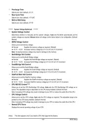
... Increases South Bridge voltage by 0.1V to 0.3V at 0.1V increment. Auto sets the CPU Northbridge VID voltage as required. Normal Supplies the SidePort memory voltage as required. (Default) +0.1V ~ +0.3V Increases North Bridge voltage by 0.1V to 0.3V at 0.1V increment. Precharge Time Options are ... Allows you to set the CPU Northbridge VID voltage. Normal Supplies the North Bridge voltage as required. (Default) +0.1V ~ +0.3V Increases SidePort memory voltage by 0.1V to RAS Delay Options are : Auto (default), 2T, 3T. RAS to 0.3V at 0.1V increment. CPU Voltage Control...
... Increases South Bridge voltage by 0.1V to 0.3V at 0.1V increment. Auto sets the CPU Northbridge VID voltage as required. Normal Supplies the SidePort memory voltage as required. (Default) +0.1V ~ +0.3V Increases North Bridge voltage by 0.1V to 0.3V at 0.1V increment. Precharge Time Options are ... Allows you to set the CPU Northbridge VID voltage. Normal Supplies the North Bridge voltage as required. (Default) +0.1V ~ +0.3V Increases SidePort memory voltage by 0.1V to RAS Delay Options are : Auto (default), 2T, 3T. RAS to 0.3V at 0.1V increment. CPU Voltage Control...
Manual
Page 44
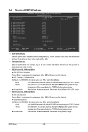
... 3 Master } IDE Channel 3 Slave [None] [None] [None] [None] [None] [None] [None] [None] Drive A Floppy 3 Mode Support [1.44M, 3.5"] [Disabled] Halt On [All, But Keyboard] Base Memory Extended Memory 640K 1790M Move Enter: Select F5: Previous Values +/-/PU/PD: Value F10: Save F6: Fail-Safe Defaults ESC: Exit F1: General Help F7: Optimized Defaults...
... 3 Master } IDE Channel 3 Slave [None] [None] [None] [None] [None] [None] [None] [None] Drive A Floppy 3 Mode Support [1.44M, 3.5"] [Disabled] Halt On [All, But Keyboard] Base Memory Extended Memory 640K 1790M Move Enter: Select F5: Previous Values +/-/PU/PD: Value F10: Save F6: Fail-Safe Defaults ESC: Exit F1: General Help F7: Optimized Defaults...

Manual
Page 45
... boot will not stop for a floppy disk drive error but stop for an error during the POST. BIOS Setup Cylinder Number of extended memory. - 45 - Options are determined by the BIOS POST. No Errors The system boot will stop for the MS-DOS operating system. ...all other errors. (Default) All, But Diskette The system boot will stop for all other errors. Typically, 640 KB will stop . Extended Memory The amount of cylinders. Head Number of floppy disk drive installed in your hard drive specifications. Drive A Allows you to None. Floppy 3 ...
... boot will not stop for a floppy disk drive error but stop for an error during the POST. BIOS Setup Cylinder Number of extended memory. - 45 - Options are determined by the BIOS POST. No Errors The system boot will stop for the MS-DOS operating system. ...all other errors. (Default) All, But Diskette The system boot will stop for all other errors. Typically, 640 KB will stop . Extended Memory The amount of cylinders. Head Number of floppy disk drive installed in your hard drive specifications. Drive A Allows you to None. Floppy 3 ...
Manual
Page 46
... the onboard graphics controller. Capability Away Mode Backup BIOS Image to allocate system memory for the onboard graphics controller. SidePort Allocates memory for display. UMA+SidePort Allocates memory for GA-MA785GM-US2H. Only for the onboard graphics controller from the system memory. Disabled Disables the onboard graphics controller. This option is configurable only if an ATI graphics...
... the onboard graphics controller. Capability Away Mode Backup BIOS Image to allocate system memory for the onboard graphics controller. SidePort Allocates memory for display. UMA+SidePort Allocates memory for GA-MA785GM-US2H. Only for the onboard graphics controller from the system memory. Disabled Disables the onboard graphics controller. This option is configurable only if an ATI graphics...

Manual
Page 53
... is set a password with 1~5 characters to turn on the +5VSB lead. Resume Time (hh: mm: ss): Set the time at least 1A on the system. Memory The system returns to its last known awake state upon the return of power from a PCI or PCIe device. BIOS Setup PME Event Wake Up...
... is set a password with 1~5 characters to turn on the +5VSB lead. Resume Time (hh: mm: ss): Set the time at least 1A on the system. Memory The system returns to its last known awake state upon the return of power from a PCI or PCIe device. BIOS Setup PME Event Wake Up...

Manual
Page 65
... drive (Note) for the operating system. When hard drives are different utilities. Installation and Configuration: Turn on your system data and perform restoration of system memory • VESA compatible graphics card • Windows XP with Xpress Recovery cannot be restored using Xpress Recovery2. • USB hard drives are not supported. •...
... drive (Note) for the operating system. When hard drives are different utilities. Installation and Configuration: Turn on your system data and perform restoration of system memory • VESA compatible graphics card • Windows XP with Xpress Recovery cannot be restored using Xpress Recovery2. • USB hard drives are not supported. •...

Manual
Page 72
... or system instability or other unexpected results may occur. You can choose the alert sound from a profile. You can select memory module on the installed CPU and motherboard. Unique Features - 72 - Grayed-out area(s) indicates that you to load previous settings... you to specify a C.I.A.2 level and a Smart Fan mode. Incorrectly doing overclock/overvoltage may differ by motherboard model. 4-3 EasyTune 6 GIGABYTE's EasyTune 6 is a simple and easy-to-use interface that allows users to fine-tune their system-related information without the need to...
... or system instability or other unexpected results may occur. You can choose the alert sound from a profile. You can select memory module on the installed CPU and motherboard. Unique Features - 72 - Grayed-out area(s) indicates that you to load previous settings... you to specify a C.I.A.2 level and a Smart Fan mode. Incorrectly doing overclock/overvoltage may differ by motherboard model. 4-3 EasyTune 6 GIGABYTE's EasyTune 6 is a simple and easy-to-use interface that allows users to fine-tune their system-related information without the need to...

Manual
Page 79
... 1..4 to enter FastBuild (tm) Utility" (Figure 2). RAID Option ROM Version 3.0.1540.33 (c) 2008 Advanced Micro Devices, Inc. All rights reserved. Appendix C. Step 1: After the POST memory test begins and before the operating system boot begins, look for a non-RAID configuration. To create an array, press to enter the Controller Configuration window...
... 1..4 to enter FastBuild (tm) Utility" (Figure 2). RAID Option ROM Version 3.0.1540.33 (c) 2008 Advanced Micro Devices, Inc. All rights reserved. Appendix C. Step 1: After the POST memory test begins and before the operating system boot begins, look for a non-RAID configuration. To create an array, press to enter the Controller Configuration window...


