Manual
Page 4
Table of Contents Box Contents ...6 OptionalItems ...6 GA-MA770T-UD3/US3 Motherboard Layout 7 Block Diagram ...8 Chapter 1 Hardware Installation 9 1-1 Installation Precautions 9 1-2 Product Specifications 10 1-3 Installing the CPU and CPU Cooler 13 1-3-1 Installing the CPU 13 1-3-2 Installing the CPU Cooler 15 1-4 Installing the Memory 16 1-4-1 Dual Channel Memory Configuration 16 1-4-2 Installing a Memory 17 1-5 Installing an Expansion Card 18 1-6 Back Panel...
Table of Contents Box Contents ...6 OptionalItems ...6 GA-MA770T-UD3/US3 Motherboard Layout 7 Block Diagram ...8 Chapter 1 Hardware Installation 9 1-1 Installation Precautions 9 1-2 Product Specifications 10 1-3 Installing the CPU and CPU Cooler 13 1-3-1 Installing the CPU 13 1-3-2 Installing the CPU Cooler 15 1-4 Installing the Memory 16 1-4-1 Dual Channel Memory Configuration 16 1-4-2 Installing a Memory 17 1-5 Installing an Expansion Card 18 1-6 Back Panel...
Manual
Page 8
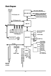
Block Diagram PCIe CLK (100 MHz) 1 PCI Express x16 PCI Express x16 CPU CLK+/-(200 MHz) AM3+/AM3 CPU DDR3 1666(O.C.)/1333/1066 MHz Dual Channel Memory Hyper Transport 3.0 PCI Express Bus x1 x1 x1 x1 AMD 770 PCIe CLK x1 (100 MHz) 4 PCI Express x1 RTL8111D/E RJ45 LAN PCI Bus TSB43AB23 3 IEEE 1394a AMD SB710 CODEC ATA-133/100/66/33 IDE Channel 6 SATA 3Gb/s 12 USB Ports IT8720 Dual BIOS Floppy LPT Port COM Port PS/2 KB/Mouse Surround Speaker Out Center/Subwoofer Speaker Out Side Speaker Out MIC Line Out Line In S/PDIF In S/PDIF Out 2 PCI PCI CLK (33 MHz) - 8 -
Block Diagram PCIe CLK (100 MHz) 1 PCI Express x16 PCI Express x16 CPU CLK+/-(200 MHz) AM3+/AM3 CPU DDR3 1666(O.C.)/1333/1066 MHz Dual Channel Memory Hyper Transport 3.0 PCI Express Bus x1 x1 x1 x1 AMD 770 PCIe CLK x1 (100 MHz) 4 PCI Express x1 RTL8111D/E RJ45 LAN PCI Bus TSB43AB23 3 IEEE 1394a AMD SB710 CODEC ATA-133/100/66/33 IDE Channel 6 SATA 3Gb/s 12 USB Ports IT8720 Dual BIOS Floppy LPT Port COM Port PS/2 KB/Mouse Surround Speaker Out Center/Subwoofer Speaker Out Side Speaker Out MIC Line Out Line In S/PDIF In S/PDIF Out 2 PCI PCI CLK (33 MHz) - 8 -

Manual
Page 9
... components. • When connecting hardware components to the internal connectors on the computer power during the installation process can become damaged as a motherboard, CPU or memory. These stickers are connected tightly and securely. • When handling the motherboard, avoid touching any installation steps or have a problem related to wear an electrostatic...
... components. • When connecting hardware components to the internal connectors on the computer power during the installation process can become damaged as a motherboard, CPU or memory. These stickers are connected tightly and securely. • When handling the motherboard, avoid touching any installation steps or have a problem related to wear an electrostatic...
Manual
Page 10
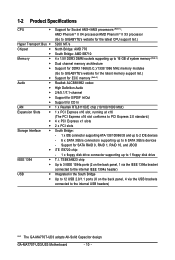
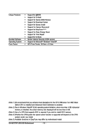
...the back panel, 4 via the USB brackets connected to the internal USB headers) "*" The GA-MA770T-UD3 adopts All-Solid Capacitor design. 1-2 Product Specifications CPU Hyper Transport Bus Chipset Memory Audio ... supporting up to 16 GB of system memory (Note 2) Dual channel memory architecture Support for DDR3 1666(O.C.)/1333/1066 MHz memory modules (Go to GIGABYTE's website for the latest memory support list.) Support for ECC memory (Note 3) Realtek ALC888/892 codec High...
...the back panel, 4 via the USB brackets connected to the internal USB headers) "*" The GA-MA770T-UD3 adopts All-Solid Capacitor design. 1-2 Product Specifications CPU Hyper Transport Bus Chipset Memory Audio ... supporting up to 16 GB of system memory (Note 2) Dual channel memory architecture Support for DDR3 1666(O.C.)/1333/1066 MHz memory modules (Go to GIGABYTE's website for the latest memory support list.) Support for ECC memory (Note 3) Realtek ALC888/892 codec High...
Manual
Page 12
...Clock Calibration is enabled. (Note 2) Due to Windows Vista/XP 32-bit operating system limitation, when more than 4 GB of physical memory is installed, the actual memory size displayed will be less than 4 GB. (Note 3) Use of a CPU that supports ECC is required if you wish to ...install ECC memory. (Note 4) Whether the CPU/system fan speed control function is supported will depend on the CPU/ system cooler you install. (Note 5) Available functions in EasyTune may differ by motherboard model. GA-MA770T-UD3/US3 Motherboard - 12 -
...Clock Calibration is enabled. (Note 2) Due to Windows Vista/XP 32-bit operating system limitation, when more than 4 GB of physical memory is installed, the actual memory size displayed will be less than 4 GB. (Note 3) Use of a CPU that supports ECC is required if you wish to ...install ECC memory. (Note 4) Whether the CPU/system fan speed control function is supported will depend on the CPU/ system cooler you install. (Note 5) Available functions in EasyTune may differ by motherboard model. GA-MA770T-UD3/US3 Motherboard - 12 -

Manual
Page 13
... the CPU. 1-3 Installing the CPU and CPU Cooler Read the following guidelines before installing the CPU to your hardware specifications including the CPU, graphics card, memory, hard drive, etc. 1-3-1 Installing the CPU A. mended that the motherboard supports the CPU. (Go to...
... the CPU. 1-3 Installing the CPU and CPU Cooler Read the following guidelines before installing the CPU to your hardware specifications including the CPU, graphics card, memory, hard drive, etc. 1-3-1 Installing the CPU A. mended that the motherboard supports the CPU. (Go to...
Manual
Page 16
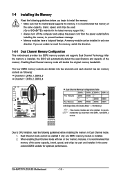
...recommended that the motherboard supports the memory. DS/SS DS/SS Four Modules DS/SS DS/SS DS/SS DS/SS (SS=Single-Sided, DS=Double-Sided, "- -"=No Memory) If two memory modules are unable to GIGABYTE's website for optimum performance. GA-MA770T-UD3/US3 Motherboard - 16 - When... enabling Dual Channel mode with two or four memory modules, it is recommended that memory of the same capacity, brand, speed, and ...
...recommended that the motherboard supports the memory. DS/SS DS/SS Four Modules DS/SS DS/SS DS/SS DS/SS (SS=Single-Sided, DS=Double-Sided, "- -"=No Memory) If two memory modules are unable to GIGABYTE's website for optimum performance. GA-MA770T-UD3/US3 Motherboard - 16 - When... enabling Dual Channel mode with two or four memory modules, it is recommended that memory of the same capacity, brand, speed, and ...

Manual
Page 17
... Note the orientation of the socket will snap into the memory socket. Hardware Installation As indicated in the picture on the left, place your memory modules in the memory sockets. Follow the steps below to the memory module. 1-4-2 Installing a Memory Before installing a memory module , make sure to turn off the computer and ...unplug the power cord from the power outlet to prevent damage to correctly install your fingers on the top edge of the memory socket. DDR3 and DDR2 DIMMs are not compatible to each other or DDR DIMMs. Be sure to install DDR3 DIMMs on the socket...
... Note the orientation of the socket will snap into the memory socket. Hardware Installation As indicated in the picture on the left, place your memory modules in the memory sockets. Follow the steps below to the memory module. 1-4-2 Installing a Memory Before installing a memory module , make sure to turn off the computer and ...unplug the power cord from the power outlet to prevent damage to correctly install your fingers on the top edge of the memory socket. DDR3 and DDR2 DIMMs are not compatible to each other or DDR DIMMs. Be sure to install DDR3 DIMMs on the socket...
Manual
Page 36
... of your system becomes unstable and you have loaded the BIOS default settings, you can use this task.) GA-MA770T-UD3/US3 Motherboard - 36 - Pressing to load the BIOS settings from BIOS If your CPU, memory, etc. Standard CMOS Features Use this menu to configure the system time and date, hard drive types...
... of your system becomes unstable and you have loaded the BIOS default settings, you can use this task.) GA-MA770T-UD3/US3 Motherboard - 36 - Pressing to load the BIOS settings from BIOS If your CPU, memory, etc. Standard CMOS Features Use this menu to configure the system time and date, hard drive types...

Manual
Page 37
... result in damage to optimize the system voltage settings. BIOS Setup CPU Host Clock Control x CPU Frequency (MHz) PCIE Clock (MHz) HT Link Frequency Set Memory Clock x Memory Clock DRAM Configuration ******** System Voltage Optimized System Voltage Control x CPU NB VID Control x CPU Voltage Control Normal CPU Vcore x DRAM Voltage control x DDR... • Whether the system will work stably with the overclock/overvoltage settings you set the System Voltage Control item to Auto to CPU, chipset, or memory and reduce the useful life of these components.
... result in damage to optimize the system voltage settings. BIOS Setup CPU Host Clock Control x CPU Frequency (MHz) PCIE Clock (MHz) HT Link Frequency Set Memory Clock x Memory Clock DRAM Configuration ******** System Voltage Optimized System Voltage Control x CPU NB VID Control x CPU Voltage Control Normal CPU Vcore x DRAM Voltage control x DDR... • Whether the system will work stably with the overclock/overvoltage settings you set the System Voltage Control item to Auto to CPU, chipset, or memory and reduce the useful life of these components.
Manual
Page 38
...(MHz) Allows you to x5.33. Manual allows the memory clock control item below to x4.00. x5.33 Sets Memory Clock to alter the clock ratio for automated system reboot, or clear the CMOS values to reset the board to All Cores. GA-MA770T-UD3/US3 Motherboard - 38 - Options are : -12%~+12%.... to x8.00. The adjustable range is highly recommended that you to 200 MHz. Important It is from 100 MHz to manually set the memory clock. Auto BIOS will automatically adjust the HT Link Frequency. (Default) 200 MHz~2 GHz Sets HT Link Frequency to manually set the frequency...
...(MHz) Allows you to x5.33. Manual allows the memory clock control item below to x4.00. x5.33 Sets Memory Clock to alter the clock ratio for automated system reboot, or clear the CMOS values to reset the board to All Cores. GA-MA770T-UD3/US3 Motherboard - 38 - Options are : -12%~+12%.... to x8.00. The adjustable range is highly recommended that you to 200 MHz. Important It is from 100 MHz to manually set the memory clock. Auto BIOS will automatically adjust the HT Link Frequency. (Default) 200 MHz~2 GHz Sets HT Link Frequency to manually set the frequency...

Manual
Page 39
DRAM Configuration CMOS Setup Utility-Copyright (C) 1984-2009 Award Software DRAM Configuration CPU Host Clock Control x CPU Frequency (MHz) Set Memory Clock x Memory Clock DCTs Mode [Auto] 200 [Auto] x5.33 1066Mhz [Unganged] Item Help Menu Level DDR3 Timing Items x CAS# latency x RAS...: General Help F7: Optimized Defaults CPU Host Clock Control, CPU Frequency (MHz), Set Memory Clock, Memory Clock The settings under the four items above are : Auto (default), Manual. - 39 - Sets memory control mode to two single-channel.(default) DDR3 Timing Items Manual allows all DDR3 Timing ...
DRAM Configuration CMOS Setup Utility-Copyright (C) 1984-2009 Award Software DRAM Configuration CPU Host Clock Control x CPU Frequency (MHz) Set Memory Clock x Memory Clock DCTs Mode [Auto] 200 [Auto] x5.33 1066Mhz [Unganged] Item Help Menu Level DDR3 Timing Items x CAS# latency x RAS...: General Help F7: Optimized Defaults CPU Host Clock Control, CPU Frequency (MHz), Set Memory Clock, Memory Clock The settings under the four items above are : Auto (default), Manual. - 39 - Sets memory control mode to two single-channel.(default) DDR3 Timing Items Manual allows all DDR3 Timing ...

Manual
Page 41
... CPU. Normal Supplies the South Bridge/HT Link voltage as required. (Default) 1.800V ~ 2.200V Adjusts the North Bridge PCIe voltage, ranging from 1.100V to set memory voltage. Normal Supplies the North Bridge PCIe voltage as required. (Default) 1.200V ~ 1.800V Adjusts the South Bridge/HT Link voltage, ranging from 0.900V to 1.800V...
... CPU. Normal Supplies the South Bridge/HT Link voltage as required. (Default) 1.800V ~ 2.200V Adjusts the North Bridge PCIe voltage, ranging from 1.100V to set memory voltage. Normal Supplies the North Bridge PCIe voltage as required. (Default) 1.200V ~ 1.800V Adjusts the South Bridge/HT Link voltage, ranging from 0.900V to 1.800V...

Manual
Page 42
...1 Master/Slave IDE HDD Auto-Detection Press to set the time. Sets the hard drive access mode. The date format is 13:0:0. GA-MA770T-UD3/US3 Motherboard - 42 - Select the desired field and use the up arrow or down arrow key to autodetect the parameters of the IDE...] [None] [None] [None] [None] [None] [None] [None] Drive A Floppy 3 Mode Support [1.44M, 3.5"] [Disabled] Halt On [All, But Keyboard] Base Memory Extended Memory 640K 510M Move Enter: Select F5: Previous Values +/-/PU/PD: Value F10: Save F6: Fail-Safe Default ESC: Exit F1: General Help F7: Optimized Defaults...
...1 Master/Slave IDE HDD Auto-Detection Press to set the time. Sets the hard drive access mode. The date format is 13:0:0. GA-MA770T-UD3/US3 Motherboard - 42 - Select the desired field and use the up arrow or down arrow key to autodetect the parameters of the IDE...] [None] [None] [None] [None] [None] [None] [None] Drive A Floppy 3 Mode Support [1.44M, 3.5"] [Disabled] Halt On [All, But Keyboard] Base Memory Extended Memory 640K 510M Move Enter: Select F5: Previous Values +/-/PU/PD: Value F10: Save F6: Fail-Safe Default ESC: Exit F1: General Help F7: Optimized Defaults...
Manual
Page 43
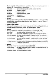
...but stop for all other errors. (Default) All, But Diskette The system boot will stop for any error. Extended Memory The amount of cylinders. Cylinder Number of extended memory. - 43 - If you to None. All, But Keyboard The system boot will not stop for a keyboard ...error but stop . Head Number of sectors. Memory These fields are read-only and are determined by the BIOS POST. Sector Number of heads. Base Memory Also called conventional memory. The following fields display your system. Capacity Approximate capacity of floppy disk...
...but stop for all other errors. (Default) All, But Diskette The system boot will stop for any error. Extended Memory The amount of cylinders. Cylinder Number of extended memory. - 43 - If you to None. All, But Keyboard The system boot will not stop for a keyboard ...error but stop . Head Number of sectors. Memory These fields are read-only and are determined by the BIOS POST. Sector Number of heads. Base Memory Also called conventional memory. The following fields display your system. Capacity Approximate capacity of floppy disk...

Manual
Page 51
Keyboard 98 Press POWER button on the Windows 98 keyboard to turn on the system, enter the password and press . To turn on the system. Memory The system returns to its last known awake state upon the return of the AC power. BIOS Setup PME Event Wake Up Allows the system ...
Keyboard 98 Press POWER button on the Windows 98 keyboard to turn on the system, enter the password and press . To turn on the system. Memory The system returns to its last known awake state upon the return of the AC power. BIOS Setup PME Event Wake Up Allows the system ...
Manual
Page 61
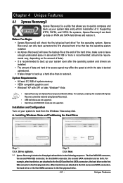
... back up/restore the first physical hard drive that allows you to quickly compress and back up your system data and perform restoration of system memory • VESA compatible graphics card • Windows® XP with Xpress Recovery cannot be restored using Xpress Recovery2. • USB hard drives are not supported...
... back up/restore the first physical hard drive that allows you to quickly compress and back up your system data and perform restoration of system memory • VESA compatible graphics card • Windows® XP with Xpress Recovery cannot be restored using Xpress Recovery2. • USB hard drives are not supported...
Manual
Page 68
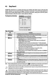
...settings to a new profile (.txt file). • Load allows you set temperature/fan speed alarm. GA-MA770T-UD3/US3 Motherboard - 68 - You can choose the alert sound from a profile. 4-3 EasyTune 6 GIGABYTE's EasyTune 6 is a simple and easy-to-use interface that the item is not configurable or ...Graphics tab allows you to fine-tune their systemrelated information without the need to the hardware components such as CPU, chipset, and memory and reduce the useful life of EasyTune 6, or system instability or other unexpected results may occur. The user-friendly EasyTune 6 interface...
...settings to a new profile (.txt file). • Load allows you set temperature/fan speed alarm. GA-MA770T-UD3/US3 Motherboard - 68 - You can choose the alert sound from a profile. 4-3 EasyTune 6 GIGABYTE's EasyTune 6 is a simple and easy-to-use interface that the item is not configurable or ...Graphics tab allows you to fine-tune their systemrelated information without the need to the hardware components such as CPU, chipset, and memory and reduce the useful life of EasyTune 6, or system instability or other unexpected results may occur. The user-friendly EasyTune 6 interface...

Manual
Page 75
... enter the Delete LD window. To delete an array, press to configure a RAID array. Figure 2 Step 2: Main Menu This is defined.. Step 1: After the POST memory test begins and before the operating system boot begins, look for a message which says "Press to enter the Controller Configuration window. To view controller settings...
... enter the Delete LD window. To delete an array, press to configure a RAID array. Figure 2 Step 2: Main Menu This is defined.. Step 1: After the POST memory test begins and before the operating system boot begins, look for a message which says "Press to enter the Controller Configuration window. To view controller settings...

Manual
Page 91
...short: System boots successfully 1 long, 3 short: Keyboard error 2 short: CMOS setting error 1 long, 9 short: BIOS ROM error 1 long, 1 short: Memory or motherboard error Continuous long beeps: Graphics card not inserted properly 1 long, 2 short: Monitor or graphics card error Continuous short beeps: Power error - 91 ... with power/amplifier. Then install the onboard HD audio driver from the motherboard driver disk or download the audio driver from GIGABYTE's website to show the advanced options. For motherboards that have turned my speaker to enter BIOS Setup during the POST mean...
...short: System boots successfully 1 long, 3 short: Keyboard error 2 short: CMOS setting error 1 long, 9 short: BIOS ROM error 1 long, 1 short: Memory or motherboard error Continuous long beeps: Graphics card not inserted properly 1 long, 2 short: Monitor or graphics card error Continuous short beeps: Power error - 91 ... with power/amplifier. Then install the onboard HD audio driver from the motherboard driver disk or download the audio driver from GIGABYTE's website to show the advanced options. For motherboards that have turned my speaker to enter BIOS Setup during the POST mean...


