
Manual
Page 4
Table of Contents Box Contents...6 Optional Items...6 GA-MA74GM-S2H/GA-MA74GM-S2 Motherboard Layout 7 Block Diagram...8 Chapter 1 Hardware Installation 9 1-1 Installation Precautions 9 1-2 Product Specifications 10 1-3 Installing the CPU and CPU Cooler 13 1-3-1 Installing the CPU 13 1-3-2 Installing the CPU Cooler 15 1-4 Installing the Memory 16 1-4-1 Dual Channel Memory Configuration 16 1-4-2 Installing a Memory 17 1-5 Installing an Expansion Card 18 1-6 Back Panel...
Table of Contents Box Contents...6 Optional Items...6 GA-MA74GM-S2H/GA-MA74GM-S2 Motherboard Layout 7 Block Diagram...8 Chapter 1 Hardware Installation 9 1-1 Installation Precautions 9 1-2 Product Specifications 10 1-3 Installing the CPU and CPU Cooler 13 1-3-1 Installing the CPU 13 1-3-2 Installing the CPU Cooler 15 1-4 Installing the Memory 16 1-4-1 Dual Channel Memory Configuration 16 1-4-2 Installing a Memory 17 1-5 Installing an Expansion Card 18 1-6 Back Panel...

Manual
Page 8
Block Diagram PCIe CLK (100 MHz) 1 PCI Express x16 AM3/AM2+/AM2 CPU CPU CLK+/- (200 MHz) DDR2 1066/800/667/533 MHz Dual Channel Memory Hyper Transport Bus PCI Express x16 GFX CLK (100 MHz) PCI Express Bus ... BIOS Floppy COM Port 2 PCI PS/2 KB or Mouse MIC Line Out Line In S/PDIF In S/PDIF Out PCI CLK (33 MHz) j (Note) Only for GA-MA74GM-S2H Simultaneous output for DVI-D and HDMI is not supported. - 8 -
Block Diagram PCIe CLK (100 MHz) 1 PCI Express x16 AM3/AM2+/AM2 CPU CPU CLK+/- (200 MHz) DDR2 1066/800/667/533 MHz Dual Channel Memory Hyper Transport Bus PCI Express x16 GFX CLK (100 MHz) PCI Express Bus ... BIOS Floppy COM Port 2 PCI PS/2 KB or Mouse MIC Line Out Line In S/PDIF In S/PDIF Out PCI CLK (33 MHz) j (Note) Only for GA-MA74GM-S2H Simultaneous output for DVI-D and HDMI is not supported. - 8 -

Manual
Page 9
... any metal leads or connectors. • It is best to wear an electrostatic discharge (ESD) wrist strap when handling electronic com- ponents such as a motherboard, CPU or memory. Hardware Installation These stickers are required for warranty validation. • Always remove the AC power by your hardware components are connected. • To...
... any metal leads or connectors. • It is best to wear an electrostatic discharge (ESD) wrist strap when handling electronic com- ponents such as a motherboard, CPU or memory. Hardware Installation These stickers are required for warranty validation. • Always remove the AC power by your hardware components are connected. • To...

Manual
Page 10
... Phenom™ II processor/ AMD Phenom™ processor/ AMD Athlon™ II processor/ AMD Athlon™ processor/ AMD Sempron™ processor (Go to GIGABYTE's website for the latest CPU support list.) Hyper Transport Bus 2000 MT/s Chipset Memory Onboard Graphics Audio ...Dual channel memory architecture Support for DDR2 1066/800/667/533 MHz memory modules Support for non-ECC memory modules (Go to GIGABYTE's website for GA-MA74GM-S2H Hardware Installation - 10 -
... Phenom™ II processor/ AMD Phenom™ processor/ AMD Athlon™ II processor/ AMD Athlon™ processor/ AMD Sempron™ processor (Go to GIGABYTE's website for the latest CPU support list.) Hyper Transport Bus 2000 MT/s Chipset Memory Onboard Graphics Audio ...Dual channel memory architecture Support for DDR2 1066/800/667/533 MHz memory modules Support for non-ECC memory modules (Go to GIGABYTE's website for GA-MA74GM-S2H Hardware Installation - 10 -
Manual
Page 11
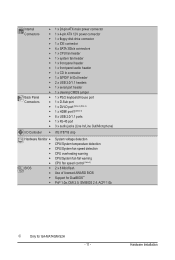
...pin ATX main power connector w 1 x 4-pin ATX 12V power connector w 1 x floppy disk drive connector w 1 x IDE connector w 4 x SATA 3Gb/s connectors w 1 x CPU fan header w 1 x system fan header w 1 x front panel header w 1 x front panel audio header w 1 x CD In connector w 1 x S/PDIF In/Out header ...detection CPU/System temperature detection CPU/System fan speed detection CPU overheating warning CPU/System fan fail warning CPU fan speed control (Note 5) 2 x 8 Mbit flash Use of licensed AWARD BIOS Support for DualBIOS™ PnP 1.0a, DMI 2.0, SM BIOS 2.4, ACPI 1.0b j Only for GA-MA74GM-S2H...
...pin ATX main power connector w 1 x 4-pin ATX 12V power connector w 1 x floppy disk drive connector w 1 x IDE connector w 4 x SATA 3Gb/s connectors w 1 x CPU fan header w 1 x system fan header w 1 x front panel header w 1 x front panel audio header w 1 x CD In connector w 1 x S/PDIF In/Out header ...detection CPU/System temperature detection CPU/System fan speed detection CPU overheating warning CPU/System fan fail warning CPU fan speed control (Note 5) 2 x 8 Mbit flash Use of licensed AWARD BIOS Support for DualBIOS™ PnP 1.0a, DMI 2.0, SM BIOS 2.4, ACPI 1.0b j Only for GA-MA74GM-S2H...
Manual
Page 12
... 7.1-channel audio, you have to use an HD front panel audio module and enable themulti-channel audio feature through the audio driver. (Note 5) Whether the CPU fan speed control function is supported will depend on the CPU cooler you install. (Note 6) Available functions in EasyTune may differ by motherboard model.
... 7.1-channel audio, you have to use an HD front panel audio module and enable themulti-channel audio feature through the audio driver. (Note 5) Whether the CPU fan speed control function is supported will depend on the CPU cooler you install. (Note 6) Available functions in EasyTune may differ by motherboard model.
Manual
Page 13
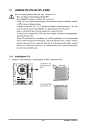
...meet the standard requirements for the latest CPU support list.) • Always turn on the computer if the CPU cooler is not recommended that the motherboard supports the CPU. (Go to GIGABYTE's website for the peripherals. 1-3 Installing the CPU and CPU Cooler Read the following guidelines before ...you begin to install the CPU: • Make sure that the system...
...meet the standard requirements for the latest CPU support list.) • Always turn on the computer if the CPU cooler is not recommended that the motherboard supports the CPU. (Go to GIGABYTE's website for the peripherals. 1-3 Installing the CPU and CPU Cooler Read the following guidelines before ...you begin to install the CPU: • Make sure that the system...
Manual
Page 14
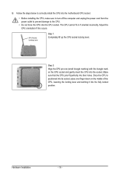
... CPU socket and gently insert the CPU into the fully locked position. CPU Socket Locking Lever Step 1: Completely lift up the CPU socket locking lever. Adjust the CPU orientation if this occurs. Hardware Installation - 14 - B. Make sure that the CPU pins fit perfectly into the CPU socket. Once the CPU ...with the triangle mark on the middle of the CPU, lowering the locking lever and latching it into the socket. Follow the steps below to correctly install the CPU into the motherboard CPU socket. • Before installing the CPU, make sure to turn off the computer and unplug...
... CPU socket and gently insert the CPU into the fully locked position. CPU Socket Locking Lever Step 1: Completely lift up the CPU socket locking lever. Adjust the CPU orientation if this occurs. Hardware Installation - 14 - B. Make sure that the CPU pins fit perfectly into the CPU socket. Once the CPU ...with the triangle mark on the middle of the CPU, lowering the locking lever and latching it into the socket. Follow the steps below to correctly install the CPU into the motherboard CPU socket. • Before installing the CPU, make sure to turn off the computer and unplug...

Manual
Page 15
....) Step 1: Apply an even and thin layer of thermal grease on the surface of the installed CPU. Hardware Installation 1-3-2 Installing the CPU Cooler Follow the steps below to correctly install the CPU cooler on the CPU. (The following procedure uses the GIGABYTE cooler as the picture above shows) to lock into place. (Refer to your...
....) Step 1: Apply an even and thin layer of thermal grease on the surface of the installed CPU. Hardware Installation 1-3-2 Installing the CPU Cooler Follow the steps below to correctly install the CPU cooler on the CPU. (The following procedure uses the GIGABYTE cooler as the picture above shows) to lock into place. (Refer to your...
Manual
Page 16
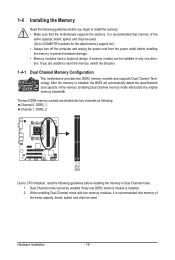
... Memory Read the following guidelines before you are divided into two channels as following: Channel 0: DDR2_1 Channel 1: DDR2_2 DDR2_1 DDR2_2 Due to CPU limitation, read the following guidelines before installing the memory to prevent hardware damage. • Memory modules have a foolproof design. When enabling... the same capacity, brand, speed, and chips be installed in Dual Channel mode. 1. The two DDR2 memory sockets are unable to GIGABYTE's website for the latest memory support list.) • Always turn off the computer and unplug the power cord from the power outlet ...
... Memory Read the following guidelines before you are divided into two channels as following: Channel 0: DDR2_1 Channel 1: DDR2_2 DDR2_1 DDR2_2 Due to CPU limitation, read the following guidelines before installing the memory to prevent hardware damage. • Memory modules have a foolproof design. When enabling... the same capacity, brand, speed, and chips be installed in Dual Channel mode. 1. The two DDR2 memory sockets are unable to GIGABYTE's website for the latest memory support list.) • Always turn off the computer and unplug the power cord from the power outlet ...
Manual
Page 20
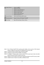
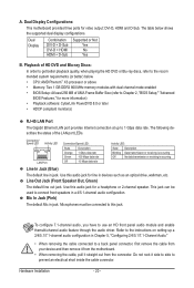
... following describes the states of UMA Frame Buffer Size (refer to Chapter 2, "BIOS Setup," "Advanced BIOS Features," for line in jack. The table below . • CPU: AMD Phenom™ X3 processor or above • Memory: Two 1 GB DDR2 800 MHz memory modules with dual channel mode enabled • BIOS Setup: At...
... following describes the states of UMA Frame Buffer Size (refer to Chapter 2, "BIOS Setup," "Advanced BIOS Features," for line in jack. The table below . • CPU: AMD Phenom™ X3 processor or above • Memory: Two 1 GB DDR2 800 MHz memory modules with dual channel mode enabled • BIOS Setup: At...
Manual
Page 22
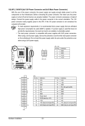
Connect the power supply cable to the CPU. If the 12V power connector is not connected, the computer will not start. • To meet expansion requirements, it is compatible with power supplies with ...
Connect the power supply cable to the CPU. If the 12V power connector is not connected, the computer will not start. • To meet expansion requirements, it is compatible with power supplies with ...

Manual
Page 23
...sure to connect it is used to prevent your CPU and system from overheating. 3/4) CPU_FAN/SYS_FAN (Fan Headers) The motherboard has a 4-pin CPU fan header (CPU_FAN) and a 3-pin (SYS_FAN) system fan headers. The motherboard supports CPU fan speed control, which requires the use of different... color. Overheating may result in the correct orientation (the black connector wire is typically designated by a stripe of a CPU fan with fan speed control design. For purchasing ...
...sure to connect it is used to prevent your CPU and system from overheating. 3/4) CPU_FAN/SYS_FAN (Fan Headers) The motherboard has a 4-pin CPU fan header (CPU_FAN) and a 3-pin (SYS_FAN) system fan headers. The motherboard supports CPU fan speed control, which requires the use of different... color. Overheating may result in the correct orientation (the black connector wire is typically designated by a stripe of a CPU fan with fan speed control design. For purchasing ...
Manual
Page 33
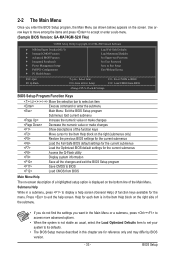
.... - 33 - BIOS Setup Use arrow keys to move among the items and press to accept or enter a sub-menu. (Sample BIOS Version: GA-MA74GM-S2H FAa) CMOS Setup Utility-Copyright (C) 1984-2009 Award Software MB Intelligent Tweaker(M.I.T.) Standard CMOS Features Advanced BIOS Features ...Supervisor Password Set User Password Save & Exit Setup Exit Without Saving ESC: Quit F8: Q-Flash Select Item F10: Save & Exit Setup Change CPU's Clock & Voltage F11: Save CMOS to BIOS F12: Load CMOS from BIOS Main Menu Help The on-screen description of a highlighted setup...
.... - 33 - BIOS Setup Use arrow keys to move among the items and press to accept or enter a sub-menu. (Sample BIOS Version: GA-MA74GM-S2H FAa) CMOS Setup Utility-Copyright (C) 1984-2009 Award Software MB Intelligent Tweaker(M.I.T.) Standard CMOS Features Advanced BIOS Features ...Supervisor Password Set User Password Save & Exit Setup Exit Without Saving ESC: Quit F8: Q-Flash Select Item F10: Save & Exit Setup Change CPU's Clock & Voltage F11: Save CMOS to BIOS F12: Load CMOS from BIOS Main Menu Help The on-screen description of a highlighted setup...

Manual
Page 34
...that stop the system boot, etc. Advanced BIOS Features Use this menu to configure the device boot order, advanced features available on the CPU, and the primary display adapter. Integrated Peripherals Use this menu to configure all peripheral devices, such as IDE, SATA, USB, integrated...Use this menu to configure the system's PCI & PnP resources. PC Health Status Use this menu to see information about autodetected system/CPU temperature, system voltage and fan speed, etc. Load Fail-Safe Defaults Fail-Safe defaults are factory settings for the most stable, ...
...that stop the system boot, etc. Advanced BIOS Features Use this menu to configure the device boot order, advanced features available on the CPU, and the primary display adapter. Integrated Peripherals Use this menu to configure all peripheral devices, such as IDE, SATA, USB, integrated...Use this menu to configure the system's PCI & PnP resources. PC Health Status Use this menu to see information about autodetected system/CPU temperature, system voltage and fan speed, etc. Load Fail-Safe Defaults Fail-Safe defaults are factory settings for the most stable, ...
Manual
Page 35
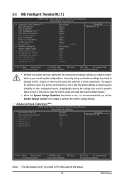
... 1984-2009 Award Software MB Intelligent Tweaker(M.I.T.) } Advanced Clock Calibration (Note) HT Link Frequency CPU Clock Ratio CPU NorthBridge Freq. (Note) CPU Host Clock Control x CPU Frequency(MHz) PCIE Clock(MHz) VGA Core Clock(MHz) Set Memory Clock x Memory Clock }... DRAM Configuration System Voltage Control x DDR2 Voltage Control x NorthBridge Volt Control x SouthBridge Volt Control x CPU NB VID Control x CPU Voltage Control Normal CPU Vcore [Press Enter] [Auto] [Auto] [Auto] [Auto] 200 [Auto] [400] [Auto] x3.33 ...
... 1984-2009 Award Software MB Intelligent Tweaker(M.I.T.) } Advanced Clock Calibration (Note) HT Link Frequency CPU Clock Ratio CPU NorthBridge Freq. (Note) CPU Host Clock Control x CPU Frequency(MHz) PCIE Clock(MHz) VGA Core Clock(MHz) Set Memory Clock x Memory Clock }... DRAM Configuration System Voltage Control x DDR2 Voltage Control x NorthBridge Volt Control x SouthBridge Volt Control x CPU NB VID Control x CPU Voltage Control Normal CPU Vcore [Press Enter] [Auto] [Auto] [Auto] [Auto] 200 [Auto] [400] [Auto] x3.33 ...
Manual
Page 36
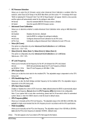
... Auto All Cores Lets the BIOS to configure the settings to defaults. BIOS Setup - 36 - EC Firmware Selection Allows you to manually set the CPU host frequency. Don't Turn Off Or Reset System" will automatically adjust the HT Link Frequency. (Default) 200 MHz~1 GHz Sets HT Link Frequency to... automated system reboot, or clear the CMOS values to reset the board to alter the North Bridge controller frequency for the HT Link between the CPU and chipset. Options are : -12%~+12%. Value (Core 0), Value (Core 1), Value (Core 2), Value (Core 3) This option is configurable only when Advanced ...
... Auto All Cores Lets the BIOS to configure the settings to defaults. BIOS Setup - 36 - EC Firmware Selection Allows you to manually set the CPU host frequency. Don't Turn Off Or Reset System" will automatically adjust the HT Link Frequency. (Default) 200 MHz~1 GHz Sets HT Link Frequency to... automated system reboot, or clear the CMOS values to reset the board to alter the North Bridge controller frequency for the HT Link between the CPU and chipset. Options are : -12%~+12%. Value (Core 0), Value (Core 1), Value (Core 2), Value (Core 3) This option is configurable only when Advanced ...
Manual
Page 37
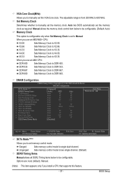
...) Allows you to set memory control mode. Auto lets BIOS automatically set the memory clock. When you use an AM2 CPU: DDR 400 Sets Memory Clock to X2.00. When you install a CPU that supports this feature. - 37 - Options are: Auto (default), Manual. (Note) This item appears only if you use an...
...) Allows you to set memory control mode. Auto lets BIOS automatically set the memory clock. When you use an AM2 CPU: DDR 400 Sets Memory Clock to X2.00. When you install a CPU that supports this feature. - 37 - Options are: Auto (default), Manual. (Note) This item appears only if you use an...
Manual
Page 39
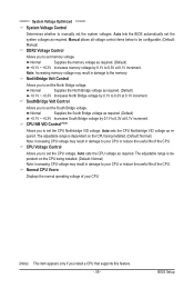
...Auto lets the BIOS automatically set the system voltages as required. (Default) +0.1V ~ +0.3V Increases memory voltage by 0.1V to set the CPU Northbridge VID voltage. Note: Increasing memory voltage may result in damage to 0.3V at 0.1V increment. NorthBridge Volt Control Allows you to set ...Normal Supplies the South Bridge voltage as required. (Default) +0.1V ~ +0.3V Increases North Bridge voltage by 0.1V to your CPU or reduce the useful life of the CPU. Normal Supplies the North Bridge voltage as required. (Default) +0.1V ~ +0.3V Increases South Bridge voltage by 0.1V to your...
...Auto lets the BIOS automatically set the system voltages as required. (Default) +0.1V ~ +0.3V Increases memory voltage by 0.1V to set the CPU Northbridge VID voltage. Note: Increasing memory voltage may result in damage to 0.3V at 0.1V increment. NorthBridge Volt Control Allows you to set ...Normal Supplies the South Bridge voltage as required. (Default) +0.1V ~ +0.3V Increases North Bridge voltage by 0.1V to your CPU or reduce the useful life of the CPU. Normal Supplies the North Bridge voltage as required. (Default) +0.1V ~ +0.3V Increases South Bridge voltage by 0.1V to your...

Manual
Page 42
... Disabled. j Only for entering the BIOS Setup program. (Default) System A password is required every time the system boots, or only when you install a CPU that supports this item, set the password(s) under the Set Supervisor/User Password item in independent partitions. Press to run multiple operating systems and applications... or down arrow key to select a device and press to move it up or down on the list. Setup A password is only required for GA-MA74GM-S2H. (Note) This item appears only if you enter BIOS Setup. Use the up or down arrow key to select a hard drive, then...
... Disabled. j Only for entering the BIOS Setup program. (Default) System A password is required every time the system boots, or only when you install a CPU that supports this item, set the password(s) under the Set Supervisor/User Password item in independent partitions. Press to run multiple operating systems and applications... or down arrow key to select a device and press to move it up or down on the list. Setup A password is only required for GA-MA74GM-S2H. (Note) This item appears only if you enter BIOS Setup. Use the up or down arrow key to select a hard drive, then...


