Manual
Page 26
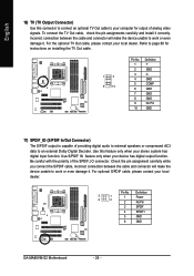
... your local dealer. For optional S/PDIF cable, please contact your local dealer. Definition 5 1 6 2 1 Power 2 No Pin 3 SPDIF 4 SPDIFI 5 GND 6 GND GA-MA69VM-S2 Motherboard - 26 - Be careful with the polarity of analog video signals. Use S/PDIF IN feature only when your computer for instructions on installing the TV Out cable. 1 2 9 10 Pin No. 1 2 3 4 5 6 7 8 9 10...
... your local dealer. For optional S/PDIF cable, please contact your local dealer. Definition 5 1 6 2 1 Power 2 No Pin 3 SPDIF 4 SPDIFI 5 GND 6 GND GA-MA69VM-S2 Motherboard - 26 - Be careful with the polarity of analog video signals. Use S/PDIF IN feature only when your computer for instructions on installing the TV Out cable. 1 2 9 10 Pin No. 1 2 3 4 5 6 7 8 9 10...

Manual
Page 69
... Connects to the TV output connector Follow the steps below to install theTV Out Cable: Step 1: Secure the TV Out cable to output the analog video signals (Note) . Step 2: Connect TV Out cable connector to the TV Out cable. • Insert the TV Out cable securely into the ...your system and the power switch on the motherboard (refer to page 26). English 4-1-5 Installation of analog video signals. S-Video Out OR NTSC / PAL TV Projector AV Out OR NTSC / PAL TV Projector (Note): The S-Video Out and AV Out cannot be used at the same time. - 69 - Hardware Installation •...
... Connects to the TV output connector Follow the steps below to install theTV Out Cable: Step 1: Secure the TV Out cable to output the analog video signals (Note) . Step 2: Connect TV Out cable connector to the TV Out cable. • Insert the TV Out cable securely into the ...your system and the power switch on the motherboard (refer to page 26). English 4-1-5 Installation of analog video signals. S-Video Out OR NTSC / PAL TV Projector AV Out OR NTSC / PAL TV Projector (Note): The S-Video Out and AV Out cannot be used at the same time. - 69 - Hardware Installation •...

Manual
Page 70
... Previous Values +/-/PU/PD: Value F10: Save F6: Fail-Safe Defaults ESC: Exit F1: General Help F7: Optimized Defaults Step 3: Set Video Display Devices under the IGX Configuration submenu to enter the submenu. CMOS Setup Utility-Copyright (C) 1984-2007 Award Software IGX Configuration IGX Clock Mode x...PU/PD: Value F10: Save F6: Fail-Safe Defaults ESC: Exit F1: General Help F7: Optimized Defaults Step 4:Save and exit BIOS Setup. GA-M69VM-S2 Motherboard - 70 - English Enabling the TV Out Function Method 1: Throuth the BIOS Setup program Step 1: In BIOS Setup, press + to access ...
... Previous Values +/-/PU/PD: Value F10: Save F6: Fail-Safe Defaults ESC: Exit F1: General Help F7: Optimized Defaults Step 3: Set Video Display Devices under the IGX Configuration submenu to enter the submenu. CMOS Setup Utility-Copyright (C) 1984-2007 Award Software IGX Configuration IGX Clock Mode x...PU/PD: Value F10: Save F6: Fail-Safe Defaults ESC: Exit F1: General Help F7: Optimized Defaults Step 4:Save and exit BIOS Setup. GA-M69VM-S2 Motherboard - 70 - English Enabling the TV Out Function Method 1: Throuth the BIOS Setup program Step 1: In BIOS Setup, press + to access ...


