Manual
Page 4
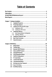
Table of Contents Box Contents ...6 OptionalItems...6 GA-M61PME-S2 Motherboard Layout 7 Block Diagram...8 Chapter 1 Hardware Installation 9 1-1 Installation Precautions 9 1-2 Product Specifications 10 1-3 Installing the CPU and CPU Cooler 12 1-3-1 Installing the CPU 12 1-3-2 Installing the CPU Cooler 14 1-4 Installing the Memory 15 1-4-1 Dual Channel Memory Configuration 15 1-4-2 Installing a Memory 16 1-5 Installing an Expansion Card 17 1-6 Back Panel Connectors...
Table of Contents Box Contents ...6 OptionalItems...6 GA-M61PME-S2 Motherboard Layout 7 Block Diagram...8 Chapter 1 Hardware Installation 9 1-1 Installation Precautions 9 1-2 Product Specifications 10 1-3 Installing the CPU and CPU Cooler 12 1-3-1 Installing the CPU 12 1-3-2 Installing the CPU Cooler 14 1-4 Installing the Memory 15 1-4-1 Dual Channel Memory Configuration 15 1-4-2 Installing a Memory 16 1-5 Installing an Expansion Card 17 1-6 Back Panel Connectors...
Manual
Page 8
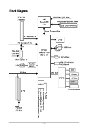
Block Diagram PCIe CLK (100 MHz) AMD Socket AM2 CPU CPU CLK+/-(200 MHz) DDR2 800/667/533 MHz DIMM Dual Channel Memory Hyper Transport Bus PCI Express x16 PCI Express x1 Bus D-Sub x1 PCIe CLK (100 MHz) 1 PCI Express x1 LAN RJ45 Realtek 8201CL NVIDIA® GeForce 6100/ nForce 430 8 USB Ports 2 SATA 3Gb/s ATA-133/100/66/33 IDE Channel PCI Bus LPC BUS BIOS Floppy IT8716 LPT Port CODEC COM Port 2 PCI PS/2 KB/Mouse MIC (Center/Subwoofer Speaker Out) Line-Out (Front Speaker Out) Line-In (Rear Speaker Out) SPDIF Out PCI CLK (33 MHz) - 8 -
Block Diagram PCIe CLK (100 MHz) AMD Socket AM2 CPU CPU CLK+/-(200 MHz) DDR2 800/667/533 MHz DIMM Dual Channel Memory Hyper Transport Bus PCI Express x16 PCI Express x1 Bus D-Sub x1 PCIe CLK (100 MHz) 1 PCI Express x1 LAN RJ45 Realtek 8201CL NVIDIA® GeForce 6100/ nForce 430 8 USB Ports 2 SATA 3Gb/s ATA-133/100/66/33 IDE Channel PCI Bus LPC BUS BIOS Floppy IT8716 LPT Port CODEC COM Port 2 PCI PS/2 KB/Mouse MIC (Center/Subwoofer Speaker Out) Line-Out (Front Speaker Out) Line-In (Rear Speaker Out) SPDIF Out PCI CLK (33 MHz) - 8 -
Manual
Page 9
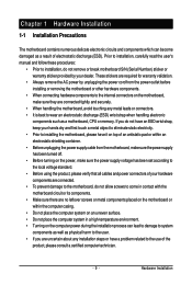
... 1-1 Installation Precautions The motherboard contains numerous delicate electronic circuits and components which can lead to damage to system components as well as a motherboard, CPU or memory.
... 1-1 Installation Precautions The motherboard contains numerous delicate electronic circuits and components which can lead to damage to system components as well as a motherboard, CPU or memory.
Manual
Page 10
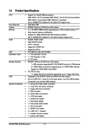
.../nForce 430 chipset Memory 2 x 1.8V DDR2 DIMM sockets supporting up to 8 GB of system memory (Note 1) Dual channel memory architecture Support for DDR2 800/667/533 MHz memory modules (Go to GIGABYTE's website for the latest memory support list.) Audio...CD In connector 1 x S/PDIF Out header 2 x USB 2.0/1.1 headers 1 x chassis intrusion header 1 x power LED header GA-M61PME-S2 Motherboard - 10 - Support for CD In LAN RTL 8201CL chip (10/100 Mbit) Expansion Slots 1 x PCI Express x16 slot 1 x...
.../nForce 430 chipset Memory 2 x 1.8V DDR2 DIMM sockets supporting up to 8 GB of system memory (Note 1) Dual channel memory architecture Support for DDR2 800/667/533 MHz memory modules (Go to GIGABYTE's website for the latest memory support list.) Audio...CD In connector 1 x S/PDIF Out header 2 x USB 2.0/1.1 headers 1 x chassis intrusion header 1 x power LED header GA-M61PME-S2 Motherboard - 10 - Support for CD In LAN RTL 8201CL chip (10/100 Mbit) Expansion Slots 1 x PCI Express x16 slot 1 x...
Manual
Page 11
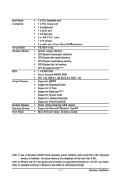
... form factor; 24.4cm x 22.5cm (Note 1) Due to Windows Vista/XP 32-bit operating system limitation, when more than 4 GB of physical memory is installed, the actual memory size displayed will be less than 4 GB. (Note 2) Whether the CPU fan speed control function is supported will depend on the CPU you...
... form factor; 24.4cm x 22.5cm (Note 1) Due to Windows Vista/XP 32-bit operating system limitation, when more than 4 GB of physical memory is installed, the actual memory size displayed will be less than 4 GB. (Note 2) Whether the CPU fan speed control function is supported will depend on the CPU you...

Manual
Page 12
...in accordance with the CPU specifications. mended that the motherboard supports the CPU. (Go to your hardware specifications including the CPU, graphics card, memory, hard drive, etc. 1-3-1 Installing the CPU A. If you begin to install the CPU: • Make sure that the system bus frequency...GIGABYTE's website for the peripherals. A Small Triangle Mark Denotes Pin One of the CPU. It is not installed, otherwise overheating and damage of the CPU socket and the CPU. Locate the pin one of the Socket AM2 CPU Socket A Small Triangle Marking Denotes CPU Pin One AM2 CPU GA-M61PME-S2...
...in accordance with the CPU specifications. mended that the motherboard supports the CPU. (Go to your hardware specifications including the CPU, graphics card, memory, hard drive, etc. 1-3-1 Installing the CPU A. If you begin to install the CPU: • Make sure that the system bus frequency...GIGABYTE's website for the peripherals. A Small Triangle Mark Denotes Pin One of the CPU. It is not installed, otherwise overheating and damage of the CPU socket and the CPU. Locate the pin one of the Socket AM2 CPU Socket A Small Triangle Marking Denotes CPU Pin One AM2 CPU GA-M61PME-S2...
Manual
Page 15
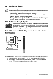
... of the same capacity, brand, speed, and chips be used . (Go to GIGABYTE's website for the latest memory support list.) • Always turn off the computer and unplug the power cord from the power outlet before installing the memory in only one DDR2 memory module is installed. 2. When enabling Dual Channel mode with two...
... of the same capacity, brand, speed, and chips be used . (Go to GIGABYTE's website for the latest memory support list.) • Always turn off the computer and unplug the power cord from the power outlet before installing the memory in only one DDR2 memory module is installed. 2. When enabling Dual Channel mode with two...

Manual
Page 16
... Note the orientation of the memory socket. Spread the retaining clips at both ends of the memory module. Notch DDR2 DIMM A DDR2 memory module has a notch, so it vertically into place when the memory module is securely inserted. GA-M61PME-S2 Motherboard - 16 - DDR2 DIMMs... are not compatible to DDR DIMMs. Be sure to the memory module. Place the memory module on this motherboard. 1-4-2 Installing a Memory Before installing a memory module , make sure to turn...
... Note the orientation of the memory socket. Spread the retaining clips at both ends of the memory module. Notch DDR2 DIMM A DDR2 memory module has a notch, so it vertically into place when the memory module is securely inserted. GA-M61PME-S2 Motherboard - 16 - DDR2 DIMMs... are not compatible to DDR DIMMs. Be sure to the memory module. Place the memory module on this motherboard. 1-4-2 Installing a Memory Before installing a memory module , make sure to turn...
Manual
Page 33
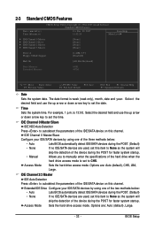
... IDE Channel 2 Master IDE Channel 3 Master [None] [None] [None] [None] Drive A Floppy 3 Mode Support [1.44M, 3.5"] [Disabled] Halt On [All, But Keyboard] Base Memory Extended Memory 640K 447M Move Enter: Select F5: Previous Values +/-/PU/PD: Value F10: Save F6: Fail-Safe Default ESC: Exit F1: General Help F7: Optimized Defaults...
... IDE Channel 2 Master IDE Channel 3 Master [None] [None] [None] [None] Drive A Floppy 3 Mode Support [1.44M, 3.5"] [Disabled] Halt On [All, But Keyboard] Base Memory Extended Memory 640K 447M Move Enter: Select F5: Previous Values +/-/PU/PD: Value F10: Save F6: Fail-Safe Default ESC: Exit F1: General Help F7: Optimized Defaults...
Manual
Page 34
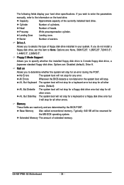
... for any error. GA-M61PME-S2 Motherboard - 34 - Options are determined by the BIOS POST. Halt on the hard drive. All Errors Whenever the BIOS detects a non-fatal error the system boot will not stop for the MS-DOS operating system. Memory These fields are read...only and are : None, 360K/5.25", 1.2M/5.25", 720K/3.5", 1.44M/3.5", 2.88M/3.5". Precomp Write precompensation cylinder. Extended Memory The amount of heads. Head Number of extended memory. Options are: Disabled (default), Drive A. All, But Keyboard The system boot will not stop for a floppy disk...
... for any error. GA-M61PME-S2 Motherboard - 34 - Options are determined by the BIOS POST. Halt on the hard drive. All Errors Whenever the BIOS detects a non-fatal error the system boot will not stop for the MS-DOS operating system. Memory These fields are read...only and are : None, 360K/5.25", 1.2M/5.25", 720K/3.5", 1.44M/3.5", 2.88M/3.5". Precomp Write precompensation cylinder. Extended Memory The amount of heads. Head Number of extended memory. Options are: Disabled (default), Drive A. All, But Keyboard The system boot will not stop for a floppy disk...
Manual
Page 36
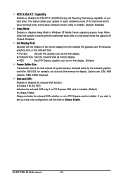
...for example, will use only this item to issue warnings when a third party hardware monitor utility is the total amount of system memory allocated solely for display. Capability Enables or disables the S.M.A.R.T. (Self Monitoring and Reporting Technology) capability of your system to report ...wish to silently perform unattended tasks while in Windows XP Media Center operating system. GA-M61PME-S2 Motherboard - 36 - Away Mode allows the system to set up a dual view configuration, set this memory for the onboard graphics controller. PCI Slot Sets the PCI graphics card as ...
...for example, will use only this item to issue warnings when a third party hardware monitor utility is the total amount of system memory allocated solely for display. Capability Enables or disables the S.M.A.R.T. (Self Monitoring and Reporting Technology) capability of your system to report ...wish to silently perform unattended tasks while in Windows XP Media Center operating system. GA-M61PME-S2 Motherboard - 36 - Away Mode allows the system to set up a dual view configuration, set this memory for the onboard graphics controller. PCI Slot Sets the PCI graphics card as ...

Manual
Page 37
... Setup 2-5 Integrated Peripherals CMOS Setup Utility-Copyright (C) 1984-2007 Award Software Integrated Peripherals On-Chip IDE Channel NV SATA Controller IDE Prefetch Mode USB Memory Type Serial-ATA RAID Config Onboard Audio Function On-Chip MAC Lan Onboard LAN Boot ROM Onboard Serial Port 1 Onboard Parallel Port Parallel Port... ESC: Exit F1: General Help F7: Optimized Defaults - 37 - Enabled activates the IDE prefetch buffer to enhance hard drive performance. (Default: Enabled) USB Memory Type Specifies the type of memory allocated for the integrated IDE controller.
... Setup 2-5 Integrated Peripherals CMOS Setup Utility-Copyright (C) 1984-2007 Award Software Integrated Peripherals On-Chip IDE Channel NV SATA Controller IDE Prefetch Mode USB Memory Type Serial-ATA RAID Config Onboard Audio Function On-Chip MAC Lan Onboard LAN Boot ROM Onboard Serial Port 1 Onboard Parallel Port Parallel Port... ESC: Exit F1: General Help F7: Optimized Defaults - 37 - Enabled activates the IDE prefetch buffer to enhance hard drive performance. (Default: Enabled) USB Memory Type Specifies the type of memory allocated for the integrated IDE controller.
Manual
Page 53
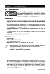
... or later • Xpress Recovery and Xpress Recovery2 are not supported. System Requirements: • Intel® x86 platform • At least 64 MB of system memory • VESA compatible graphics card • Windows® 2000 with Xpress Recovery cannot be restored using Xpress Recovery2. • USB hard drives are not supported...
... or later • Xpress Recovery and Xpress Recovery2 are not supported. System Requirements: • Intel® x86 platform • At least 64 MB of system memory • VESA compatible graphics card • Windows® 2000 with Xpress Recovery cannot be restored using Xpress Recovery2. • USB hard drives are not supported...
Manual
Page 63
... overclock/overvoltage may result in EasyTune 5 may provide optimizations for CPU and memory, enhancing the performance of EasyTune 5, or system instability or other unexpected results may occur. (Note 1) Available functions in damage to enter the BIOS Setup program. Unique Features C.I.A./M.I .B. GIGABYTE Logo 10. OVERCLOCKING 2. EasyTune 5 provides the following functions (Note 1): overclocking/overvoltage...
... overclock/overvoltage may result in EasyTune 5 may provide optimizations for CPU and memory, enhancing the performance of EasyTune 5, or system instability or other unexpected results may occur. (Note 1) Available functions in damage to enter the BIOS Setup program. Unique Features C.I.A./M.I .B. GIGABYTE Logo 10. OVERCLOCKING 2. EasyTune 5 provides the following functions (Note 1): overclocking/overvoltage...

Manual
Page 64
... up your computer's performance. Under Space to reserve for system speed, set the amount of memory space to use for ReadyBoost acceleration is one to three times the amount of memory to use for ReadyBoost using the slider or spin box. 4-4 Windows Vista ReadyBoost Windows ReadyBoost... allows you to use flash memory on a Windows Vista certified USB flash drive to boost your computer. Step 2: In the ReadyBoost tab, select Use this device. GA-M61PME-S2 Motherboard - 64 - Right-click on ReadyBoost. • The USB flash drive...
... up your computer's performance. Under Space to reserve for system speed, set the amount of memory space to use for ReadyBoost acceleration is one to three times the amount of memory to use for ReadyBoost using the slider or spin box. 4-4 Windows Vista ReadyBoost Windows ReadyBoost... allows you to use flash memory on a Windows Vista certified USB flash drive to boost your computer. Step 2: In the ReadyBoost tab, select Use this device. GA-M61PME-S2 Motherboard - 64 - Right-click on ReadyBoost. • The USB flash drive...
Manual
Page 66
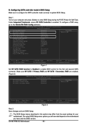
... and second SATA connector. CMOS Setup Utility-Copyright (C) 1984-2007 Award Software Integrated Peripherals On-Chip IDE Channel NV SATA Controller IDE Prefetch Mode USB Memory Type Serial-ATA RAID Config Onboard Audio Function On-Chip MAC Lan Onboard LAN Boot ROM Onboard Serial Port 1 Onboard Parallel Port Parallel Port... see shall depend on your motherboard. Configuring SATA controller mode in system BIOS Setup. Step 1: Turn on the motherboard you have and the BIOS version. GA-M61PME-S2 Motherboard - 66 -
... and second SATA connector. CMOS Setup Utility-Copyright (C) 1984-2007 Award Software Integrated Peripherals On-Chip IDE Channel NV SATA Controller IDE Prefetch Mode USB Memory Type Serial-ATA RAID Config Onboard Audio Function On-Chip MAC Lan Onboard LAN Boot ROM Onboard Serial Port 1 Onboard Parallel Port Parallel Port... see shall depend on your motherboard. Configuring SATA controller mode in system BIOS Setup. Step 1: Turn on the motherboard you have and the BIOS version. GA-M61PME-S2 Motherboard - 66 -

Manual
Page 67
... size can be set the striping block size. Appendix Striping block size is highlighted. C. Configuring RAID set the stripe block size. Step 1: After the POST memory test begins and before the operating system boot begins, look for a message which is created. Hit the key to enter RAID setup utility" (Figure 3). Detecting...
... size can be set the striping block size. Appendix Striping block size is highlighted. C. Configuring RAID set the stripe block size. Step 1: After the POST memory test begins and before the operating system boot begins, look for a message which is created. Hit the key to enter RAID setup utility" (Figure 3). Detecting...
Manual
Page 82
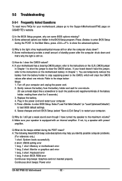
...Setup program, why are hidden in the power cord and restart your speaker is equipped with power/ amplifier. Q:Why is still on GIGABYTE's website. A: The following Award BIOS beep code descriptions may help you identify possible computer problems. (For reference only.) 1 short...setting error 1 long, 1 short: Memory or motherboard error 1 long, 2 short: Monitor or graphics card error 1 long, 3 short: Keyboard error 1 long, 9 short: BIOS ROM error Continuous long beeps: Graphics card not inserted properly Continuous short beeps: Power error GA-M61PME-S2 Motherboard - 82 - In the Main ...
...Setup program, why are hidden in the power cord and restart your speaker is equipped with power/ amplifier. Q:Why is still on GIGABYTE's website. A: The following Award BIOS beep code descriptions may help you identify possible computer problems. (For reference only.) 1 short...setting error 1 long, 1 short: Memory or motherboard error 1 long, 2 short: Monitor or graphics card error 1 long, 3 short: Keyboard error 1 long, 9 short: BIOS ROM error Continuous long beeps: Graphics card not inserted properly Continuous short beeps: Power error GA-M61PME-S2 Motherboard - 82 - In the Main ...

Manual
Page 83
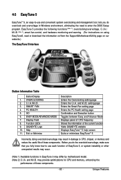
...objects. A (Continued...) - 83 - Turn on the CPU. Press to save changes and exit BIOS Setup. Yes Check if the memory is verified and solved. The problem is installed properly on the memory slot. Remove all peripherals, connecting cables, and power cord etc. Select "Save & Exit Setup" to enter BIOS Setup. Is ...Connect the ATX main power cable and the 12V power cable. Connect the CPU cooler power cable to the CPU securely. No Correctly insert the memory into the memory socket. Select "Load Fail-Safe Defaults" (or "Load Optimized Defaults"). Appendix
...objects. A (Continued...) - 83 - Turn on the CPU. Press to save changes and exit BIOS Setup. Yes Check if the memory is verified and solved. The problem is installed properly on the memory slot. Remove all peripherals, connecting cables, and power cord etc. Select "Save & Exit Setup" to enter BIOS Setup. Is ...Connect the ATX main power cable and the 12V power cable. Connect the CPU cooler power cable to the CPU securely. No Correctly insert the memory into the memory socket. Select "Load Fail-Safe Defaults" (or "Load Optimized Defaults"). Appendix


