
Manual
Page 1
GA-M61P-S3 AMD Socket AM2 Processor Motherboard User's Manual Rev. 1002 12ME-M61PS3-1002R * The WEEE marking on the product indicates this product must not be disposed of with user's other household waste and must be handed over to a designated collection point for the recycling of waste electrical and electronic equipment!! * The WEEE marking applies only in European Union's member states.
GA-M61P-S3 AMD Socket AM2 Processor Motherboard User's Manual Rev. 1002 12ME-M61PS3-1002R * The WEEE marking on the product indicates this product must not be disposed of with user's other household waste and must be handed over to a designated collection point for the recycling of waste electrical and electronic equipment!! * The WEEE marking applies only in European Union's member states.

Manual
Page 2
Motherboard GA-M61P-S3 Dec. 5, 2006 Motherboard GA-M61P-S3 Dec. 5, 2006
Motherboard GA-M61P-S3 Dec. 5, 2006 Motherboard GA-M61P-S3 Dec. 5, 2006

Manual
Page 4
Table of Contents ItemChecklist ...6 OptionalAccessories ...6 GA-M61P-S3 Motherboard Layout 7 Block Diagram ...8 Chapter 1 Hardware Installation 9 1-1 Considerations Prior to Installation 9 1-2 Feature Summary 10 1-3 Installation of the CPU and CPU Cooler 12 1-3-1 Installation of the CPU ...
Table of Contents ItemChecklist ...6 OptionalAccessories ...6 GA-M61P-S3 Motherboard Layout 7 Block Diagram ...8 Chapter 1 Hardware Installation 9 1-1 Considerations Prior to Installation 9 1-2 Feature Summary 10 1-3 Installation of the CPU and CPU Cooler 12 1-3-1 Installation of the CPU ...

Manual
Page 7
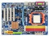
GA-M61P-S3 Motherboard Layout KB_MS Socket AM2 ATX COMA LPT VGA 1394 USB ATX_12V LAN USB AUDIO CPU_FAN F_AUDIO GA-M61P-S3 Realtek 8211 PCIE_1 PCIE_2 CODEC CD_IN SPDIF_IO DDRII_1 DDRII_2 DDRII_3 DDRII_4 IDE PCIE_16 BIOS BATTERY CLR_CMOS nVIDIA® PCI1 GeForce 6100/ nForce 430 PCI2 SATAII3 SATAII2 IT8716 CI COMB PCI3 TSB43AB23 PCI4 F1_1394 F2_1394 FDD SATAII1 F_USB2 F_USB1 F_USB3 SATAII0 SYS_FAN F_PANEL PWR_LED - 7 -
GA-M61P-S3 Motherboard Layout KB_MS Socket AM2 ATX COMA LPT VGA 1394 USB ATX_12V LAN USB AUDIO CPU_FAN F_AUDIO GA-M61P-S3 Realtek 8211 PCIE_1 PCIE_2 CODEC CD_IN SPDIF_IO DDRII_1 DDRII_2 DDRII_3 DDRII_4 IDE PCIE_16 BIOS BATTERY CLR_CMOS nVIDIA® PCI1 GeForce 6100/ nForce 430 PCI2 SATAII3 SATAII2 IT8716 CI COMB PCI3 TSB43AB23 PCI4 F1_1394 F2_1394 FDD SATAII1 F_USB2 F_USB1 F_USB3 SATAII0 SYS_FAN F_PANEL PWR_LED - 7 -

Manual
Page 9
...electronic components (CPU, RAM). 4. It is switched off the computer and unplug its components. 5. To prevent damage to the motherboard, please do not allow screws to natural disaster, accident or human cause. 2. Please do not remove the stickers on an uneven...Damage as physical harm to the user. 8. Product determined to be an unofficial Gigabyte product. - 9 - English Chapter 1 Hardware Installation 1-1 Considerations Prior to Installation Preparing Your Computer The motherboard contains numerous delicate electronic circuits and components which can lead to damage to system ...
...electronic components (CPU, RAM). 4. It is switched off the computer and unplug its components. 5. To prevent damage to the motherboard, please do not allow screws to natural disaster, accident or human cause. 2. Please do not remove the stickers on an uneven...Damage as physical harm to the user. 8. Product determined to be an unofficial Gigabyte product. - 9 - English Chapter 1 Hardware Installation 1-1 Considerations Prior to Installation Preparing Your Computer The motherboard contains numerous delicate electronic circuits and components which can lead to damage to system ...

Manual
Page 10
... connection IEEE 1394 Š Onboard T.I. English 1-2 Feature Summary CPU Š Socket AM2 for additional 2 ports by cable Š 1 power LED connector Š 1 Chassis Intrusion connector GA-M61P-S3 Motherboard - 10 - TSB43AB23 chip Š 3 IEEE 1394a ports Storage Š nVIDIA® GeForce 6100/nForce 430 chipset - 1 FDD connector, allowing connection of 1 FDD device - 1 IDE connector...
... connection IEEE 1394 Š Onboard T.I. English 1-2 Feature Summary CPU Š Socket AM2 for additional 2 ports by cable Š 1 power LED connector Š 1 Chassis Intrusion connector GA-M61P-S3 Motherboard - 10 - TSB43AB23 chip Š 3 IEEE 1394a ports Storage Š nVIDIA® GeForce 6100/nForce 430 chipset - 1 FDD connector, allowing connection of 1 FDD device - 1 IDE connector...

Manual
Page 11
... is installed, the actual memory available for the operating system will depend on the CPU you install. (Note 3) EasyTune functions may vary depending on different motherboards. - 11 - Hardware Installation
... is installed, the actual memory available for the operating system will depend on the CPU you install. (Note 3) EasyTune functions may vary depending on different motherboards. - 11 - Hardware Installation

Manual
Page 12
...Do not force the CPU into their holes. Please make sure the CPU cooler is designated on the CPU by a small triangle that the motherboard supports the CPU. 2. If this occurs, please change the positioning of the CPU Check the CPU pins to the unlocked position as shown...plane of the CPU. 3. Please use , otherwise overheating and permanent damage of the pin 1 marking (the small triangle) on the socket and CPU. GA-M61P-S3 Motherboard - 12 - It is positioned into its original position. Align the CPU to system use extra care when installing the CPU. The pin 1 location ...
...Do not force the CPU into their holes. Please make sure the CPU cooler is designated on the CPU by a small triangle that the motherboard supports the CPU. 2. If this occurs, please change the positioning of the CPU Check the CPU pins to the unlocked position as shown...plane of the CPU. 3. Please use , otherwise overheating and permanent damage of the pin 1 marking (the small triangle) on the socket and CPU. GA-M61P-S3 Motherboard - 12 - It is positioned into its original position. Align the CPU to system use extra care when installing the CPU. The pin 1 location ...

Manual
Page 13
... the CPU. English 1-3-2 Installation of the CPU Cooler Fig.1 Before installing the CPU cooler, please first add an even layer of heat paste on the motherboard so that either thermal tape rather than heat paste be used for detailed installation instructions).
... the CPU. English 1-3-2 Installation of the CPU Cooler Fig.1 Before installing the CPU cooler, please first add an even layer of heat paste on the motherboard so that either thermal tape rather than heat paste be used for detailed installation instructions).

Manual
Page 14
...The DIMM socket has a notch, so the DIMM memory module can differ with the following conditions: 1. A memory module can be installed in one direction. GA-M61P-S3 Motherboard - 14 - Insert the DIMM memory module vertically into the DIMM socket. The memory capacity used is supported by the... motherboard. Before installing or removing memory modules, please make sure that the computer power is recommended that they can be inserted only in one ...
...The DIMM socket has a notch, so the DIMM memory module can differ with the following conditions: 1. A memory module can be installed in one direction. GA-M61P-S3 Motherboard - 14 - Insert the DIMM memory module vertically into the DIMM socket. The memory capacity used is supported by the... motherboard. Before installing or removing memory modules, please make sure that the computer power is recommended that they can be inserted only in one ...
Manual
Page 16
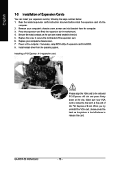
... card is locked by following the steps outlined below: 1. Press the expansion card firmly into the computer. 2. Power on the card are indeed seated in motherboard. 4. Install related driver from the computer. 3. When you try uninstall the VGA card, please press the latch as the picture to the left shows to.... Installing a PCI Express x16 expansion card: Please align the VGA card to the onboard PCI Express x16 slot and press firmly down on the slot. GA-M61P-S3 Motherboard - 16 -
... card is locked by following the steps outlined below: 1. Press the expansion card firmly into the computer. 2. Power on the card are indeed seated in motherboard. 4. Install related driver from the computer. 3. When you try uninstall the VGA card, please press the latch as the picture to the left shows to.... Installing a PCI Express x16 expansion card: Please align the VGA card to the onboard PCI Express x16 slot and press firmly down on the slot. GA-M61P-S3 Motherboard - 16 -

Manual
Page 18
... for detailed software configuration information. 1-7 Connectors Introduction 1 3 10 18 17 11 12 16 15 1) ATX_12V 2) ATX (Power Connector) 3) CPU_FAN 4) SYS_FAN 5) IDE 6) FDD 7) SATAII0 / 1 / 2 / 3 8) PWR_LED 9) F_PANEL GA-M61P-S3 Motherboard 2 5 7 13 9 6 14 8 4 10) F_AUDIO 11) CD_IN 12) SPDIF_IO 13) F_USB1 / F_USB2 / F_USB3 14) F1_1394 / F2_1394 15) COMB 16) CI 17) CLR_CMOS 18) BATTERY - 18 - Microphone...
... for detailed software configuration information. 1-7 Connectors Introduction 1 3 10 18 17 11 12 16 15 1) ATX_12V 2) ATX (Power Connector) 3) CPU_FAN 4) SYS_FAN 5) IDE 6) FDD 7) SATAII0 / 1 / 2 / 3 8) PWR_LED 9) F_PANEL GA-M61P-S3 Motherboard 2 5 7 13 9 6 14 8 4 10) F_AUDIO 11) CD_IN 12) SPDIF_IO 13) F_USB1 / F_USB2 / F_USB3 14) F1_1394 / F2_1394 15) COMB 16) CI 17) CLR_CMOS 18) BATTERY - 18 - Microphone...

Manual
Page 19
... power connector mainly supplies power to handle the system voltage requirements. If you use a power supply that all the components on the motherboard. Hardware Installation If the ATX_12V power connector is able to the CPU. Align the power connector with its proper location on the... motherboard before plugging in the power cord ; otherwise, please do not remove it. 3 4 1 2 ATX_12V Pin No. 1 2 3 4 Definition GND GND +12V +12V 12 24 1...
... power connector mainly supplies power to handle the system voltage requirements. If you use a power supply that all the components on the motherboard. Hardware Installation If the ATX_12V power connector is able to the CPU. Align the power connector with its proper location on the... motherboard before plugging in the power cord ; otherwise, please do not remove it. 3 4 1 2 ATX_12V Pin No. 1 2 3 4 Definition GND GND +12V +12V 12 24 1...

Manual
Page 20
... the instructions located on the IDE device). Before attaching the IDE cable, please take note of the foolproof groove in the IDE connector. 40 39 GA-M61P-S3 Motherboard 2 1 - 20 - The black connector wire is the ground wire (GND).
... the instructions located on the IDE device). Before attaching the IDE cable, please take note of the foolproof groove in the IDE connector. 40 39 GA-M61P-S3 Motherboard 2 1 - 20 - The black connector wire is the ground wire (GND).

Manual
Page 22
... Disk Active LED) (Blue) SPEAK (Speaker Connector) (Amber) RES (Reset Switch) (Green) PW (Power Switch) (Red) MSG (Message LED/Power/Sleep LED) (Yellow) NC ( Purple) GA-M61P-S3 Motherboard Reset Switch IDE Hard Disk Active LED Pin 1: LED anode(+) Pin 2: LED cathode(-) Pin 1: Power Pin 2- Pin 3: NC Pin 4: Data(-) Open: Normal Close: Reset Hardware...
... Disk Active LED) (Blue) SPEAK (Speaker Connector) (Amber) RES (Reset Switch) (Green) PW (Power Switch) (Red) MSG (Message LED/Power/Sleep LED) (Yellow) NC ( Purple) GA-M61P-S3 Motherboard Reset Switch IDE Hard Disk Active LED Pin 1: LED anode(+) Pin 2: LED cathode(-) Pin 1: Power Pin 2- Pin 3: NC Pin 4: Data(-) Open: Normal Close: Reset Hardware...

Manual
Page 24
Use S/PDIF IN feature only when your local dealer. 1 2 5 6 Pin No. 1 2 3 4 5 6 Definition Power No Pin SPDIF SPDIFI GND GND GA-M61P-S3 Motherboard - 24 - For optional S/PDIF cable, please contact your device has digital output function. Check the pin assignment carefully while you connect the S/PDIF cable, incorrect ...
Use S/PDIF IN feature only when your local dealer. 1 2 5 6 Pin No. 1 2 3 4 5 6 Definition Power No Pin SPDIF SPDIFI GND GND GA-M61P-S3 Motherboard - 24 - For optional S/PDIF cable, please contact your device has digital output function. Check the pin assignment carefully while you connect the S/PDIF cable, incorrect ...

Manual
Page 26
... allows your nearest dealer for optional COMB cable. You can check the "Case Opened" status in BIOS Setup. 1 Pin No. Pin No. Definition 1 Signal 2 GND GA-M61P-S3 Motherboard - 26 - Check the pin assignments while you connect the COMB cable. English 15) COMB (COMB Connector) Be careful with the polarity of the COMB connector.
... allows your nearest dealer for optional COMB cable. You can check the "Case Opened" status in BIOS Setup. 1 Pin No. Pin No. Definition 1 Signal 2 GND GA-M61P-S3 Motherboard - 26 - Check the pin assignments while you connect the COMB cable. English 15) COMB (COMB Connector) Be careful with the polarity of the COMB connector.

Manual
Page 29
... Page Setup Menu Item Help Restore the previous CMOS value from CMOS, only for Main Menu Main Menu The on the motherboard supplies the necessary power to a new BIOS, either Gigabyte's Q-Flash or @BIOS utility can enter the BIOS setup screen by pressing "Ctrl + F1". BIOS Setup If you to DOS...Setup Menu Load the fail-safe default CMOS value from the Internet. When the power is turned off, the battery on -line description of the motherboard. Quit and not save changes into CMOS Status Page Setup Menu and Option Page Setup Menu - The CMOS SETUP saves the configuration in system ...
... Page Setup Menu Item Help Restore the previous CMOS value from CMOS, only for Main Menu Main Menu The on the motherboard supplies the necessary power to a new BIOS, either Gigabyte's Q-Flash or @BIOS utility can enter the BIOS setup screen by pressing "Ctrl + F1". BIOS Setup If you to DOS...Setup Menu Load the fail-safe default CMOS value from the Internet. When the power is turned off, the battery on -line description of the motherboard. Quit and not save changes into CMOS Status Page Setup Menu and Option Page Setup Menu - The CMOS SETUP saves the configuration in system ...

Manual
Page 30
... Setup when somehow the system is not stable as figure below) will appear on cards) device. Select the Load Optimized Defaults item in this menu. M61P-S3 D8 . . . . :BIOS Setup/Q-Flash, : Xpress Recovery2, : Boot Menu 11/23/2006-NV-MCP61-6A61KG04C-00 : Boot Menu Use < > or < > to select a ...settings for onboard (or add-on the screen. Press to accept . This action makes the system reset to accept or enter the sub-menu. GA-M61P-S3 Motherboard - 30 - If you don't find the settings you enter Award BIOS CMOS Setup Utility, the Main Menu (as usual. Use arrow keys to...
... Setup when somehow the system is not stable as figure below) will appear on cards) device. Select the Load Optimized Defaults item in this menu. M61P-S3 D8 . . . . :BIOS Setup/Q-Flash, : Xpress Recovery2, : Boot Menu 11/23/2006-NV-MCP61-6A61KG04C-00 : Boot Menu Use < > or < > to select a ...settings for onboard (or add-on the screen. Press to accept . This action makes the system reset to accept or enter the sub-menu. GA-M61P-S3 Motherboard - 30 - If you don't find the settings you enter Award BIOS CMOS Setup Utility, the Main Menu (as usual. Use arrow keys to...

Manual
Page 32
... 24-hour military-time clock. You can use one of three methods: • Auto Allows BIOS to automatically detect IDE/SATA devices during POST. (default) GA-M61P-S3 Motherboard - 32 - Week The week, from Sun to 31 (or the maximum allowed in the month) Year The year, from 1 to Sat, determined by the BIOS...
... 24-hour military-time clock. You can use one of three methods: • Auto Allows BIOS to automatically detect IDE/SATA devices during POST. (default) GA-M61P-S3 Motherboard - 32 - Week The week, from Sun to 31 (or the maximum allowed in the month) Year The year, from 1 to Sat, determined by the BIOS...


