Manual
Page 1
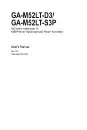
GA-M52LT-D3/ GA-M52LT-S3P AM3 socket motherboard for AMD Phenom™ II processor/AMD Athlon™ II processor User's Manual Rev. 2301 12ME-M52LTD3-2301R
GA-M52LT-D3/ GA-M52LT-S3P AM3 socket motherboard for AMD Phenom™ II processor/AMD Athlon™ II processor User's Manual Rev. 2301 12ME-M52LTD3-2301R

Manual
Page 3
... features in any means without prior notice. No part of the product, read the User's Manual. Check your motherboard looks like this product, GIGABYTE provides the following types of documentations: For quick set-up of this manual may be reproduced, copied, translated, ... written permission. Documentation Classifications In order to assist in this manual are legally registered to use of GIGABYTE. For example, "REV: 1.0" means the revision of the motherboard is the property of this : "REV: X.X." For detailed product information, carefully read the Quick Installation...
... features in any means without prior notice. No part of the product, read the User's Manual. Check your motherboard looks like this product, GIGABYTE provides the following types of documentations: For quick set-up of this manual may be reproduced, copied, translated, ... written permission. Documentation Classifications In order to assist in this manual are legally registered to use of GIGABYTE. For example, "REV: 1.0" means the revision of the motherboard is the property of this : "REV: X.X." For detailed product information, carefully read the Quick Installation...

Manual
Page 4
Table of Contents Box Contents...6 Optional Items...6 GA-M52LT-D3/GA-M52LT-S3P Motherboard Layout 7 GA-M52LT-D3/GA-M52LT-S3P Motherboard Block Diagram 8 Chapter 1 Hardware Installation 9 1-1 Installation Precautions 9 1-2 Product Specifications 10 1-3 Installing the CPU and CPU Cooler 12 1-3-1 Installing the CPU 12 1-3-2 Installing the CPU Cooler ...
Table of Contents Box Contents...6 Optional Items...6 GA-M52LT-D3/GA-M52LT-S3P Motherboard Layout 7 GA-M52LT-D3/GA-M52LT-S3P Motherboard Block Diagram 8 Chapter 1 Hardware Installation 9 1-1 Installation Precautions 9 1-2 Product Specifications 10 1-3 Installing the CPU and CPU Cooler 12 1-3-1 Installing the CPU 12 1-3-2 Installing the CPU Cooler ...
Manual
Page 6
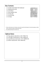
Box Contents GA-M52LT-D3/GA-M52LT-S3P motherboard Motherboard driver disk User's Manual Quick Installation Guide One IDE cable One SATA cable I/O Shield • The box contents above are subject to change without notice. • The motherboard image is for reference only and the actual items shall depend on the product package you obtain. The box contents are...
Box Contents GA-M52LT-D3/GA-M52LT-S3P motherboard Motherboard driver disk User's Manual Quick Installation Guide One IDE cable One SATA cable I/O Shield • The box contents above are subject to change without notice. • The motherboard image is for reference only and the actual items shall depend on the product package you obtain. The box contents are...

Manual
Page 7
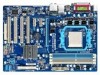
GA-M52LT-D3/GA-M52LT-S3P Motherboard Layout KB_MS ATX_12V Socket AM3 COAXIAL LPT COMA R_USB USB_LAN CPU_FAN AUDIO F_AUDIO GA-M52LT-D3/GA-M52LT-S3P PCIEX16 SPDIF_O Realtek RTL8201EL PCIEX1_1 PCIEX1_2 BAT CODEC PCI1 CLR_CMOS NVIDIA® nForce 520LE CD_IN PCI2 SPDIF_I PCI3 iTE IT8720 PCI4 M_BIOS B_BIOS F_PANEL FDD SYS_FAN F_USB2 F_USB1 DDR3_1 DDR3_2 DDR3_3 DDR3_4 PWR_FAN ATX IDE SATA2_1 SATA2_0 "*" The GA-M52LT-D3 adopts All-Solid Capacitor design. - 7 -
GA-M52LT-D3/GA-M52LT-S3P Motherboard Layout KB_MS ATX_12V Socket AM3 COAXIAL LPT COMA R_USB USB_LAN CPU_FAN AUDIO F_AUDIO GA-M52LT-D3/GA-M52LT-S3P PCIEX16 SPDIF_O Realtek RTL8201EL PCIEX1_1 PCIEX1_2 BAT CODEC PCI1 CLR_CMOS NVIDIA® nForce 520LE CD_IN PCI2 SPDIF_I PCI3 iTE IT8720 PCI4 M_BIOS B_BIOS F_PANEL FDD SYS_FAN F_USB2 F_USB1 DDR3_1 DDR3_2 DDR3_3 DDR3_4 PWR_FAN ATX IDE SATA2_1 SATA2_0 "*" The GA-M52LT-D3 adopts All-Solid Capacitor design. - 7 -

Manual
Page 8
GA-M52LT-D3/GA-M52LT-S3P Motherboard Block Diagram AM3 CPU CPU CLK+/- (200 MHz) DDR3 1666(O.C.)/1333/1066 MHz Dual Channel Memory PCIe CLK (100 MHz) 1 PCI Express x16 Hyper Transport PCI Express Bus x1 x1 PCIe CLK (100 MHz) 2 PCI Express x1 2 SATA 3Gb/s NVIDIA® nForce 520LE Realtek RTL8201EL RJ45 LAN 8 USB 2.0/1.1 ATA-133/100/66/33 IDE Channel PCI Bus CODEC LPC Bus iTE IT8720 Dual BIOS Floppy COM Port LPT Port PS/2 KB/Mouse Surround Speaker Out Center/Subwoofer Speaker Out Side Speaker Out MIC Line Out Line In S/PDIF In S/PDIF Out 4 PCI PCI CLK (33 MHz) - 8 -
GA-M52LT-D3/GA-M52LT-S3P Motherboard Block Diagram AM3 CPU CPU CLK+/- (200 MHz) DDR3 1666(O.C.)/1333/1066 MHz Dual Channel Memory PCIe CLK (100 MHz) 1 PCI Express x16 Hyper Transport PCI Express Bus x1 x1 PCIe CLK (100 MHz) 2 PCI Express x1 2 SATA 3Gb/s NVIDIA® nForce 520LE Realtek RTL8201EL RJ45 LAN 8 USB 2.0/1.1 ATA-133/100/66/33 IDE Channel PCI Bus CODEC LPC Bus iTE IT8720 Dual BIOS Floppy COM Port LPT Port PS/2 KB/Mouse Surround Speaker Out Center/Subwoofer Speaker Out Side Speaker Out MIC Line Out Line In S/PDIF In S/PDIF Out 4 PCI PCI CLK (33 MHz) - 8 -

Manual
Page 9
...dealer. ponents such as a result of electrostatic discharge (ESD). If you are connected tightly and securely. • When handling the motherboard, avoid touching any installation steps or have a problem related to the use of the product, please consult a certified computer technician. -... to wear an electrostatic discharge (ESD) wrist strap when handling electronic com- Chapter 1 Hardware Installation 1-1 Installation Precautions The motherboard contains numerous delicate electronic circuits and components which can lead to damage to system components as well as physical harm to the...
...dealer. ponents such as a result of electrostatic discharge (ESD). If you are connected tightly and securely. • When handling the motherboard, avoid touching any installation steps or have a problem related to the use of the product, please consult a certified computer technician. -... to wear an electrostatic discharge (ESD) wrist strap when handling electronic com- Chapter 1 Hardware Installation 1-1 Installation Precautions The motherboard contains numerous delicate electronic circuits and components which can lead to damage to system components as well as physical harm to the...

Manual
Page 11
... CPU/system fan speed control function is supported will depend on the CPU/system cooler you install. (Note 3) Available functions in EasyTune may differ by motherboard model. - 11 -
... CPU/system fan speed control function is supported will depend on the CPU/system cooler you install. (Note 3) Available functions in EasyTune may differ by motherboard model. - 11 -

Manual
Page 12
... grease on the surface of the CPU. • Do not turn on the computer if the CPU cooler is not recommended that the motherboard supports the CPU. (Go to GIGABYTE's website for the latest CPU support list.) • Always turn off the computer and unplug the power cord from the power outlet...
... grease on the surface of the CPU. • Do not turn on the computer if the CPU cooler is not recommended that the motherboard supports the CPU. (Go to GIGABYTE's website for the latest CPU support list.) • Always turn off the computer and unplug the power cord from the power outlet...

Manual
Page 13
... the CPU socket and gently insert the CPU into the fully locked position. - 13 - Follow the steps below to correctly install the CPU into the motherboard CPU socket. • Before installing the CPU, make sure to turn off the computer and unplug the power cord from the power outlet to prevent...
... the CPU socket and gently insert the CPU into the fully locked position. - 13 - Follow the steps below to correctly install the CPU into the motherboard CPU socket. • Before installing the CPU, make sure to turn off the computer and unplug the power cord from the power outlet to prevent...

Manual
Page 14
... the retention frame. 1-3-2 Installing the CPU Cooler Follow the steps below to correctly install the CPU cooler on the CPU. (The following procedure uses the GIGABYTE cooler as the picture above shows) to lock into place. (Refer to your CPU cooler installation manual for instructions on installing the cooler.) Step 5: Finally...
... the retention frame. 1-3-2 Installing the CPU Cooler Follow the steps below to correctly install the CPU cooler on the CPU. (The following procedure uses the GIGABYTE cooler as the picture above shows) to lock into place. (Refer to your CPU cooler installation manual for instructions on installing the cooler.) Step 5: Finally...

Manual
Page 15
... - - - - - - The four DDR3 memory sockets are unable to insert the memory, switch the direction. 1-4-1 Dual Channel Memory Configuration This motherboard provides four DDR3 memory sockets and supports Dual Channel Technology. When enabling Dual Channel mode with two or four memory modules, it is recommended that...begin to install the memory: • Make sure that memory of the same capacity, brand, speed, and chips be used . (Go to GIGABYTE's website for optimum performance. - 15 - A memory module can be enabled if only one direction. After the memory is installed. 2. Hardware...
... - - - - - - The four DDR3 memory sockets are unable to insert the memory, switch the direction. 1-4-1 Dual Channel Memory Configuration This motherboard provides four DDR3 memory sockets and supports Dual Channel Technology. When enabling Dual Channel mode with two or four memory modules, it is recommended that...begin to install the memory: • Make sure that memory of the same capacity, brand, speed, and chips be used . (Go to GIGABYTE's website for optimum performance. - 15 - A memory module can be enabled if only one direction. After the memory is installed. 2. Hardware...

Manual
Page 16
.... Hardware Installation - 16 - DDR3 and DDR2 DIMMs are not compatible to each other or DDR DIMMs. Be sure to correctly install your fingers on this motherboard. Spread the retaining clips at both ends of the socket will snap into the memory socket. Step 2: The clips at both ends of the memory...
.... Hardware Installation - 16 - DDR3 and DDR2 DIMMs are not compatible to each other or DDR DIMMs. Be sure to correctly install your fingers on this motherboard. Spread the retaining clips at both ends of the socket will snap into the memory socket. Step 2: The clips at both ends of the memory...

Manual
Page 17
... install your expansion card(s). 7. Remove the metal slot cover from the power outlet before you begin to install an expansion card: • Make sure the motherboard supports the expansion card. After installing all expansion cards, replace the chassis cover(s). 6. If necessary, go to BIOS Setup to make any required BIOS changes...
... install your expansion card(s). 7. Remove the metal slot cover from the power outlet before you begin to install an expansion card: • Make sure the motherboard supports the expansion card. After installing all expansion cards, replace the chassis cover(s). 6. If necessary, go to BIOS Setup to make any required BIOS changes...

Manual
Page 18
... an optical drive, walkman, etc. • When removing the cable connected to an external audio system that your device and then remove it from the motherboard. • When removing the cable, pull it side to side to connect a PS/2 keyboard. Connection LED Activity LED LAN Port Connection LED: State Description On...
... an optical drive, walkman, etc. • When removing the cable connected to an external audio system that your device and then remove it from the motherboard. • When removing the cable, pull it side to side to connect a PS/2 keyboard. Connection LED Activity LED LAN Port Connection LED: State Description On...

Manual
Page 20
..., make sure your devices are compliant with the connectors you wish to connect. • Before installing the devices, be sure to the connector on the motherboard.
..., make sure your devices are compliant with the connectors you wish to connect. • Before installing the devices, be sure to the connector on the motherboard.

Manual
Page 21
... the power supply is not connected, the computer will not start. If the 12V power connector is turned off and all the components on the motherboard. 1/2) ATX_12V/ATX (2x2 12V Power Connector and 2x12 Main Power Connector) With the use of the power connector, the power supply can lead to an...
... the power supply is not connected, the computer will not start. If the 12V power connector is turned off and all the components on the motherboard. 1/2) ATX_12V/ATX (2x2 12V Power Connector and 2x12 Main Power Connector) With the use of the power connector, the power supply can lead to an...

Manual
Page 22
The types of floppy disk drives supported are not configuration jumper blocks. The pin 1 of different color. The motherboard supports CPU fan speed control, which requires the use of the connector and the floppy disk drive cable. For optimum...). For purchasing the optional floppy disk drive cable, please contact the local dealer. 33 1 34 2 Hardware Installation - 22 - 3/4/5) CPU_FAN/SYS_FAN/PWR_FAN (Fan Headers) The motherboard has a 4-pin CPU fan header (CPU_FAN), a 3-pin system fan header (SYS_FAN), and a 3-pin power fan header (PWR_FAN). Definition 1 GND 2 +12V 3 Sense...
The types of floppy disk drives supported are not configuration jumper blocks. The pin 1 of different color. The motherboard supports CPU fan speed control, which requires the use of the connector and the floppy disk drive cable. For optimum...). For purchasing the optional floppy disk drive cable, please contact the local dealer. 33 1 34 2 Hardware Installation - 22 - 3/4/5) CPU_FAN/SYS_FAN/PWR_FAN (Fan Headers) The motherboard has a 4-pin CPU fan header (CPU_FAN), a 3-pin system fan header (SYS_FAN), and a 3-pin power fan header (PWR_FAN). Definition 1 GND 2 +12V 3 Sense...

Manual
Page 25
.... 11) CD_IN (CD In Connector) You may connect your optical drive to this header. Incorrect connection between the module connector and the motherboard header will be present on how to activate AC'97 functionality via the audio software in Chapter 5, "Configuring 2/4/5.1/7.1-Channel Audio." • ...Audio signals will make the device unable to the instructions on both of the motherboard header. If your chassis provides an AC'97 front panel audio module, refer to work or even damage it. 10) F_AUDIO (Front ...
.... 11) CD_IN (CD In Connector) You may connect your optical drive to this header. Incorrect connection between the module connector and the motherboard header will be present on how to activate AC'97 functionality via the audio software in Chapter 5, "Configuring 2/4/5.1/7.1-Channel Audio." • ...Audio signals will make the device unable to the instructions on both of the motherboard header. If your chassis provides an AC'97 front panel audio module, refer to work or even damage it. 10) F_AUDIO (Front ...

Manual
Page 26
... an optional S/PDIF In cable. For information about connecting the S/PDIF digital audio cable, carefully read the manual for digital audio output from your motherboard to your motherboard to use a S/PDIF digital audio cable for your expansion card. 1 Pin No. 12) SPDIF_I (S/PDIF In Header) This header supports digital S/PDIF In and...
... an optional S/PDIF In cable. For information about connecting the S/PDIF digital audio cable, carefully read the manual for digital audio output from your motherboard to your motherboard to use a S/PDIF digital audio cable for your expansion card. 1 Pin No. 12) SPDIF_I (S/PDIF In Header) This header supports digital S/PDIF In and...


