Manual
Page 1
GA-M52L-S3 AM2 socket motherboard for AMD AthlonTM 64 FX processor/ AMD AthlonTM 64 X2 Dual-Core processor/ AMD AthlonTM 64 processor/AMD SempronTM processor User's Manual Rev. 2001 12ME-M52LS3-2001R
GA-M52L-S3 AM2 socket motherboard for AMD AthlonTM 64 FX processor/ AMD AthlonTM 64 X2 Dual-Core processor/ AMD AthlonTM 64 processor/AMD SempronTM processor User's Manual Rev. 2001 12ME-M52LS3-2001R

Manual
Page 3
... by GIGA-BYTE TECHNOLOGY CO., LTD as the exclu- Copyright © 2008 GIGA-BYTE TECHNOLOGY CO., LTD. Changes to GIGABYTE UNITED INC. For example, "REV: 1.0" means the revision of GIGABYTE branded motherboards. GIGABYTE UNITED INC. by GIGABYTE without GIGABYTE's prior written permission. is exclusively licensed to the specifications and features in any means without prior notice.
... by GIGA-BYTE TECHNOLOGY CO., LTD as the exclu- Copyright © 2008 GIGA-BYTE TECHNOLOGY CO., LTD. Changes to GIGABYTE UNITED INC. For example, "REV: 1.0" means the revision of GIGABYTE branded motherboards. GIGABYTE UNITED INC. by GIGABYTE without GIGABYTE's prior written permission. is exclusively licensed to the specifications and features in any means without prior notice.

Manual
Page 4
Table of Contents Box Contents ...6 OptionalItems ...6 GA-M52L-S3 Motherboard Layout 7 Block Diagram ...8 Chapter 1 Hardware Installation 9 1-1 Installation Precautions 9 1-2 Product Specifications 10 1-3 Installing the CPU and CPU Cooler 12 1-3-1 Installing the CPU 12 1-3-2 Installing the CPU ...
Table of Contents Box Contents ...6 OptionalItems ...6 GA-M52L-S3 Motherboard Layout 7 Block Diagram ...8 Chapter 1 Hardware Installation 9 1-1 Installation Precautions 9 1-2 Product Specifications 10 1-3 Installing the CPU and CPU Cooler 12 1-3-1 Installing the CPU 12 1-3-2 Installing the CPU ...
Manual
Page 6
... No. 12CR1-1UB030-51R) 2-port SATA power cable (Part No. 12CF1-2SERPW-01R) S/PDIF in cable (Part No. 12CR1-1SPDIN-01R) - 6 - Box Contents GA-M52L-S3 motherboard Motherboard driver disk Motherboard driver disk (For Windows Vista) User's Manual Quick Installation Guide One IDE cable and one floppy disk drive cable One SATA 3Gb/s cable I/O Shield... • The box contents above are subject to change without notice. • The motherboard image is for reference only and the actual items shall depend on product package you obtain.
... No. 12CR1-1UB030-51R) 2-port SATA power cable (Part No. 12CF1-2SERPW-01R) S/PDIF in cable (Part No. 12CR1-1SPDIN-01R) - 6 - Box Contents GA-M52L-S3 motherboard Motherboard driver disk Motherboard driver disk (For Windows Vista) User's Manual Quick Installation Guide One IDE cable and one floppy disk drive cable One SATA 3Gb/s cable I/O Shield... • The box contents above are subject to change without notice. • The motherboard image is for reference only and the actual items shall depend on product package you obtain.

Manual
Page 7
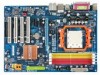
GA-M52L-S3 Motherboard Layout KB_MS COAXIAL Socket AM2 ATX COMA LPT USB R_USB LAN ATX_12V CPU_FAN AUDIO F_AUDIO PCIE_16 GA-M52L-S3 DDRII_1 DDRII_2 DDRII_3 DDRII_4 SPDIF_O Realtek PCIE_1 8201CL BIOS BATTERY PCIE_2 CODEC CLR_CMOS NVIDIA® PCI1 nForce 520LE (Geforce 6100/ nForce 430) CD_IN SPDIF_I PCI2 IDE IT8716 CI PCI3 PCI4 FDD F_USB2 F_USB1 SYS_FAN F_PANEL PWR_LED SATAII1 SATAII0 - 7 -
GA-M52L-S3 Motherboard Layout KB_MS COAXIAL Socket AM2 ATX COMA LPT USB R_USB LAN ATX_12V CPU_FAN AUDIO F_AUDIO PCIE_16 GA-M52L-S3 DDRII_1 DDRII_2 DDRII_3 DDRII_4 SPDIF_O Realtek PCIE_1 8201CL BIOS BATTERY PCIE_2 CODEC CLR_CMOS NVIDIA® PCI1 nForce 520LE (Geforce 6100/ nForce 430) CD_IN SPDIF_I PCI2 IDE IT8716 CI PCI3 PCI4 FDD F_USB2 F_USB1 SYS_FAN F_PANEL PWR_LED SATAII1 SATAII0 - 7 -

Manual
Page 9
...that all cables and power connectors of your hardware components are connected. • To prevent damage to the motherboard, do not allow screws to come in contact with the motherboard circuit or its components. • Make sure there are no leftover screws or metal components placed on the... has been turned off. • Before turning on the power, make sure they are connected tightly and securely. • When handling the motherboard, avoid touching any metal leads or connectors. • It is best to wear an electrostatic discharge (ESD) wrist strap when handling electronic components...
...that all cables and power connectors of your hardware components are connected. • To prevent damage to the motherboard, do not allow screws to come in contact with the motherboard circuit or its components. • Make sure there are no leftover screws or metal components placed on the... has been turned off. • Before turning on the power, make sure they are connected tightly and securely. • When handling the motherboard, avoid touching any metal leads or connectors. • It is best to wear an electrostatic discharge (ESD) wrist strap when handling electronic components...

Manual
Page 10
...GB of system memory (Note 1) Dual channel memory architecture Support for DDR2 800/667/533/400 MHz memory modules (Go to GIGABYTE's website for the latest memory support list.) Realtek ALC883 codec High Definition Audio 2/4/5.1/7.1-channel Support for S/PDIF In/Out Support ...panel audio header 1 x CD In connector 1 x S/PDIF In header 1 x S/PDIF Out header 2 x USB 2.0/1.1 headers 1 x chassis intrusion header 1 x power LED header GA-M52L-S3 Motherboard - 10 - Support for CD In RTL 8201CL chip (10/100 Mbit) 1 x PCI Express x16 slot 2 x PCI Express x1 slots 4 x PCI slots NVIDIA® nForce 520LE...
...GB of system memory (Note 1) Dual channel memory architecture Support for DDR2 800/667/533/400 MHz memory modules (Go to GIGABYTE's website for the latest memory support list.) Realtek ALC883 codec High Definition Audio 2/4/5.1/7.1-channel Support for S/PDIF In/Out Support ...panel audio header 1 x CD In connector 1 x S/PDIF In header 1 x S/PDIF Out header 2 x USB 2.0/1.1 headers 1 x chassis intrusion header 1 x power LED header GA-M52L-S3 Motherboard - 10 - Support for CD In RTL 8201CL chip (10/100 Mbit) 1 x PCI Express x16 slot 2 x PCI Express x1 slots 4 x PCI slots NVIDIA® nForce 520LE...

Manual
Page 11
.... (Note 2) Whether the CPU fan speed control function is supported will depend on the CPU you install. (Note 3) Available functions in EasyTune may differ by motherboard model. - 11 - Hardware Installation
.... (Note 2) Whether the CPU fan speed control function is supported will depend on the CPU you install. (Note 3) Available functions in EasyTune may differ by motherboard model. - 11 - Hardware Installation

Manual
Page 12
mended that the motherboard supports the CPU. (Go to GIGABYTE's website for the peripherals. English 1-3 Installing the CPU and CPU Cooler Read the following guidelines before installing the CPU to prevent hardware damage. • Locate ... the CPU. It is not installed, otherwise overheating and damage of the Socket AM2 CPU Socket A Small Triangle Marking Denotes CPU Pin One AM2 CPU GA-M52L-S3 Motherboard - 12 - If you begin to install the CPU: • Make sure that the system bus frequency be inserted if oriented incorrectly. • Apply an even...
mended that the motherboard supports the CPU. (Go to GIGABYTE's website for the peripherals. English 1-3 Installing the CPU and CPU Cooler Read the following guidelines before installing the CPU to prevent hardware damage. • Locate ... the CPU. It is not installed, otherwise overheating and damage of the Socket AM2 CPU Socket A Small Triangle Marking Denotes CPU Pin One AM2 CPU GA-M52L-S3 Motherboard - 12 - If you begin to install the CPU: • Make sure that the system bus frequency be inserted if oriented incorrectly. • Apply an even...

Manual
Page 13
... socket. Hardware Installation Adjust the CPU orientation if this occurs. - 13 - Follow the steps below to the CPU. Do not force the CPU into the motherboard CPU socket. The CPU cannot fit in if oriented incorrectly. Before installing the CPU, make sure to turn off the computer and unplug the power...
... socket. Hardware Installation Adjust the CPU orientation if this occurs. - 13 - Follow the steps below to the CPU. Do not force the CPU into the motherboard CPU socket. The CPU cannot fit in if oriented incorrectly. Before installing the CPU, make sure to turn off the computer and unplug the power...

Manual
Page 14
... 1: Apply an even and thin layer of thermal grease on the retention frame. GA-M52L-S3 Motherboard - 14 - English 1-3-2 Installing the CPU Cooler Follow the steps below to correctly install the CPU cooler on the CPU. (The following procedure uses the GIGABYTE cooler as the picture above shows) to lock into place. (Refer to your...
... 1: Apply an even and thin layer of thermal grease on the retention frame. GA-M52L-S3 Motherboard - 14 - English 1-3-2 Installing the CPU Cooler Follow the steps below to correctly install the CPU cooler on the CPU. (The following procedure uses the GIGABYTE cooler as the picture above shows) to lock into place. (Refer to your...

Manual
Page 15
...sockets are unable to prevent hardware damage. • Memory modules have a foolproof design. After the memory is recommended that the motherboard supports the memory. English 1-4 Installing the Memory Read the following : Channel 0: DDRII_1, DDRII_3 Channel 1: DDRII_2, DDRII_4 Dual... memory, switch the direction. 1-4-1 Dual Channel Memory Configuration This motherboard provides four DDR2 memory sockets and supports Dual Channel Technology. Hardware Installation Dual Channel mode cannot be used . (Go to GIGABYTE's website for optimum performance. - 15 - It is installed....
...sockets are unable to prevent hardware damage. • Memory modules have a foolproof design. After the memory is recommended that the motherboard supports the memory. English 1-4 Installing the Memory Read the following : Channel 0: DDRII_1, DDRII_3 Channel 1: DDRII_2, DDRII_4 Dual... memory, switch the direction. 1-4-1 Dual Channel Memory Configuration This motherboard provides four DDR2 memory sockets and supports Dual Channel Technology. Hardware Installation Dual Channel mode cannot be used . (Go to GIGABYTE's website for optimum performance. - 15 - It is installed....

Manual
Page 16
... of the socket will snap into the memory socket. GA-M52L-S3 Motherboard - 16 - English 1-4-2 Installing a Memory Before installing a memory module , make sure to turn off the computer and unplug the power cord from the power outlet to prevent damage to install DDR2 DIMMs on this motherboard. Step 1: Note the orientation of the memory, push...
... of the socket will snap into the memory socket. GA-M52L-S3 Motherboard - 16 - English 1-4-2 Installing a Memory Before installing a memory module , make sure to turn off the computer and unplug the power cord from the power outlet to prevent damage to install DDR2 DIMMs on this motherboard. Step 1: Note the orientation of the memory, push...

Manual
Page 17
...; Removing the Card: Press the white latch at the end of the PCI Express x16 slot to install an expansion card: • Make sure the motherboard supports the expansion card. Example: Installing and Removing a PCI Express x16 Graphics Card: • Installing a Graphics Card: Gently insert the graphics card into the slot...
...; Removing the Card: Press the white latch at the end of the PCI Express x16 slot to install an expansion card: • Make sure the motherboard supports the expansion card. Example: Installing and Removing a PCI Express x16 Graphics Card: • Installing a Graphics Card: Gently insert the graphics card into the slot...

Manual
Page 18
...The Fast Ethernet LAN port provides Internet connection at up to an external audio system that your device and then remove it from the motherboard. • When removing the cable, pull it side to side to connect devices such as a mouse, modem or other peripherals. ... data rate Activity LED: State Description Blinking Data transmission or receiving is occurring Off No data transmission or receiving is also called a printer port. GA-M52L-S3 Motherboard - 18 - English 1-6 Back Panel Connectors PS/2 Keyboard and PS/2 Mouse Port Use the upper port (green) to connect a PS/2 mouse...
...The Fast Ethernet LAN port provides Internet connection at up to an external audio system that your device and then remove it from the motherboard. • When removing the cable, pull it side to side to connect devices such as a mouse, modem or other peripherals. ... data rate Activity LED: State Description Blinking Data transmission or receiving is occurring Off No data transmission or receiving is also called a printer port. GA-M52L-S3 Motherboard - 18 - English 1-6 Back Panel Connectors PS/2 Keyboard and PS/2 Mouse Port Use the upper port (green) to connect a PS/2 mouse...

Manual
Page 20
GA-M52L-S3 Motherboard - 20 - Unplug the power cord from the power outlet to prevent damage to the devices. • After installing the device and before connecting external devices: &#... devices and your devices are compliant with the connectors you wish to connect. • Before installing the devices, be sure to the connector on the motherboard. English 1-7 Internal Connectors 1 3 11 14 9 17 12 13 16 1) ATX_12V 2) ATX 3) CPU_FAN 4) SYS_FAN 5) FDD 6) IDE 7) SATAII0 / 1 8) PWR_LED 9) BATTERY 2 6 7 15 10 5 84 10) F_PANEL 11) F_AUDIO...
GA-M52L-S3 Motherboard - 20 - Unplug the power cord from the power outlet to prevent damage to the devices. • After installing the device and before connecting external devices: &#... devices and your devices are compliant with the connectors you wish to connect. • Before installing the devices, be sure to the connector on the motherboard. English 1-7 Internal Connectors 1 3 11 14 9 17 12 13 16 1) ATX_12V 2) ATX 3) CPU_FAN 4) SYS_FAN 5) FDD 6) IDE 7) SATAII0 / 1 8) PWR_LED 9) BATTERY 2 6 7 15 10 5 84 10) F_PANEL 11) F_AUDIO...

Manual
Page 21
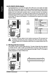
...400W or greater). Before connecting the power connector, first make sure the power supply is turned off and all the components on the motherboard. Connect the power supply cable to the CPU. If a power supply is compatible with power supplies with 2x10 power connectors. When ...into pins under the protective cover when using a 2x12 power supply, remove the protective cover from the main power connector on the motherboard. The 12V power connector mainly supplies power to the power connector in the correct orientation. Hardware Installation The power connector possesses a ...
...400W or greater). Before connecting the power connector, first make sure the power supply is turned off and all the components on the motherboard. Connect the power supply cable to the CPU. If a power supply is compatible with power supplies with 2x10 power connectors. When ...into pins under the protective cover when using a 2x12 power supply, remove the protective cover from the main power connector on the motherboard. The 12V power connector mainly supplies power to the power connector in the correct orientation. Hardware Installation The power connector possesses a ...
Manual
Page 22
..., 1.44 MB, and 2.88 MB. CPU_FAN: Pin No. The types of different color. 33 1 34 2 GA-M52L-S3 Motherboard - 22 - English 3/4) CPU_FAN/SYS_FAN (Fan Headers) The motherboard has a 4-pin CPU fan header (CPU_FAN) and a 3-pin system fan header (SYS_FAN). The motherboard supports CPU fan speed control, which requires the use of the connector and the floppy...
..., 1.44 MB, and 2.88 MB. CPU_FAN: Pin No. The types of different color. 33 1 34 2 GA-M52L-S3 Motherboard - 22 - English 3/4) CPU_FAN/SYS_FAN (Fan Headers) The motherboard has a 4-pin CPU fan header (CPU_FAN) and a 3-pin system fan header (SYS_FAN). The motherboard supports CPU fan speed control, which requires the use of the connector and the floppy...
Manual
Page 24
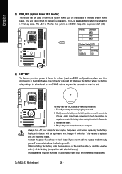
...restart your computer. • Always turn off . Pin No. 1 2 3 Definition MPD+ MPDMPD- 1 System Status LED S0 On S1 Blinking S3/S4/S5 Off 9) BATTERY The battery provides power to keep the values (such as BIOS configurations, date, and time information) in accordance with an...power cord before replacing the battery. • Replace the battery with local environmental regulations. The LED is off when the system is operating. GA-M52L-S3 Motherboard - 24 - English 8) PWR_LED (System Power LED Header) This header can be lost. You may be used to a low level, or...
...restart your computer. • Always turn off . Pin No. 1 2 3 Definition MPD+ MPDMPD- 1 System Status LED S0 On S1 Blinking S3/S4/S5 Off 9) BATTERY The battery provides power to keep the values (such as BIOS configurations, date, and time information) in accordance with an...power cord before replacing the battery. • Replace the battery with local environmental regulations. The LED is off when the system is operating. GA-M52L-S3 Motherboard - 24 - English 8) PWR_LED (System Power LED Header) This header can be lost. You may be used to a low level, or...

Manual
Page 26
...(CD In Connector, Black) You may connect your optical drive to this header. Definition 1 CD-L 1 2 GND 3 GND 4 CD-R GA-M52L-S3 Motherboard - 26 - For HD Front Panel Audio: For AC'97 Front Panel Audio: 10 9 Pin No. Pin No. Incorrect connection between the... your chassis front panel audio module to the header. You may connect the audio cable that has separated connectors on each wire instead of the motherboard header. Definition 1 MIC2_L 1 MIC 2 1 2 GND 3 MIC2_R 2 GND 3 MIC Power 4 -ACZ_DET 4 NC 5 LINE2_R 5 Line Out (R) 6 FSENSE1 6 NC 7 ...
...(CD In Connector, Black) You may connect your optical drive to this header. Definition 1 CD-L 1 2 GND 3 GND 4 CD-R GA-M52L-S3 Motherboard - 26 - For HD Front Panel Audio: For AC'97 Front Panel Audio: 10 9 Pin No. Pin No. Incorrect connection between the... your chassis front panel audio module to the header. You may connect the audio cable that has separated connectors on each wire instead of the motherboard header. Definition 1 MIC2_L 1 MIC 2 1 2 GND 3 MIC2_R 2 GND 3 MIC Power 4 -ACZ_DET 4 NC 5 LINE2_R 5 Line Out (R) 6 FSENSE1 6 NC 7 ...


