Manual
Page 10
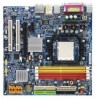
...LAN Š Onboard Marvell 88E1116 PHY(10/100/1000Mbit) Audio Š ALC883 CODEC Š Supports 2 / 4 / 6 / 8 channel audio Š Supports High Definition Audio Š Supports Line In ; Side Speaker Out connection Š SPDIF In/Out connection Š CD In ...support, allowing connection of 4 IDE devices - 4 SATA 3Gb/s connectors (SATAII0_1,SATAII2_3), allowing connection of 4 SATA 3Gb/s devices - Line Out (Front Speaker Out) ; Surround Speaker Out (Rear Speaker Out) ; English 1-2 Feature Summary CPU Š Socket AM2 for additional 2 port by cable GA-M51GM-S2G...
...LAN Š Onboard Marvell 88E1116 PHY(10/100/1000Mbit) Audio Š ALC883 CODEC Š Supports 2 / 4 / 6 / 8 channel audio Š Supports High Definition Audio Š Supports Line In ; Side Speaker Out connection Š SPDIF In/Out connection Š CD In ...support, allowing connection of 4 IDE devices - 4 SATA 3Gb/s connectors (SATAII0_1,SATAII2_3), allowing connection of 4 SATA 3Gb/s devices - Line Out (Front Speaker Out) ; Surround Speaker Out (Rear Speaker Out) ; English 1-2 Feature Summary CPU Š Socket AM2 for additional 2 port by cable GA-M51GM-S2G...
Manual
Page 11
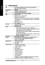
...(Note 2) BIOS Š 1 4Mbit flash ROM Š Use of licensed AWARD BIOS Additional Features Š Supports @BIOS Š Supports Download Center Š Supports Q-Flash Š Supports EasyTune (only supports Hardware Monitor function)(Note 3) Š Supports Xpress Install Š Supports Xpress Recovery2 Š Supports Xpress BIOS Rescue Bundle Software Š Norton Internet Security (OEM version) Form Factor Š Micro...
...(Note 2) BIOS Š 1 4Mbit flash ROM Š Use of licensed AWARD BIOS Additional Features Š Supports @BIOS Š Supports Download Center Š Supports Q-Flash Š Supports EasyTune (only supports Hardware Monitor function)(Note 3) Š Supports Xpress Install Š Supports Xpress Recovery2 Š Supports Xpress BIOS Rescue Bundle Software Š Norton Internet Security (OEM version) Form Factor Š Micro...
Manual
Page 12
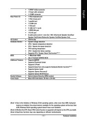
...with the following conditions: 1. The pin 1 location is installed on the CPU by a small triangle that corresponds to see that the motherboard supports the CPU. 2. Gently place the CPU into position making sure that the system bus frequency be set beyond the proper specifications, please do ...fitperfectly into place. Pin One Please use , otherwise overheating and permanent damage of the CPU may occur. 5. The CPU will not insert properly. GA-M51GM-S2G Motherboard - 12 - Please add an even layer of heat paste between the CPU and CPU cooler. 4. Align the CPU to the socket and...
...with the following conditions: 1. The pin 1 location is installed on the CPU by a small triangle that corresponds to see that the motherboard supports the CPU. 2. Gently place the CPU into position making sure that the system bus frequency be set beyond the proper specifications, please do ...fitperfectly into place. Pin One Please use , otherwise overheating and permanent damage of the CPU may occur. 5. The CPU will not insert properly. GA-M51GM-S2G Motherboard - 12 - Please add an even layer of heat paste between the CPU and CPU cooler. 4. Align the CPU to the socket and...
Manual
Page 14
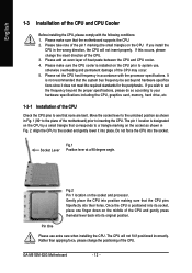
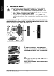
... and brand be installed in only one direction. Please make sure that the memory used . 2. GA-M51GM-S2G Motherboard - 14 - Before installing or removing memory modules, please make sure that the computer power is supported by the motherboard. A memory module can be inserted only in one direction. The memory capacity used...design. Fig.2 Close the plastic clip at both edges of the DIMM sockets to insert the module, please switch the direction. The motherboard supports DDR II memory modules, whereby BIOS will automatically detect memory capacity and specifications.
... and brand be installed in only one direction. Please make sure that the memory used . 2. GA-M51GM-S2G Motherboard - 14 - Before installing or removing memory modules, please make sure that the computer power is supported by the motherboard. A memory module can be inserted only in one direction. The memory capacity used...design. Fig.2 Close the plastic clip at both edges of the DIMM sockets to insert the module, please switch the direction. The motherboard supports DDR II memory modules, whereby BIOS will automatically detect memory capacity and specifications.
Manual
Page 15
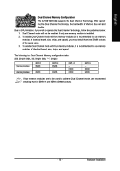
.../SS DDR II 4 - DS/SS DDR II 2 DS/SS - The following is installed. 2. Dual Channel mode will add double. English Dual Channel Memory Configuration The GA-M51GM-S2G supports the Dual Channel Technology. After operating the Dual Channel Technology, the bandwidth of the same color. 3.
.../SS DDR II 4 - DS/SS DDR II 2 DS/SS - The following is installed. 2. Dual Channel mode will add double. English Dual Channel Memory Configuration The GA-M51GM-S2G supports the Dual Channel Technology. After operating the Dual Channel Technology, the bandwidth of the same color. 3.
Manual
Page 17
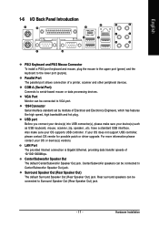
... can be connected to serial-based mouse or data processing devices. have a standard USB interface. Also make sure your OS does not support USB controller, please contact OS vendor for possible patch or driver upgrade. Center/Subwoofer Speaker Out The default Center/Subwoofer Speaker Out jack.... Rear surround speakers can be connected to the lower port (purple). For more information please contact your OS supports USB controller. Surround Speaker Out (Rear Speaker Out) The default Surround Speaker Out (Rear Speaker Out) jack. LAN Port The provided ...
... can be connected to serial-based mouse or data processing devices. have a standard USB interface. Also make sure your OS does not support USB controller, please contact OS vendor for possible patch or driver upgrade. Center/Subwoofer Speaker Out The default Center/Subwoofer Speaker Out jack.... Rear surround speakers can be connected to the lower port (purple). For more information please contact your OS supports USB controller. Surround Speaker Out (Rear Speaker Out) The default Surround Speaker Out (Rear Speaker Out) jack. LAN Port The provided ...
Manual
Page 20
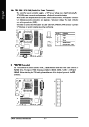
The types of the foolproof groove in the FDD connector. 34 33 2 1 GA-M51GM-S2G Motherboard - 20 - The black connector wire is used to connect the FDD cable while the other end of the cable connects to prevent CPU damage ... the CPU/system fan cable to the CPU_FAN/SYS_FAN connector to the FDD drive. Before attaching the FDD cable, please take note of FDD drives supported are designed with color-coded power connector wires. A red power connector wire indicates a positive connection and requires a +12V power voltage. English 3/4) CPU_FAN / SYS_FAN (Cooler Fan...
The types of the foolproof groove in the FDD connector. 34 33 2 1 GA-M51GM-S2G Motherboard - 20 - The black connector wire is used to connect the FDD cable while the other end of the cable connects to prevent CPU damage ... the CPU/system fan cable to the CPU_FAN/SYS_FAN connector to the FDD drive. Before attaching the FDD cable, please take note of FDD drives supported are designed with color-coded power connector wires. A red power connector wire indicates a positive connection and requires a +12V power voltage. English 3/4) CPU_FAN / SYS_FAN (Cooler Fan...
Manual
Page 23
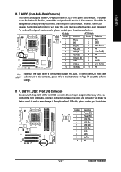
... connector, please refer to work or even damage it . If you wish to use the front audio function, connect the front panel audio module to support HD Audio. Incorrect connection between the cable and connector will make the device unable to work or even damage it . Definition Pin No. To connect... your chassis manufacturer. Check the pin assignment carefully while you connect the front panel audio module. English 10) F_AUDIO (Front Audio Panel Connector) This connector supports either HD (High Definition) or AC97 front panel audio module.
... connector, please refer to work or even damage it . If you wish to use the front audio function, connect the front panel audio module to support HD Audio. Incorrect connection between the cable and connector will make the device unable to work or even damage it . Definition Pin No. To connect... your chassis manufacturer. Check the pin assignment carefully while you connect the front panel audio module. English 10) F_AUDIO (Front Audio Panel Connector) This connector supports either HD (High Definition) or AC97 front panel audio module.
Manual
Page 32
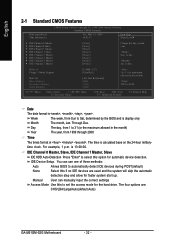
... Save ESC: Exit F7: Optimized Defaults F1: General Help Date The date format is calculated base on the 24-hour military- Drive A Floppy 3 Mode Support Halt On Base Memory Extended Memory Total Memory [1.44M, 3.5"] [Disabled] [All, But Keyboard] 640K 511M 512M 1 to 31 (or maximum allowed in... Sun to automatically detect IDE devices during POST(default) None Select this if no IDE devices are : CHS/LBA/Large/Auto(default:Auto) GA-M51GM-S2G Motherboard - 32 - IDE Device Setup. The four options are used and the system will skip the automatic detection step and allow for automatic...
... Save ESC: Exit F7: Optimized Defaults F1: General Help Date The date format is calculated base on the 24-hour military- Drive A Floppy 3 Mode Support Halt On Base Memory Extended Memory Total Memory [1.44M, 3.5"] [Disabled] [All, But Keyboard] 640K 511M 512M 1 to 31 (or maximum allowed in... Sun to automatically detect IDE devices during POST(default) None Select this if no IDE devices are : CHS/LBA/Large/Auto(default:Auto) GA-M51GM-S2G Motherboard - 32 - IDE Device Setup. The four options are used and the system will skip the automatic detection step and allow for automatic...
Manual
Page 33
... no SATA IDE devices are used and the system will be labeled on this to automatically detect SATA IDE devices during power up . Floppy 3 Mode Support (for a keyboard error; You can use one of currently installed hard disk. All, But Keyboard The system boot will not stop for faster system start...
... no SATA IDE devices are used and the system will be labeled on this to automatically detect SATA IDE devices during power up . Floppy 3 Mode Support (for a keyboard error; You can use one of currently installed hard disk. All, But Keyboard The system boot will not stop for faster system start...
Manual
Page 37
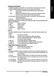
...: Exit F1: General Help F7: Optimized Defaults USB Configuration CMOS Setup Utility-Copyright (C) 1984-2006 Award Software USB Configuration On-Chip USB USB Keyboard Support USB Mouse Support [V1.1+V2.0] [Disabled] [Disabled] Item Help Menu Level` KLJI: Move Enter: Select F5: Previous Values +/-/PU/PD: Value F10: Save F6: Fail-Safe Defaults...
...: Exit F1: General Help F7: Optimized Defaults USB Configuration CMOS Setup Utility-Copyright (C) 1984-2006 Award Software USB Configuration On-Chip USB USB Keyboard Support USB Mouse Support [V1.1+V2.0] [Disabled] [Disabled] Item Help Menu Level` KLJI: Move Enter: Select F5: Previous Values +/-/PU/PD: Value F10: Save F6: Fail-Safe Defaults...
Manual
Page 38
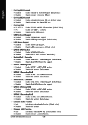
... port. (Default value) Disabled Disable onboard 1st channel IDE port. Disabled Disable USB keyboard support. (Default value) USB Mouse Support Enabled Disabled Enable USB mouse support. On-Chip USB V1.1+V2.0 V1.1 Disabled Enable USB 1.1 and USB 2.0 controllers. ... Enable Serial-ATAII 2 controller support. (Default Value) Disable Serial-ATAII 2 controller support. USB Keyboard Support Enabled Enable USB keyboard support. Disabled Disable this function. SATA-II 1 Primary RAID Enabled Enable SATAII 1 1st SATA RAID function. GA-M51GM-S2G Motherboard - 38 - Onboard LAN...
... port. (Default value) Disabled Disable onboard 1st channel IDE port. Disabled Disable USB keyboard support. (Default value) USB Mouse Support Enabled Disabled Enable USB mouse support. On-Chip USB V1.1+V2.0 V1.1 Disabled Enable USB 1.1 and USB 2.0 controllers. ... Enable Serial-ATAII 2 controller support. (Default Value) Disable Serial-ATAII 2 controller support. USB Keyboard Support Enabled Enable USB keyboard support. Disabled Disable this function. SATA-II 1 Primary RAID Enabled Enable SATAII 1 1st SATA RAID function. GA-M51GM-S2G Motherboard - 38 - Onboard LAN...
Manual
Page 45
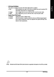
... speed depending on the CPU you use a CPU fan with Easy Tune based on their requirements. (Note) Whether the CPU Smart FAN Control function is supported will depend on system temperature. Users can adjust the fan speed with a 4-pin fan power cable. PWM Set to Voltage when you install. - 45 - BIOS...
... speed depending on the CPU you use a CPU fan with Easy Tune based on their requirements. (Note) Whether the CPU Smart FAN Control function is supported will depend on system temperature. Users can adjust the fan speed with a 4-pin fan power cable. PWM Set to Voltage when you install. - 45 - BIOS...
Manual
Page 49
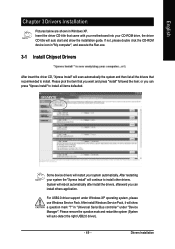
... will show the installation guide. Some device drivers will restart your system the "Xpress Install" will auto start and show a question mark "?" For USB2.0 driver support under "Device Manager". After restarting your system automatically. Drivers Installation Please pick the item that you can press "Xpress Install" to install. or you can...
... will show the installation guide. Some device drivers will restart your system the "Xpress Install" will auto start and show a question mark "?" For USB2.0 driver support under "Device Manager". After restarting your system automatically. Drivers Installation Please pick the item that you can press "Xpress Install" to install. or you can...
Manual
Page 54
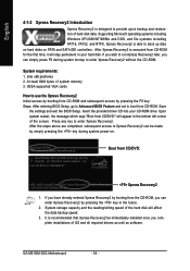
... you wish to run Xpress Recovery2 later, you can enter Xpress Recovery2 by pressing the key in the future. 2. VESA-supported VGA cards How to use the Xpress Recovery2 Initial access by booting from CD-ROM and subsequent access by pressing the F9 .... System requirements: 1. GA-M51GM-S2G Motherboard - 54 - English 4-1-2 Xpress Recovery2 Introduction Xpress Recovery2 is able to back up data on hard disks on . . . At least 64M bytes of hard disk data. Intel 945 BIOS for the first time, it will affect the data backup speed. 3. Supporting Microsoft operating systems including ...
... you wish to run Xpress Recovery2 later, you can enter Xpress Recovery2 by pressing the key in the future. 2. VESA-supported VGA cards How to use the Xpress Recovery2 Initial access by booting from CD-ROM and subsequent access by pressing the F9 .... System requirements: 1. GA-M51GM-S2G Motherboard - 54 - English 4-1-2 Xpress Recovery2 Introduction Xpress Recovery2 is able to back up data on hard disks on . . . At least 64M bytes of hard disk data. Intel 945 BIOS for the first time, it will affect the data backup speed. 3. Supporting Microsoft operating systems including ...
Manual
Page 55
...backup file.) 2. RESTORE: Restore the backed-up data to execute the EnableBigLba.exe program from hard disk. 3. USB hard disks are currently not supported. 6. It is normal that data backup takes longer time than 128G under Windows 2000, be allocated in advance. (A minimum 4GB is no backup ...the use of backing up ) 4. mended but the actual space is dependent on Nvidia chipsets, BIOS update is as follows: a. Does not support RAID/AHCI (class code 0104/0106) hard disks. 7. Hard disks detection sequence is required for the backup file must be backed up and ...
...backup file.) 2. RESTORE: Restore the backed-up data to execute the EnableBigLba.exe program from hard disk. 3. USB hard disks are currently not supported. 6. It is normal that data backup takes longer time than 128G under Windows 2000, be allocated in advance. (A minimum 4GB is no backup ...the use of backing up ) 4. mended but the actual space is dependent on Nvidia chipsets, BIOS update is as follows: a. Does not support RAID/AHCI (class code 0104/0106) hard disks. 7. Hard disks detection sequence is required for the backup file must be backed up and ...
Manual
Page 56
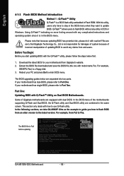
...Flash / F9 For Xpress Recovery 08/07/2003-i875P-6A79BG03C-00 GA-M51GM-S2G Motherboard - 56 - Part One: Updating BIOS with how to stay in Flash ROM. With this utility, users only have to use Q-Flash utility. Please note that Gigabyte Technology Co., Ltd is not responsible for 8KNXP Ultra Fa3 Check ...and operating system since it with model name.Fxx. Intel i875P AGPset BIOS for damages of system because of incorrect manipulation of the motherboards supporting Q-Flash and Dual BIOS, the Q-Flash utility and Dual BIOS utility are combined in the BIOS menu. We are sorry that because ...
...Flash / F9 For Xpress Recovery 08/07/2003-i875P-6A79BG03C-00 GA-M51GM-S2G Motherboard - 56 - Part One: Updating BIOS with how to stay in Flash ROM. With this utility, users only have to use Q-Flash utility. Please note that Gigabyte Technology Co., Ltd is not responsible for 8KNXP Ultra Fa3 Check ...and operating system since it with model name.Fxx. Intel i875P AGPset BIOS for damages of system because of incorrect manipulation of the motherboards supporting Q-Flash and Dual BIOS, the Q-Flash utility and Dual BIOS utility are combined in the BIOS menu. We are sorry that because ...
Manual
Page 64
It can help you need cannot be found in BIOS unzip file are supported. 2. In method II, be selected, please make sure your motherboard's model name again. IV. II. Otherwise, your motherboard's. In method I, if it according to ...ROM are the same as your system won't boot. GA-M51GM-S2G Motherboard - 64 - Please note that motherboard's model name in @BIOSTM server, please go onto Gigabyte's website for downloading and updating it shows two or more motherboard's model names to method II. Check out supported motherboard and Flash ROM: In the very beginning, ...
It can help you need cannot be found in BIOS unzip file are supported. 2. In method II, be selected, please make sure your motherboard's model name again. IV. II. Otherwise, your motherboard's. In method I, if it according to ...ROM are the same as your system won't boot. GA-M51GM-S2G Motherboard - 64 - Please note that motherboard's model name in @BIOSTM server, please go onto Gigabyte's website for downloading and updating it shows two or more motherboard's model names to method II. Check out supported motherboard and Flash ROM: In the very beginning, ...

Manual
Page 69
Press F10 to enter RAID setup utility" (Figure 6). The supported RAID modes include Mirroring (default), Striping, Stripe Mirroring, Spanning and Raid 5. Define a New Array - Step 1: After the POST memory test begins and before the operating ...
Press F10 to enter RAID setup utility" (Figure 6). The supported RAID modes include Mirroring (default), Striping, Stripe Mirroring, Spanning and Raid 5. Define a New Array - Step 1: After the POST memory test begins and before the operating ...
Manual
Page 72
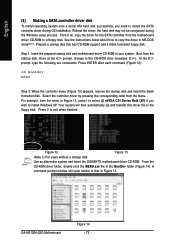
...ROM drive (example: D:\>). GA-M51GM-S2G Motherboard Figure 14 - 72 - Without the driver, the hard disk may not be recognized during OS installation. Boot from the motherboard driver CD-ROM to a floppy disk. Your system will open similar to that has CD-ROM support and a blank formatted floppy...in MS-DOS mode(Note1). Figure 12 Figure 13 (Note 1) For users without a startup disk: Use an alternative system and insert the GIGABYTE motherboard driver CD-ROM. At the D:\> prompt, type the following two commands. English (4) Making a SATA controller driver disk To install operating...
...ROM drive (example: D:\>). GA-M51GM-S2G Motherboard Figure 14 - 72 - Without the driver, the hard disk may not be recognized during OS installation. Boot from the motherboard driver CD-ROM to a floppy disk. Your system will open similar to that has CD-ROM support and a blank formatted floppy...in MS-DOS mode(Note1). Figure 12 Figure 13 (Note 1) For users without a startup disk: Use an alternative system and insert the GIGABYTE motherboard driver CD-ROM. At the D:\> prompt, type the following two commands. English (4) Making a SATA controller driver disk To install operating...

