Manual
Page 4
Table of Contents ItemChecklist ...6 OptionalAccessories ...6 GA-M51GM-S2G Motherboard Layout 7 Block Diagram ...8 Chapter 1 Hardware Installation 9 1-1 Considerations Prior to Installation 9 1-2 Feature Summary 10 1-3 Installation of the CPU and CPU Cooler 12 1-3-1 Installation of the CPU 12 1-3-2 Installation of the CPU cooler 13 1-4 Installation of Memory 14 1-5 Installation of Expansion Cards 16 1-6 I/O Back Panel Introduction 17 1-7 Connectors Introduction 18 Chapter...
Table of Contents ItemChecklist ...6 OptionalAccessories ...6 GA-M51GM-S2G Motherboard Layout 7 Block Diagram ...8 Chapter 1 Hardware Installation 9 1-1 Considerations Prior to Installation 9 1-2 Feature Summary 10 1-3 Installation of the CPU and CPU Cooler 12 1-3-1 Installation of the CPU 12 1-3-2 Installation of the CPU cooler 13 1-4 Installation of Memory 14 1-5 Installation of Expansion Cards 16 1-6 I/O Back Panel Introduction 17 1-7 Connectors Introduction 18 Chapter...

Manual
Page 8
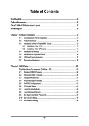
Block Diagram PCI-ECLK (100MHz) VGA PCI Express x 16 PCI-ECLK x 1 (100MHz) 1 PCI Express x 1 LAN RJ45 Marvell 88E1116 PCI Bus TSB43AB23 AMD Socket AM2 CPU CPUCLK+/-(200MHz) DDRII 800/667/533/400MHz DIMM Dual Channel Memory Hyper Transport Bus nVIDIA® GeForce 6100 nVIDIA® nForce 430 ATA33/66/100/133 IDE Channels 4 SATA 3Gb/s BIOS LPC BUS IT8716 Floppy LPT Port COM Ports CODEC PS/2 KB/Mouse 2PCI PCICLK (33MHz) 8 USB Ports 3 IEEE1394a Surround Speaker Out Center/Subwoofer Speaker Out Side Speaker Out MIC Line-Out Line-In SPDIF In SPDIF Out - 8 -
Block Diagram PCI-ECLK (100MHz) VGA PCI Express x 16 PCI-ECLK x 1 (100MHz) 1 PCI Express x 1 LAN RJ45 Marvell 88E1116 PCI Bus TSB43AB23 AMD Socket AM2 CPU CPUCLK+/-(200MHz) DDRII 800/667/533/400MHz DIMM Dual Channel Memory Hyper Transport Bus nVIDIA® GeForce 6100 nVIDIA® nForce 430 ATA33/66/100/133 IDE Channels 4 SATA 3Gb/s BIOS LPC BUS IT8716 Floppy LPT Port COM Ports CODEC PS/2 KB/Mouse 2PCI PCICLK (33MHz) 8 USB Ports 3 IEEE1394a Surround Speaker Out Center/Subwoofer Speaker Out Side Speaker Out MIC Line-Out Line-In SPDIF In SPDIF Out - 8 -

Manual
Page 9
..., please consult a certified computer technician. Prior to wear an electrostatic discharge (ESD) cuff when handling electronic components (CPU, RAM). 4. Please do not allow screws to Installation Preparing Your Computer The motherboard contains numerous delicate electronic circuits and...the permitted parameters. 6. Product determined to use of Non-Warranty 1. Instances of uncertified components. 5. Damage due to be an unofficial Gigabyte product. - 9 - English Chapter 1 Hardware Installation 1-1 Considerations Prior to come in contact with the motherboard circuit or its power ...
..., please consult a certified computer technician. Prior to wear an electrostatic discharge (ESD) cuff when handling electronic components (CPU, RAM). 4. Please do not allow screws to Installation Preparing Your Computer The motherboard contains numerous delicate electronic circuits and...the permitted parameters. 6. Product determined to use of Non-Warranty 1. Instances of uncertified components. 5. Damage due to be an unofficial Gigabyte product. - 9 - English Chapter 1 Hardware Installation 1-1 Considerations Prior to come in contact with the motherboard circuit or its power ...
Manual
Page 10
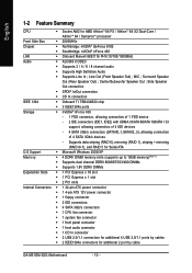
... connector Š 1 front panel connector Š 1 front audio connector Š 1 CD In connector Š 2 USB 2.0/1.1 connectors for additional 4 USB 2.0/1.1 ports by cable GA-M51GM-S2G Motherboard - 10 - MIC ; English 1-2 Feature Summary CPU Š Socket AM2 for additional 2 port by cables Š 2 IEEE1394a connectors for AMD AthlonTM 64 FX / AthlonTM 64 X2 Dual-Core / AthlonTM...
... connector Š 1 front panel connector Š 1 front audio connector Š 1 CD In connector Š 2 USB 2.0/1.1 connectors for additional 4 USB 2.0/1.1 ports by cable GA-M51GM-S2G Motherboard - 10 - MIC ; English 1-2 Feature Summary CPU Š Socket AM2 for additional 2 port by cables Š 2 IEEE1394a connectors for AMD AthlonTM 64 FX / AthlonTM 64 X2 Dual-Core / AthlonTM...
Manual
Page 11
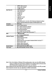
... Speaker Out) I/O Control Š IT8716 chip Hardware Monitor Š System voltage detection Š CPU / System temperature detection Š CPU / System fan speed detection Š CPU warning temperature Š CPU / System fan failure warning Š Supports CPU / System Smart Fan function(Note 2) BIOS Š 1 4Mbit flash ROM Š Use of... is supported will be less than 4GB; Windows 64-bit operating system doesn't have such limitation. (Note 2) Whether the CPU Smart FAN Control function is installed, the actual memory available for the operating system will depend on the...
... Speaker Out) I/O Control Š IT8716 chip Hardware Monitor Š System voltage detection Š CPU / System temperature detection Š CPU / System fan speed detection Š CPU warning temperature Š CPU / System fan failure warning Š Supports CPU / System Smart Fan function(Note 2) BIOS Š 1 4Mbit flash ROM Š Use of... is supported will be less than 4GB; Windows 64-bit operating system doesn't have such limitation. (Note 2) Whether the CPU Smart FAN Control function is installed, the actual memory available for the operating system will depend on the...
Manual
Page 12
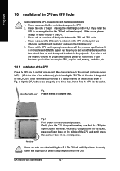
...Socket Lever Fig.1 Position lever at a 90 degree angle. GA-M51GM-S2G Motherboard - 12 - Align the CPU to system use extra care when installing the CPU. Do not force the CPU into place. Please make sure that the CPU pins fitperfectly into its socket, place one finger down on the...specifications, please do so according to your hardware specifications including the CPU, graphics card, memory, hard drive, etc. 1-3-1 Installation of the CPU Check the CPU pins to inserting the CPU. Once the CPU is designated on the CPU by a small triangle that none are bent. If this occurs,...
...Socket Lever Fig.1 Position lever at a 90 degree angle. GA-M51GM-S2G Motherboard - 12 - Align the CPU to system use extra care when installing the CPU. Do not force the CPU into place. Please make sure that the CPU pins fitperfectly into its socket, place one finger down on the...specifications, please do so according to your hardware specifications including the CPU, graphics card, memory, hard drive, etc. 1-3-1 Installation of the CPU Check the CPU pins to inserting the CPU. Once the CPU is designated on the CPU by a small triangle that none are bent. If this occurs,...

Manual
Page 13
... adhere to the heat sink manual for heat dissipation or using extreme care when removing the CPU cooler. - 13 - English 1-3-2 Installation of the CPU cooler Fig.1 Before installing the CPU cooler, please first add an even layer of heat paste on the motherboard so that either... paste be used for detailed installation instructions). Hardware Installation Fig.2 Please connect the CPU cooler power connector to prevent CPU overheating. To prevent such an occurrence, it is suggested that the CPU cooler can properly function to the CPU_FAN connector located on the surface of the ...
... adhere to the heat sink manual for heat dissipation or using extreme care when removing the CPU cooler. - 13 - English 1-3-2 Installation of the CPU cooler Fig.1 Before installing the CPU cooler, please first add an even layer of heat paste on the motherboard so that either... paste be used for detailed installation instructions). Hardware Installation Fig.2 Please connect the CPU cooler power connector to prevent CPU overheating. To prevent such an occurrence, it is suggested that the CPU cooler can properly function to the CPU_FAN connector located on the surface of the ...
Manual
Page 15
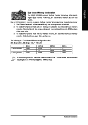
... Side, "--": Empty) 2 memory modules 4 memory modules DDR II 1 DS/SS - DS/SS DS/SS DDR II 4 - English Dual Channel Memory Configuration The GA-M51GM-S2G supports the Dual Channel Technology. Hardware Installation Due to CPU limitation, if you must install them in DDRII 1 and DDRII 2 DIMM sockets. - 15 - DS/SS DDR II 2 DS/SS -
... Side, "--": Empty) 2 memory modules 4 memory modules DDR II 1 DS/SS - DS/SS DS/SS DDR II 4 - English Dual Channel Memory Configuration The GA-M51GM-S2G supports the Dual Channel Technology. Hardware Installation Due to CPU limitation, if you must install them in DDRII 1 and DDRII 2 DIMM sockets. - 15 - DS/SS DDR II 2 DS/SS -

Manual
Page 19
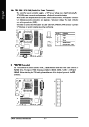
... unstable system or a system that does not provide the required power, the result can withstand high power consumption be used that is able to the CPU. Definition 2 1 1 GND 4 3 2 GND 3 +12V 4 +12V Pin No. Hardware Installation The ATX_12V power connector mainly supplies power to handle the system voltage requirements. Pin No. If...
... unstable system or a system that does not provide the required power, the result can withstand high power consumption be used that is able to the CPU. Definition 2 1 1 GND 4 3 2 GND 3 +12V 4 +12V Pin No. Hardware Installation The ATX_12V power connector mainly supplies power to handle the system voltage requirements. Pin No. If...
Manual
Page 20
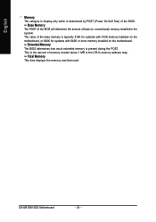
...-coded power connector wires. The black connector wire is used to connect the FDD cable while the other end of the cable connects to prevent CPU damage or system hanging caused by overheating. 1 CPU_FAN 1 SYS_FAN Pin No. 1 2 3 4 Definition GND +12V Sense Speed Control (Only for...cable, please take note of the foolproof groove in the FDD connector. 34 33 2 1 GA-M51GM-S2G Motherboard - 20 - A red power connector wire indicates a positive connection and requires a +12V power voltage. Remember to connect the CPU/system fan cable to the CPU_FAN/SYS_FAN connector to the FDD drive.
...-coded power connector wires. The black connector wire is used to connect the FDD cable while the other end of the cable connects to prevent CPU damage or system hanging caused by overheating. 1 CPU_FAN 1 SYS_FAN Pin No. 1 2 3 4 Definition GND +12V Sense Speed Control (Only for...cable, please take note of the foolproof groove in the FDD connector. 34 33 2 1 GA-M51GM-S2G Motherboard - 20 - A red power connector wire indicates a positive connection and requires a +12V power voltage. Remember to connect the CPU/system fan cable to the CPU_FAN/SYS_FAN connector to the FDD drive.
Manual
Page 34
... This item displays the memory size that used. This is determined by POST (Power On Self Test) of base (or conventional) memory installed in the CPU's memory address map. GA-M51GM-S2G Motherboard - 34 - Base Memory The POST of the BIOS will determine the amount of the BIOS.
... This item displays the memory size that used. This is determined by POST (Power On Self Test) of base (or conventional) memory installed in the CPU's memory address map. GA-M51GM-S2G Motherboard - 34 - Base Memory The POST of the BIOS will determine the amount of the BIOS.
Manual
Page 44
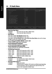
... next boot. Enabled When this function is enabled, CPU fan will restart. CPU Warning Temperature 60oC / 140oF 70oC / 158oF 80oC / 176oF 90oC / 194oF Monitor CPU temperature at 70oC / 158oF. Monitor CPU temperature at 60oC / 140oF. Monitor CPU temperature at different speed depending on their requirements. (Default value) GA-M51GM-S2G Motherboard - 44 - Case Opened If the case is...
... next boot. Enabled When this function is enabled, CPU fan will restart. CPU Warning Temperature 60oC / 140oF 70oC / 158oF 80oC / 176oF 90oC / 194oF Monitor CPU temperature at 70oC / 158oF. Monitor CPU temperature at 60oC / 140oF. Monitor CPU temperature at different speed depending on their requirements. (Default value) GA-M51GM-S2G Motherboard - 44 - Case Opened If the case is...
Manual
Page 45
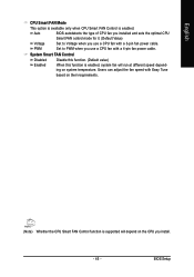
... FAN control mode for it. (Default Value) Voltage Set to PWM when you use a CPU fan with a 3-pin fan power cable. System Smart FAN Control Disabled Disable this function. (Default value) Enabled When this function is enabled, system fan will ... fan power cable. PWM Set to Voltage when you use a CPU fan with Easy Tune based on their requirements. (Note) Whether the CPU Smart FAN Control function is enabled. BIOS Setup English CPU Smart FAN Mode This option is available only when CPU Smart FAN Control is supported will run at different speed depending...
... FAN control mode for it. (Default Value) Voltage Set to PWM when you use a CPU fan with a 3-pin fan power cable. System Smart FAN Control Disabled Disable this function. (Default value) Enabled When this function is enabled, system fan will ... fan power cable. PWM Set to Voltage when you use a CPU fan with Easy Tune based on their requirements. (Note) Whether the CPU Smart FAN Control function is enabled. BIOS Setup English CPU Smart FAN Mode This option is available only when CPU Smart FAN Control is supported will run at different speed depending...

Manual
Page 53
....A. setting page 3. Appendix Smart-Fan Enters the Smart-Fan setting page 4. PC Health Enters the PC Health setting page 5. GIGABYTE Logo Log on different motherboards. - 53 - Exit or Minimize button Quit or Minimize EasyTuneTM 5 software (Note) EasyTune 5 functions...the Overclocking setting page 2. Display screen Display panel of both CPU cooling fan and North-Bridge Chipset cooling fan, 4) PC health for enhancing system performance, 2) C.I .B. Featuring several powerful yet easy to GIGABYTE website 10. English Chapter 4 Appendix 4-1 Unique Software Utilities ...
....A. setting page 3. Appendix Smart-Fan Enters the Smart-Fan setting page 4. PC Health Enters the PC Health setting page 5. GIGABYTE Logo Log on different motherboards. - 53 - Exit or Minimize button Quit or Minimize EasyTuneTM 5 software (Note) EasyTune 5 functions...the Overclocking setting page 2. Display screen Display panel of both CPU cooling fan and North-Bridge Chipset cooling fan, 4) PC health for enhancing system performance, 2) C.I .B. Featuring several powerful yet easy to GIGABYTE website 10. English Chapter 4 Appendix 4-1 Unique Software Utilities ...
Manual
Page 68
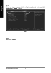
... 3: To boot from Windows installation CD-ROM, set First Boot Device under the Advanced BIOS Features menu to 3 No-Execute Memory Protect CPU Enhanced Halt (C1E) CPU Thermal Monitor 2(TM2) CPU EIST Function (µù) [Press Enter] [CDROM] [Hard Disk] [CDROM] [Setup] [Enabled] [Disabled] [Enabled] [Enabled] [Enabled] [Enabled] Item Help Menu Level... Utility-Copyright (C) 1984-2005 Award Software Advanced BIOS Features Hard Disk Boot Priority First Boot Device Second Boot Device Third Boot Device Password Check # CPU Hyper-Threading Limit CPUID Max. GA-M51GM-S2G Motherboard - 68 -
... 3: To boot from Windows installation CD-ROM, set First Boot Device under the Advanced BIOS Features menu to 3 No-Execute Memory Protect CPU Enhanced Halt (C1E) CPU Thermal Monitor 2(TM2) CPU EIST Function (µù) [Press Enter] [CDROM] [Hard Disk] [CDROM] [Setup] [Enabled] [Disabled] [Enabled] [Enabled] [Enabled] [Enabled] Item Help Menu Level... Utility-Copyright (C) 1984-2005 Award Software Advanced BIOS Features Hard Disk Boot Priority First Boot Device Second Boot Device Third Boot Device Password Check # CPU Hyper-Threading Limit CPUID Max. GA-M51GM-S2G Motherboard - 68 -


