Manual
Page 4
Table of Contents ItemChecklist ...6 OptionalAccessories ...6 GA-M51GM-S2G Motherboard Layout 7 Block Diagram ...8 Chapter 1 Hardware Installation 9 1-1 Considerations Prior to Installation 9 1-2 Feature Summary 10 1-3 Installation of the CPU and CPU Cooler 12 1-3-1 Installation of the CPU 12 1-3-2 Installation of the CPU cooler 13 1-4 Installation of Memory 14 1-5 Installation of Expansion Cards 16 1-6 I/O Back Panel Introduction 17 1-7 Connectors...
Table of Contents ItemChecklist ...6 OptionalAccessories ...6 GA-M51GM-S2G Motherboard Layout 7 Block Diagram ...8 Chapter 1 Hardware Installation 9 1-1 Considerations Prior to Installation 9 1-2 Feature Summary 10 1-3 Installation of the CPU and CPU Cooler 12 1-3-1 Installation of the CPU 12 1-3-2 Installation of the CPU cooler 13 1-4 Installation of Memory 14 1-5 Installation of Expansion Cards 16 1-6 I/O Back Panel Introduction 17 1-7 Connectors...

Manual
Page 8
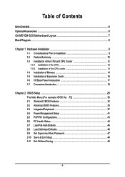
Block Diagram PCI-ECLK (100MHz) VGA PCI Express x 16 PCI-ECLK x 1 (100MHz) 1 PCI Express x 1 LAN RJ45 Marvell 88E1116 PCI Bus TSB43AB23 AMD Socket AM2 CPU CPUCLK+/-(200MHz) DDRII 800/667/533/400MHz DIMM Dual Channel Memory Hyper Transport Bus nVIDIA® GeForce 6100 nVIDIA® nForce 430 ATA33/66/100/133 IDE Channels 4 SATA 3Gb/s BIOS LPC BUS IT8716 Floppy LPT Port COM Ports CODEC PS/2 KB/Mouse 2PCI PCICLK (33MHz) 8 USB Ports 3 IEEE1394a Surround Speaker Out Center/Subwoofer Speaker Out Side Speaker Out MIC Line-Out Line-In SPDIF In SPDIF Out - 8 -
Block Diagram PCI-ECLK (100MHz) VGA PCI Express x 16 PCI-ECLK x 1 (100MHz) 1 PCI Express x 1 LAN RJ45 Marvell 88E1116 PCI Bus TSB43AB23 AMD Socket AM2 CPU CPUCLK+/-(200MHz) DDRII 800/667/533/400MHz DIMM Dual Channel Memory Hyper Transport Bus nVIDIA® GeForce 6100 nVIDIA® nForce 430 ATA33/66/100/133 IDE Channels 4 SATA 3Gb/s BIOS LPC BUS IT8716 Floppy LPT Port COM Ports CODEC PS/2 KB/Mouse 2PCI PCICLK (33MHz) 8 USB Ports 3 IEEE1394a Surround Speaker Out Center/Subwoofer Speaker Out Side Speaker Out MIC Line-Out Line-In SPDIF In SPDIF Out - 8 -
Manual
Page 10
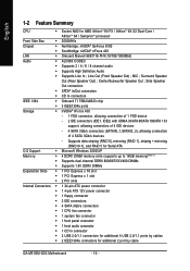
... Summary CPU Š Socket AM2 for additional 2 port by cable GA-M51GM-S2G Motherboard - 10 - Supports data striping (RAID 0), mirroring (RAID 1), striping + mirroring (RAID 0+1), and RAID 5 for Serial ATA O.S Support Š Microsoft Windows 2000/XP Memory Š 4 DDRII DIMM memory slots (supports up to 16GB memory)(Note 1) Š Supports dual channel DDRII 800/667/533/400...
... Summary CPU Š Socket AM2 for additional 2 port by cable GA-M51GM-S2G Motherboard - 10 - Supports data striping (RAID 0), mirroring (RAID 1), striping + mirroring (RAID 0+1), and RAID 5 for Serial ATA O.S Support Š Microsoft Windows 2000/XP Memory Š 4 DDRII DIMM memory slots (supports up to 16GB memory)(Note 1) Š Supports dual channel DDRII 800/667/533/400...
Manual
Page 11
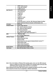
Hardware Installation Windows 64-bit operating system doesn't have such limitation. (Note 2) Whether the CPU Smart FAN Control function is installed, the actual memory available for the operating system will depend on the CPU you install. (Note 3) EasyTune functions may vary depending on different motherboards. - 11 - English Š 1 SPDIF ...; Micro ATX form factor; 24.4cm x 24.4cm (Note 1) Due to the limitation of Windows 32-bit operating system, when more than 4GB of physical memory is supported will be less than 4GB;
Hardware Installation Windows 64-bit operating system doesn't have such limitation. (Note 2) Whether the CPU Smart FAN Control function is installed, the actual memory available for the operating system will depend on the CPU you install. (Note 3) EasyTune functions may vary depending on different motherboards. - 11 - English Š 1 SPDIF ...; Micro ATX form factor; 24.4cm x 24.4cm (Note 1) Due to the limitation of Windows 32-bit operating system, when more than 4GB of physical memory is supported will be less than 4GB;
Manual
Page 12
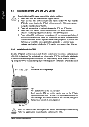
...of the CPU. It is positioned into place. Fig.2 Pin 1 location on the CPU. Socket Lever Fig.1 Position lever at a 90 degree angle. GA-M51GM-S2G Motherboard - 12 - Please make sure the CPU cooler is designated on the CPU by a small triangle that the motherboard supports the CPU. 2. Please...that the system bus frequency be set beyond the proper specifications, please do so according to your hardware specifications including the CPU, graphics card, memory, hard drive, etc. 1-3-1 Installation of the CPU Check the CPU pins to inserting the CPU. Align the CPU to system use extra...
...of the CPU. It is positioned into place. Fig.2 Pin 1 location on the CPU. Socket Lever Fig.1 Position lever at a 90 degree angle. GA-M51GM-S2G Motherboard - 12 - Please make sure the CPU cooler is designated on the CPU by a small triangle that the motherboard supports the CPU. 2. Please...that the system bus frequency be set beyond the proper specifications, please do so according to your hardware specifications including the CPU, graphics card, memory, hard drive, etc. 1-3-1 Installation of the CPU Check the CPU pins to inserting the CPU. Align the CPU to system use extra...
Manual
Page 14
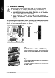
... installation steps when you are designed so that the computer power is supported by the motherboard. GA-M51GM-S2G Motherboard - 14 - Memory modules have a foolproof insertion design. Notch DDR II Fig.1 The DIMM socket has a notch, so the DIMM memory module can be inserted only in one direction. Fig.2 Close the plastic clip at both...
... installation steps when you are designed so that the computer power is supported by the motherboard. GA-M51GM-S2G Motherboard - 14 - Memory modules have a foolproof insertion design. Notch DDR II Fig.1 The DIMM socket has a notch, so the DIMM memory module can be inserted only in one direction. Fig.2 Close the plastic clip at both...
Manual
Page 15
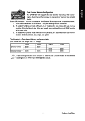
...The following is installed. 2. DS/SS DS/SS If two memory modules are to be enabled if only one memory module is a Dual Channel Memory configuration table: (DS: Double Side, SS: Single Side, "--": Empty) 2 memory modules 4 memory modules DDR II 1 DS/SS - To enable Dual Channel mode...sockets of identical brand, size, chips, and speed. Hardware Installation DS/SS DS/SS DDR II 4 - English Dual Channel Memory Configuration The GA-M51GM-S2G supports the Dual Channel Technology. After operating the Dual Channel Technology, the bandwidth of identical brand, size, chips, and speed),...
...The following is installed. 2. DS/SS DS/SS If two memory modules are to be enabled if only one memory module is a Dual Channel Memory configuration table: (DS: Double Side, SS: Single Side, "--": Empty) 2 memory modules 4 memory modules DDR II 1 DS/SS - To enable Dual Channel mode...sockets of identical brand, size, chips, and speed. Hardware Installation DS/SS DS/SS DDR II 4 - English Dual Channel Memory Configuration The GA-M51GM-S2G supports the Dual Channel Technology. After operating the Dual Channel Technology, the bandwidth of identical brand, size, chips, and speed),...
Manual
Page 32
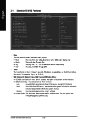
... clock. You can manually input the correct settings Access Mode Use this if no IDE devices are : CHS/LBA/Large/Auto(default:Auto) GA-M51GM-S2G Motherboard - 32 - English 2-1 Standard CMOS Features Date (mm:dd:yy) Time (hh:mm:ss) CMOS Setup Utility-Copyright (C) 1984-2006... Master, Slave, IDE Channel 1 Master, Slave IDE HDD Auto-Detection Press "Enter" to Dec. Drive A Floppy 3 Mode Support Halt On Base Memory Extended Memory Total Memory [1.44M, 3.5"] [Disabled] [All, But Keyboard] 640K 511M 512M 1 to 31 (or maximum allowed in the month) 1999 to automatically detect IDE...
... clock. You can manually input the correct settings Access Mode Use this if no IDE devices are : CHS/LBA/Large/Auto(default:Auto) GA-M51GM-S2G Motherboard - 32 - English 2-1 Standard CMOS Features Date (mm:dd:yy) Time (hh:mm:ss) CMOS Setup Utility-Copyright (C) 1984-2006... Master, Slave, IDE Channel 1 Master, Slave IDE HDD Auto-Detection Press "Enter" to Dec. Drive A Floppy 3 Mode Support Halt On Base Memory Extended Memory Total Memory [1.44M, 3.5"] [Disabled] [All, But Keyboard] 640K 511M 512M 1 to 31 (or maximum allowed in the month) 1999 to automatically detect IDE...
Manual
Page 34
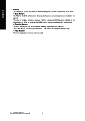
... amount of base (or conventional) memory installed in the CPU's memory address map. Extended Memory The BIOS determines how much extended memory is determined by POST (Power On Self Test) of memory located above 1 MB in the system. GA-M51GM-S2G Motherboard - 34 - Total Memory This item displays the memory size that used. English Memory The category is display-only which...
... amount of base (or conventional) memory installed in the CPU's memory address map. Extended Memory The BIOS determines how much extended memory is determined by POST (Power On Self Test) of memory located above 1 MB in the system. GA-M51GM-S2G Motherboard - 34 - Total Memory This item displays the memory size that used. English Memory The category is display-only which...

Manual
Page 53
Featuring several powerful yet easy to GIGABYTE website 10. setting page 3. Exit or Minimize button Quit or Minimize EasyTuneTM 5 software (Note) EasyTune 5 functions may vary depending on to use ...North-Bridge Chipset cooling fan, 4) PC health for enhancing system performance, 2) C.I .B. and M.I .B. for special enhancement for CPU and Memory, 3) Smart-Fan control for managing fan speed control of CPU frequency 8. GIGABYTE Logo Log on different motherboards. - 53 - Overclocking Enters the Overclocking setting page 2. "Easy Mode" & "Advance Mode" Toggles between...
Featuring several powerful yet easy to GIGABYTE website 10. setting page 3. Exit or Minimize button Quit or Minimize EasyTuneTM 5 software (Note) EasyTune 5 functions may vary depending on to use ...North-Bridge Chipset cooling fan, 4) PC health for enhancing system performance, 2) C.I .B. and M.I .B. for special enhancement for CPU and Memory, 3) Smart-Fan control for managing fan speed control of CPU frequency 8. GIGABYTE Logo Log on different motherboards. - 53 - Overclocking Enters the Overclocking setting page 2. "Easy Mode" & "Advance Mode" Toggles between...
Manual
Page 54
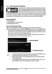
...BIOS for the first time, it will stay permanent in the bottom left corner of OS and all required drivers as well as software. GA-M51GM-S2G Motherboard - 54 - System requirements: 1. VESA-supported VGA cards How to use the Xpress Recovery2 Initial access by booting from CD-ROM ...-I945-6A79HG0GC-00 Xpress Recovery2 1. English 4-1-2 Xpress Recovery2 Introduction Xpress Recovery2 is designed to provide quick backup and restoration of system memory 3. After Xpress Recovery2 is executed from CD/DVD: Award Modular BIOS v6.00PG, An Energy Star Ally Copyright (C) 1984-2004, Award Software,...
...BIOS for the first time, it will stay permanent in the bottom left corner of OS and all required drivers as well as software. GA-M51GM-S2G Motherboard - 54 - System requirements: 1. VESA-supported VGA cards How to use the Xpress Recovery2 Initial access by booting from CD-ROM ...-I945-6A79HG0GC-00 Xpress Recovery2 1. English 4-1-2 Xpress Recovery2 Introduction Xpress Recovery2 is designed to provide quick backup and restoration of system memory 3. After Xpress Recovery2 is executed from CD/DVD: Award Modular BIOS v6.00PG, An Energy Star Ally Copyright (C) 1984-2004, Award Software,...
Manual
Page 56
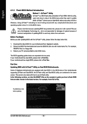
...-6A79BG03C-00 GA-M51GM-S2G Motherboard - 56 - For example, 8KNXPU.Fba) to use Q-Flash utility. The BIOS upgrading guides below first. 1. This section only deals with dual BIOS. Intel i875P AGPset BIOS for damages of system because of incorrect manipulation of Gigabyte motherboards are ...responsible for 8KNXP Ultra Fa3 Check System Health OK , VCore = 1.5250 Main Processor : Intel Pentium(R) 4 1.6GHz (133x12) Memory Testing : 131072K OK Memory Frequency 266 MHz in Single Channel Primary Master : FUJITSU MPE3170AT ED-03-08 Primary Slave : None Secondary Master : CREATIVEDVD-RM ...
...-6A79BG03C-00 GA-M51GM-S2G Motherboard - 56 - For example, 8KNXPU.Fba) to use Q-Flash utility. The BIOS upgrading guides below first. 1. This section only deals with dual BIOS. Intel i875P AGPset BIOS for damages of system because of incorrect manipulation of Gigabyte motherboards are ...responsible for 8KNXP Ultra Fa3 Check System Health OK , VCore = 1.5250 Main Processor : Intel Pentium(R) 4 1.6GHz (133x12) Memory Testing : 131072K OK Memory Frequency 266 MHz in Single Channel Primary Master : FUJITSU MPE3170AT ED-03-08 Primary Slave : None Secondary Master : CREATIVEDVD-RM ...
Manual
Page 59
... you exit Q-Flash. Intel i875P AGPset BIOS for 8KNXP Ultra Fba Check System Health OK , VCore = 1.5250 Main Processor : Intel Pentium(R) 4 1.6GHz (133x12) Memory Testing : 131072K OK Memory Frequency 266 MHz in Single Channel Primary Master : FUJITSU MPE3170AT ED-03-08 Primary Slave : None Secondary Master : CREATIVEDVD-RM DVD1242E BC101 Secondary Slave...
... you exit Q-Flash. Intel i875P AGPset BIOS for 8KNXP Ultra Fba Check System Health OK , VCore = 1.5250 Main Processor : Intel Pentium(R) 4 1.6GHz (133x12) Memory Testing : 131072K OK Memory Frequency 266 MHz in Single Channel Primary Master : FUJITSU MPE3170AT ED-03-08 Primary Slave : None Secondary Master : CREATIVEDVD-RM DVD1242E BC101 Secondary Slave...
Manual
Page 62
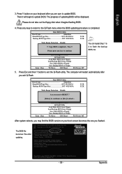
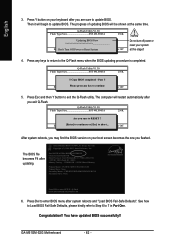
...oPppayss !! Intel 845GE AGPSet BIOS for 8GE800 F4 Check System Health OK Main Processor : Intel Pentium(R) 4 1.7GHz (100x17.0) Memory Testing : 122880K OK + 8192K Shared Memory Primary Master : FUJITSU MPE3170AT ED-03-08 Primary Slave : None Secondary Master : CREATIVEDVD-RM DVD1242E BC101 Secondary Slave : ...when the BIOS updating procedure is completed. Save BIOS to Floppy Please:Mporevses any keys to return to update BIOS. English 3. GA-M51GM-S2G Motherboard - 62 - Press any kEeySCto:Rceosnettinue F10:Power Off 5. Q-Flash Utility V1.30 Flash Type/Size SST 49LF003A 256K Keep...
...oPppayss !! Intel 845GE AGPSet BIOS for 8GE800 F4 Check System Health OK Main Processor : Intel Pentium(R) 4 1.7GHz (100x17.0) Memory Testing : 122880K OK + 8192K Shared Memory Primary Master : FUJITSU MPE3170AT ED-03-08 Primary Slave : None Secondary Master : CREATIVEDVD-RM DVD1242E BC101 Secondary Slave : ...when the BIOS updating procedure is completed. Save BIOS to Floppy Please:Mporevses any keys to return to update BIOS. English 3. GA-M51GM-S2G Motherboard - 62 - Press any kEeySCto:Rceosnettinue F10:Power Off 5. Q-Flash Utility V1.30 Flash Type/Size SST 49LF003A 256K Keep...
Manual
Page 68
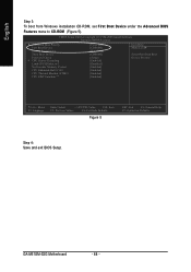
... CD-ROM (Figure 5). English Step 3: To boot from Windows installation CD-ROM, set First Boot Device under the Advanced BIOS Features menu to 3 No-Execute Memory Protect CPU Enhanced Halt (C1E) CPU Thermal Monitor 2(TM2) CPU EIST Function (µù) [Press Enter] [CDROM] [Hard Disk] [CDROM] [Setup] [Enabled] [Disabled] [Enabled] [Enabled...: Value F10: Save F5: Previous Values F6: Fail-Safe Defaults Figure 5 ESC: Exit F1: General Help F7: Optimized Defaults Step 4: Save and exit BIOS Setup. GA-M51GM-S2G Motherboard - 68 -
... CD-ROM (Figure 5). English Step 3: To boot from Windows installation CD-ROM, set First Boot Device under the Advanced BIOS Features menu to 3 No-Execute Memory Protect CPU Enhanced Halt (C1E) CPU Thermal Monitor 2(TM2) CPU EIST Function (µù) [Press Enter] [CDROM] [Hard Disk] [CDROM] [Setup] [Enabled] [Disabled] [Enabled] [Enabled...: Value F10: Save F5: Previous Values F6: Fail-Safe Defaults Figure 5 ESC: Exit F1: General Help F7: Optimized Defaults Step 4: Save and exit BIOS Setup. GA-M51GM-S2G Motherboard - 68 -

Manual
Page 69
... Array Disks Loc Disk Model [ ] Add Capacity [ ] Del [ESC] Quit [F6] Back [F7] Finish [TAB] Navigate [ ] Select [ENTER] Popup Figure 7 - 69 - Step 1: After the POST memory test begins and before the operating system boot begins, look for a message which says "Press F10 to Section 4 if you enter the NVIDIA RAID setup...
... Array Disks Loc Disk Model [ ] Add Capacity [ ] Del [ESC] Quit [F6] Back [F7] Finish [TAB] Navigate [ ] Select [ENTER] Popup Figure 7 - 69 - Step 1: After the POST memory test begins and before the operating system boot begins, look for a message which says "Press F10 to Section 4 if you enter the NVIDIA RAID setup...

Manual
Page 6
... an example of Striping Block size. Detecting array ... We recommend you do not want to create RAID. ¤¤ Step 1: ¤å After the POST memory test begins and before the operating system boot begins, look for a message which says "Press F10 to the default setting--Optimal (64K). Skip this step...
... an example of Striping Block size. Detecting array ... We recommend you do not want to create RAID. ¤¤ Step 1: ¤å After the POST memory test begins and before the operating system boot begins, look for a message which says "Press F10 to the default setting--Optimal (64K). Skip this step...


