User Manual
Page 6
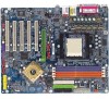
English Table of Contents Read Me First 4 Chapter 1 Introduction 8 Features Summary 8 GA-K8NS Ultra-939 Motherboard Layout 10 Block Diagram 11 Chapter 2 Hardware Installation Process 13 Step 1: Install the Central Processing Unit (CPU 14 Step 2: Install Memory Modules 16 Step 3: Install Expansion Cards 18 Step 4: Install I/O Peripherals Cables 19 Step 4-1: I/O Back Panel Introduction 19 ... BIOS Features 40 Integrated Peripherals 42 Power Management Setup 46 PnP/PCI Configurations 48 PC Health Status 49 MB Intelligent Tweaker(M.I.T 50 GA-K8NS Ultra-939 Motherboard - 6 -
English Table of Contents Read Me First 4 Chapter 1 Introduction 8 Features Summary 8 GA-K8NS Ultra-939 Motherboard Layout 10 Block Diagram 11 Chapter 2 Hardware Installation Process 13 Step 1: Install the Central Processing Unit (CPU 14 Step 2: Install Memory Modules 16 Step 3: Install Expansion Cards 18 Step 4: Install I/O Peripherals Cables 19 Step 4-1: I/O Back Panel Introduction 19 ... BIOS Features 40 Integrated Peripherals 42 Power Management Setup 46 PnP/PCI Configurations 48 PC Health Status 49 MB Intelligent Tweaker(M.I.T 50 GA-K8NS Ultra-939 Motherboard - 6 -
User Manual
Page 8
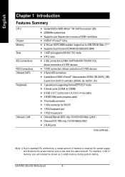
...1) Due to standard PC architecture, a certain amount of 2 FDD devices y 4 Serial ATA connectors y 2 ports from nVIDIA® nForce3TM Ultra controller (SATA0_SB, SATA1_SB); 2 ports from SiI3512 controller (SATA0_SII, SATA1_SII) y 1 parallel port supporting Normal/EPP/ECP mode y 2 Serial ports... memory during system startup. English Chapter 1 Introduction Features Summary CPU Chipset Memory Slots IDE Connections FDD Connections Onboard SATA Peripherals Onboard LAN y Socket 939 for AMD Althlon™ 64 / 64FX processor (K8)...less than the stated amount. GA-K8NS Ultra-939 Motherboard - 8 -
...1) Due to standard PC architecture, a certain amount of 2 FDD devices y 4 Serial ATA connectors y 2 ports from nVIDIA® nForce3TM Ultra controller (SATA0_SB, SATA1_SB); 2 ports from SiI3512 controller (SATA0_SII, SATA1_SII) y 1 parallel port supporting Normal/EPP/ECP mode y 2 Serial ports... memory during system startup. English Chapter 1 Introduction Features Summary CPU Chipset Memory Slots IDE Connections FDD Connections Onboard SATA Peripherals Onboard LAN y Socket 939 for AMD Althlon™ 64 / 64FX processor (K8)...less than the stated amount. GA-K8NS Ultra-939 Motherboard - 8 -
User Manual
Page 9
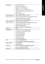
... (by optional Surround-Kit) y SPDIF In / Out y CD In / Game connector Onboard SATA RAID y Onboard nVIDIA® nForce3TM Ultra chipset (SATA0_SB, SATA1_SB) y Supports data striping (RAID 0) or mirroring (RAID 1) function y Supports data transfer rate of up 150 ... maximum of 2 SATA connections I/O Control y IT8712 Hardware Monitor y CPU / System / Power fan speed detection y CPU / System / Power fan failure warning y CPU temperature detection y CPU warning temperature y System voltage detection y CPU smart fan control y Thermal shutdown function BIOS y Use of licensed AWARD...
... (by optional Surround-Kit) y SPDIF In / Out y CD In / Game connector Onboard SATA RAID y Onboard nVIDIA® nForce3TM Ultra chipset (SATA0_SB, SATA1_SB) y Supports data striping (RAID 0) or mirroring (RAID 1) function y Supports data transfer rate of up 150 ... maximum of 2 SATA connections I/O Control y IT8712 Hardware Monitor y CPU / System / Power fan speed detection y CPU / System / Power fan failure warning y CPU temperature detection y CPU warning temperature y System voltage detection y CPU smart fan control y Thermal shutdown function BIOS y Use of licensed AWARD...
User Manual
Page 13
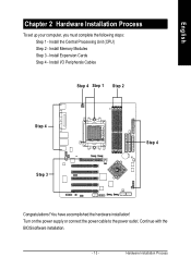
You have accomplished the hardware installation! Hardware Installation Process Install Memory Modules Step 3 - Turn on the power supply or connect the power cable to the power outlet. Install Expansion Cards Step 4 - Continue with the BIOS/software installation. - 13 - Install I/O Peripherals Cables Step 4 Step 1 Step 2 Step 4 Step 3 Step 4 Congratulations! Install the Central Processing Unit (CPU) Step 2 - English Chapter 2 Hardware Installation Process To set up your computer, you must complete the following steps: Step 1 -
You have accomplished the hardware installation! Hardware Installation Process Install Memory Modules Step 3 - Turn on the power supply or connect the power cable to the power outlet. Install Expansion Cards Step 4 - Continue with the BIOS/software installation. - 13 - Install I/O Peripherals Cables Step 4 Step 1 Step 2 Step 4 Step 3 Step 4 Congratulations! Install the Central Processing Unit (CPU) Step 2 - English Chapter 2 Hardware Installation Process To set up your computer, you must complete the following steps: Step 1 -
User Manual
Page 14
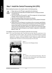
... processor to a triangle on the socket as shown in permanent irreparable damage. 3. Move the socket lever to inserting the processor. GA-K8NS Ultra-939 Motherboard - 14 - Please set the system bus frequency over the CPU's specification because these specific bus frequencies properly will result. 6. Whether your system can run the processor without the heatsink and...
... processor to a triangle on the socket as shown in permanent irreparable damage. 3. Move the socket lever to inserting the processor. GA-K8NS Ultra-939 Motherboard - 14 - Please set the system bus frequency over the CPU's specification because these specific bus frequencies properly will result. 6. Whether your system can run the processor without the heatsink and...
User Manual
Page 15
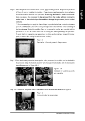
...contacts. ** We recommend you to the processor. Figure 6. Hardware Installation Process Phase change materials develop strong adhesive forces between your CPU and heatsink. (The CPU cooling fan might damage the processor. Align the heatsink assembly with the support frame mating with extreme caution.) Figure 3. Figure 4...(as shown in Figure 3) prior to the hardening of heatsink assembly with the cooling fan, and might stick to the CPU due to installing the heatsink. Alignment of the thermal paste. Removing the heatsink under such conditions can be removed from happening...
...contacts. ** We recommend you to the processor. Figure 6. Hardware Installation Process Phase change materials develop strong adhesive forces between your CPU and heatsink. (The CPU cooling fan might damage the processor. Align the heatsink assembly with the support frame mating with extreme caution.) Figure 3. Figure 4...(as shown in Figure 3) prior to the hardening of heatsink assembly with the cooling fan, and might stick to the CPU due to installing the heatsink. Alignment of the thermal paste. Removing the heatsink under such conditions can be removed from happening...
User Manual
Page 22
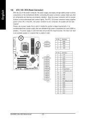
... and connect tightly. Align the power connector with its proper location on /off) 15 GND 16 GND 17 GND 18 -5V 19 VCC 20 VCC GA-K8NS Ultra-939 Motherboard - 22 - Caution! If the ATX_12V power connector is unable to start . Please use of the power connector, the power supply can withstand high power... consumption be used that does not provide the required power, the result can lead to the CPU. Before connecting the power connector, please make sure that is not connected, the system will not start . Pin No.
... and connect tightly. Align the power connector with its proper location on /off) 15 GND 16 GND 17 GND 18 -5V 19 VCC 20 VCC GA-K8NS Ultra-939 Motherboard - 22 - Caution! If the ATX_12V power connector is unable to start . Please use of the power connector, the power supply can withstand high power... consumption be used that does not provide the required power, the result can lead to the CPU. Before connecting the power connector, please make sure that is not connected, the system will not start . Pin No.
User Manual
Page 23
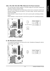
... positive connection and requires a +12V power voltage. The black connector wire is GND) Pin No. Please remember to connect the power to the CPU fan to prevent system overheating and failure. Hardware Installation Process Please remember to connect the power to the cooler to prevent... CPU overheating and failure. 1 CPU_FAN / PWR_FAN Pin No. 1 2 3 Definition GND +12V Sense 1 SYS_FAN 6) NB_FAN (Chip Fan Connector) If you installed wrong direction, the ...
... positive connection and requires a +12V power voltage. The black connector wire is GND) Pin No. Please remember to connect the power to the CPU fan to prevent system overheating and failure. Hardware Installation Process Please remember to connect the power to the cooler to prevent... CPU overheating and failure. 1 CPU_FAN / PWR_FAN Pin No. 1 2 3 Definition GND +12V Sense 1 SYS_FAN 6) NB_FAN (Chip Fan Connector) If you installed wrong direction, the ...

User Manual
Page 37
English z PC Health Status This setup page is control CPU's clock and frequency ratio. z Exit Without Saving Abandon all CMOS value changes and exit setup. - 37 - z Set Supervisor Password Change, set , or disable password. It ...
English z PC Health Status This setup page is control CPU's clock and frequency ratio. z Exit Without Saving Abandon all CMOS value changes and exit setup. - 37 - z Set Supervisor Password Change, set , or disable password. It ...
User Manual
Page 39
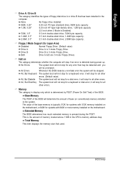
English Drive A / Drive B The category identifies the types of memory located above 1 MB in the CPU's memory address map. it will stop for all other errors. (Default value) All, But Diskette The system boot will not stop for a keyboard error; This ...
English Drive A / Drive B The category identifies the types of memory located above 1 MB in the CPU's memory address map. it will stop for all other errors. (Default value) All, But Diskette The system boot will not stop for a keyboard error; This ...

User Manual
Page 49
... function disable. (Default value) Enabled Fan warning function enable. BIOS Setup Enabled Enable CPU Smart Fan control function. (Default value) a. When the CPU temperature is between 50 and 60 degrees Celsius, CPU fan will run at 90oC / 194oF. Current CPU Temperature Detect CPU temperature automatically. CPU Warning Temperature Disabled Don't monitor current temperature. 60oC / 140oF Monitor...
... function disable. (Default value) Enabled Fan warning function enable. BIOS Setup Enabled Enable CPU Smart Fan control function. (Default value) a. When the CPU temperature is between 50 and 60 degrees Celsius, CPU fan will run at 90oC / 194oF. Current CPU Temperature Detect CPU temperature automatically. CPU Warning Temperature Disabled Don't monitor current temperature. 60oC / 140oF Monitor...

User Manual
Page 50
...AGP frequency as user selected. CPU Voltage Control Supports adjustable CPU Vcore from 0.800V to 1.700V by 0.025V step. (Default value: Normal) Normal CPU Vcore Display your system broken. AGP OverClock in MHz CPU Voltage Control Normal CPU Vcore AGP Voltage Control HT-...Previous Values F6: Fail-Save Defaults F7: Optimized Defaults Incorrect using these features may cause your CPU Vcore voltage. GA-K8NS Ultra-939 Motherboard - 50 - CPU OverClock in MHz 200MHz ~ 300MHz Increase CPU frequency as HT-Link required. (Default value) +0.1v Increase HT-Link voltage +0.1V. +0.2v...
...AGP frequency as user selected. CPU Voltage Control Supports adjustable CPU Vcore from 0.800V to 1.700V by 0.025V step. (Default value: Normal) Normal CPU Vcore Display your system broken. AGP OverClock in MHz CPU Voltage Control Normal CPU Vcore AGP Voltage Control HT-...Previous Values F6: Fail-Save Defaults F7: Optimized Defaults Incorrect using these features may cause your CPU Vcore voltage. GA-K8NS Ultra-939 Motherboard - 50 - CPU OverClock in MHz 200MHz ~ 300MHz Increase CPU frequency as HT-Link required. (Default value) +0.1v Increase HT-Link voltage +0.1V. +0.2v...
User Manual
Page 87
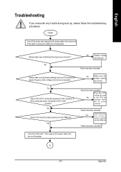
... power and unplug the AC power cable, then remove all jumper settings (such as CPU system bus speed, frequency ratio, voltage and etc) are not short ? ls CPU cooling fan power connected to CPU properly. Appendix English Troubleshooting If you encounter any trouble during boot up, please follow ...the VGA card. Please make sure motherboard & chassis are set properly. Then plug in the AC power connector. Plug the CPU cooling fan power No in the CPU fan connector. Failure has been excluded. Please make sure all of the add-on the system. No Yes Please isolate the...
... power and unplug the AC power cable, then remove all jumper settings (such as CPU system bus speed, frequency ratio, voltage and etc) are not short ? ls CPU cooling fan power connected to CPU properly. Appendix English Troubleshooting If you encounter any trouble during boot up, please follow ...the VGA card. Please make sure motherboard & chassis are set properly. Then plug in the AC power connector. Plug the CPU cooling fan power No in the CPU fan connector. Failure has been excluded. Please make sure all of the add-on the system. No Yes Please isolate the...
User Manual
Page 88
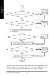
... been excluded. Yes Reinstall Windows OS, and reinstall add-on and CPU fan running? END If the above procedure unable to solve your problem, please contact with your question to the service mail via Gigabyte website technical support zone (http://www.gigabyte.com.tw). Turn off the system. English A Is memory LED on... working properly. No Perhaps your No keyboard or keyboard connector is defective. It is possible that your VGA card / VGA slot or monitor is defective. GA-K8NS Ultra-939 Motherboard - 88 -
... been excluded. Yes Reinstall Windows OS, and reinstall add-on and CPU fan running? END If the above procedure unable to solve your problem, please contact with your question to the service mail via Gigabyte website technical support zone (http://www.gigabyte.com.tw). Turn off the system. English A Is memory LED on... working properly. No Perhaps your No keyboard or keyboard connector is defective. It is possible that your VGA card / VGA slot or monitor is defective. GA-K8NS Ultra-939 Motherboard - 88 -
User Manual
Page 90
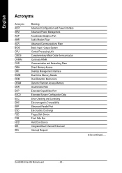
GA-K8NS Ultra-939 Motherboard - 90 - English Acronyms Acronyms ACPI APM AGP AMR ACR BIOS CPU CMOS CRIMM CNR DMA DMI DIMM DRM DRAM DDR ECP ESCD ECC EMC EPP ESD FDD FSB HDD IDE IRQ Meaning Advanced Configuration and Power ...
GA-K8NS Ultra-939 Motherboard - 90 - English Acronyms Acronyms ACPI APM AGP AMR ACR BIOS CPU CMOS CRIMM CNR DMA DMI DIMM DRM DRAM DDR ECP ESCD ECC EMC EPP ESD FDD FSB HDD IDE IRQ Meaning Advanced Configuration and Power ...


