Manual
Page 1
GA-H67MA-USB3-B3 LGA1155 socket motherboard for Intel® Core™ i7 processors/ Intel® Core™ i5 processors/Intel® Core™ i3 processors/ Intel® Pentium® processors/Intel® Celeron® processors User's Manual Rev. 1001 12ME-67MAB3B-1001R
GA-H67MA-USB3-B3 LGA1155 socket motherboard for Intel® Core™ i7 processors/ Intel® Core™ i5 processors/Intel® Core™ i3 processors/ Intel® Pentium® processors/Intel® Celeron® processors User's Manual Rev. 1001 12ME-67MAB3B-1001R
Manual
Page 3
... mentioned in this manual are legally registered to assist in this : "REV: X.X." Check your motherboard looks like this manual may be made by GIGABYTE without GIGABYTE's prior written permission. Copyright © 2011 GIGA-BYTE TECHNOLOGY CO., LTD. Documentation Classifications In ... Example: For product-related information, check on our website at: http://www.gigabyte.com Identifying Your Motherboard Revision The revision number on your motherboard revision before updating motherboard BIOS, drivers, or when looking for technical information. Changes to the specifications ...
... mentioned in this manual are legally registered to assist in this : "REV: X.X." Check your motherboard looks like this manual may be made by GIGABYTE without GIGABYTE's prior written permission. Copyright © 2011 GIGA-BYTE TECHNOLOGY CO., LTD. Documentation Classifications In ... Example: For product-related information, check on our website at: http://www.gigabyte.com Identifying Your Motherboard Revision The revision number on your motherboard revision before updating motherboard BIOS, drivers, or when looking for technical information. Changes to the specifications ...
Manual
Page 4
Table of Contents Box Contents...6 Optional Items...6 GA-H67MA-USB3-B3 Motherboard Layout 7 GA-H67MA-USB3-B3 Motherboard Block Diagram 8 Chapter 1 Hardware Installation 9 1-1 Installation Precautions 9 1-2 Product Specifications 10 1-3 Installing the CPU and CPU Cooler 13 1-3-1 Installing the CPU 13 1-3-2 Installing the CPU Cooler ...
Table of Contents Box Contents...6 Optional Items...6 GA-H67MA-USB3-B3 Motherboard Layout 7 GA-H67MA-USB3-B3 Motherboard Block Diagram 8 Chapter 1 Hardware Installation 9 1-1 Installation Precautions 9 1-2 Product Specifications 10 1-3 Installing the CPU and CPU Cooler 13 1-3-1 Installing the CPU 13 1-3-2 Installing the CPU Cooler ...
Manual
Page 6
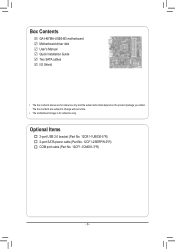
Optional Items 2-port USB 2.0 bracket (Part No. 12CR1-1UB030-5*R) 2-port SATA power cable (Part No. 12CF1-2SERPW-0*R) COM port cable (Part No. 12CF1-1CM001-3*R) - 6 - Box Contents GA-H67MA-USB3-B3 motherboard Motherboard driver disk User's Manual Quick Installation Guide Two SATA cables I/O Shield • The box contents above are subject to change without notice. • The motherboard image is for reference only and the actual items shall depend on the product package you obtain. The box contents are for reference only.
Optional Items 2-port USB 2.0 bracket (Part No. 12CR1-1UB030-5*R) 2-port SATA power cable (Part No. 12CF1-2SERPW-0*R) COM port cable (Part No. 12CF1-1CM001-3*R) - 6 - Box Contents GA-H67MA-USB3-B3 motherboard Motherboard driver disk User's Manual Quick Installation Guide Two SATA cables I/O Shield • The box contents above are subject to change without notice. • The motherboard image is for reference only and the actual items shall depend on the product package you obtain. The box contents are for reference only.
Manual
Page 7
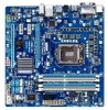
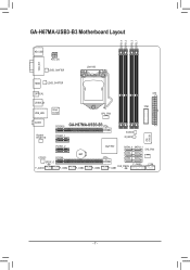
GA-H67MA-USB3-B3 Motherboard Layout DDR3_4 DDR3_2 DDR3_3 DDR3_1 KB_USB ATX_12V VGA_DVI LEVEL SHIFTER LGA1155 HDMI LEVEL SHIFTER OPTICAL ATX USB30_20 USB_LAN Etron EJ168 TPM CPU_FAN AUDIO Realtek RTL8111E PCIEX16 GA-H67MA-USB3-B3 PCIEX1_1 B_BIOS M_BIOS iTE IT8728 PCIEX1_2 CODEC PCIEX4 SPDIF_O F_AUDIO F_USB4 BAT F_USB3 F_USB2 Intel® H67 SATA3_0 SATA3_1 SYS_FAN SATA2_2 SATA2_3 SATA2_4 SATA2_5 F_PANEL COM CLR_CMOS F_USB1 - 7 -
GA-H67MA-USB3-B3 Motherboard Layout DDR3_4 DDR3_2 DDR3_3 DDR3_1 KB_USB ATX_12V VGA_DVI LEVEL SHIFTER LGA1155 HDMI LEVEL SHIFTER OPTICAL ATX USB30_20 USB_LAN Etron EJ168 TPM CPU_FAN AUDIO Realtek RTL8111E PCIEX16 GA-H67MA-USB3-B3 PCIEX1_1 B_BIOS M_BIOS iTE IT8728 PCIEX1_2 CODEC PCIEX4 SPDIF_O F_AUDIO F_USB4 BAT F_USB3 F_USB2 Intel® H67 SATA3_0 SATA3_1 SYS_FAN SATA2_2 SATA2_3 SATA2_4 SATA2_5 F_PANEL COM CLR_CMOS F_USB1 - 7 -
Manual
Page 8
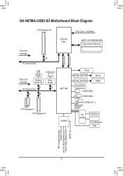
GA-H67MA-USB3-B3 Motherboard Block Diagram 1 PCI Express x16 CPU CLK+/- (100 MHz) LGA1155 CPU DDR3 1333/1066/800 MHz Dual Channel Memory DMI Interface FDI Interface PCIe CLK (...
GA-H67MA-USB3-B3 Motherboard Block Diagram 1 PCI Express x16 CPU CLK+/- (100 MHz) LGA1155 CPU DDR3 1333/1066/800 MHz Dual Channel Memory DMI Interface FDI Interface PCIe CLK (...
Manual
Page 9
... •• Before using the product, please verify that all cables and power connectors of your dealer. ponents such as a motherboard, CPU or memory. Prior to installation, carefully read the user's manual and follow these procedures: •• Prior to installation,... as a result of the product, please consult a certified computer technician. - 9 - Chapter 1 Hardware Installation 1-1 Installation Precautions The motherboard contains numerous delicate electronic circuits and components which can lead to damage to system components as well as physical harm to the user. &#...
... •• Before using the product, please verify that all cables and power connectors of your dealer. ponents such as a motherboard, CPU or memory. Prior to installation, carefully read the user's manual and follow these procedures: •• Prior to installation,... as a result of the product, please consult a certified computer technician. - 9 - Chapter 1 Hardware Installation 1-1 Installation Precautions The motherboard contains numerous delicate electronic circuits and components which can lead to damage to system components as well as physical harm to the user. &#...
Manual
Page 12
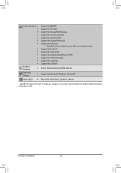
...ŠŠ Support for Xpress Install ŠŠ Support for Xpress Recovery2 ŠŠ Support for EasyTune * Available functions in EasyTune may differ by motherboard model. ŠŠ Support for Smart 6™ ŠŠ Support for Auto Green ŠŠ Support for eXtreme Hard Drive (X.H.D) ŠŠ... ŠŠ Support for Microsoft® Windows 7/Vista/XP Form Factor ŠŠ Micro ATX Form Factor; 24.4cm x 24.4cm * GIGABYTE reserves the right to make any changes to the product specifications and product-related information without prior notice.
...ŠŠ Support for Xpress Install ŠŠ Support for Xpress Recovery2 ŠŠ Support for EasyTune * Available functions in EasyTune may differ by motherboard model. ŠŠ Support for Smart 6™ ŠŠ Support for Auto Green ŠŠ Support for eXtreme Hard Drive (X.H.D) ŠŠ... ŠŠ Support for Microsoft® Windows 7/Vista/XP Form Factor ŠŠ Micro ATX Form Factor; 24.4cm x 24.4cm * GIGABYTE reserves the right to make any changes to the product specifications and product-related information without prior notice.
Manual
Page 13
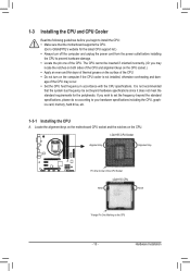
...the latest CPU support list.) •• Always turn on the computer if the CPU cooler is not recommended that the motherboard supports the CPU. (Go to GIGABYTE's website for the peripherals. age of the CPU may locate the notches on both sides of the CPU and alignment keys...CPU. If you may occur. •• Set the CPU host frequency in accordance with the CPU specifications. Locate the alignment keys on the motherboard CPU socket and the notches on the CPU - 13 - Hardware Installation It is not installed, otherwise overheating and dam- 1-3 Installing the CPU and...
...the latest CPU support list.) •• Always turn on the computer if the CPU cooler is not recommended that the motherboard supports the CPU. (Go to GIGABYTE's website for the peripherals. age of the CPU may locate the notches on both sides of the CPU and alignment keys...CPU. If you may occur. •• Set the CPU host frequency in accordance with the CPU specifications. Locate the alignment keys on the motherboard CPU socket and the notches on the CPU - 13 - Hardware Installation It is not installed, otherwise overheating and dam- 1-3 Installing the CPU and...

Manual
Page 14
... with your thumb to lift up the front edge (next to lightly replace the load plate. Step 5: Push the CPU socket lever back into the motherboard CPU socket.
... with your thumb to lift up the front edge (next to lightly replace the load plate. Step 5: Push the CPU socket lever back into the motherboard CPU socket.

Manual
Page 15
... CPU. Check that the Male and Female push pins are joined closely. (Refer to your CPU cooler installation manual for instructions on the motherboard. Hardware Installation Step 2: Before installing the cooler, note the direction of the arrow sign on the male push pin. (Turning the push...header (CPU_FAN) on the push pins diagonally. Step 4: You should hear a "click" when pushing down on the motherboard. Step 6: Finally, attach the power connector of the motherboard. Use extreme care when removing the CPU cooler because the thermal grease/tape between the CPU cooler and CPU may ...
... CPU. Check that the Male and Female push pins are joined closely. (Refer to your CPU cooler installation manual for instructions on the motherboard. Hardware Installation Step 2: Before installing the cooler, note the direction of the arrow sign on the male push pin. (Turning the push...header (CPU_FAN) on the push pins diagonally. Step 4: You should hear a "click" when pushing down on the motherboard. Step 6: Finally, attach the power connector of the motherboard. Use extreme care when removing the CPU cooler because the thermal grease/tape between the CPU cooler and CPU may ...
Manual
Page 16
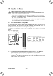
..., "- -"=No Memory) DDR3_4 DDR3_2 DDR3_3 DDR3_1 Due to insert the memory, switch the direction. 1-4-1 Dual Channel Memory Configuration This motherboard provides four DDR3 memory sockets and supports Dual Channel Technology. After the memory is recommended that memory of the same capacity, brand, ...four memory modules, it is installed, the BIOS will double the original memory bandwidth. A memory module can be used . (Go to GIGABYTE's website for optimum performance. Hardware Installation - 16 - If you begin to prevent hardware damage. •• Memory modules have a ...
..., "- -"=No Memory) DDR3_4 DDR3_2 DDR3_3 DDR3_1 Due to insert the memory, switch the direction. 1-4-1 Dual Channel Memory Configuration This motherboard provides four DDR3 memory sockets and supports Dual Channel Technology. After the memory is recommended that memory of the same capacity, brand, ...four memory modules, it is installed, the BIOS will double the original memory bandwidth. A memory module can be used . (Go to GIGABYTE's website for optimum performance. Hardware Installation - 16 - If you begin to prevent hardware damage. •• Memory modules have a ...
Manual
Page 17
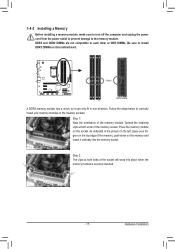
... below to correctly install your fingers on the top edge of the socket will snap into the memory socket. Place the memory module on this motherboard. Step 1: Note the orientation of the memory socket. DDR3 and DDR2 DIMMs are not compatible to each other or DDR DIMMs. Be sure to the...
... below to correctly install your fingers on the top edge of the socket will snap into the memory socket. Place the memory module on this motherboard. Step 1: Note the orientation of the memory socket. DDR3 and DDR2 DIMMs are not compatible to each other or DDR DIMMs. Be sure to the...
Manual
Page 18
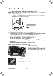
... card with the slot, and press down on the top edge of the PCI Express slot to install an expansion card: • Make sure the motherboard supports the expansion card.
... card with the slot, and press down on the top edge of the PCI Express slot to install an expansion card: • Make sure the motherboard supports the expansion card.
Manual
Page 20
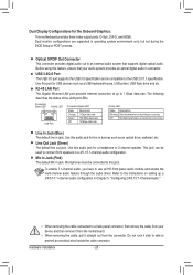
... transmission or receiving is occurring Off No data transmission or receiving is compatible to 1 Gbps data rate. Do not rock it straight out from the motherboard. •• When removing the cable, pull it side to side to this audio jack for the Onboard Graphics: This... motherboard provides three video output ports: D-Sub, DVI-D, and HDMI. Hardware Installation - 20 - Mic In Jack (Pink) The default Mic in jack. Dual Display Configurations for a ...
... transmission or receiving is occurring Off No data transmission or receiving is compatible to 1 Gbps data rate. Do not rock it straight out from the motherboard. •• When removing the cable, pull it side to side to this audio jack for the Onboard Graphics: This... motherboard provides three video output ports: D-Sub, DVI-D, and HDMI. Hardware Installation - 20 - Mic In Jack (Pink) The default Mic in jack. Dual Display Configurations for a ...
Manual
Page 21
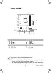
... 3) CPU_FAN 4) SYS_FAN 5) BAT 6) SATA3_0/1 7) SATA2_2/3/4/5 8) F_PANEL 9) F_AUDIO 10) SPDIF_O 11) F_USB1/2/3/4 12) COM 13) TPM 14) CLR_CMOS Read the following guidelines before turning on the motherboard. - 21 - Hardware Installation
... 3) CPU_FAN 4) SYS_FAN 5) BAT 6) SATA3_0/1 7) SATA2_2/3/4/5 8) F_PANEL 9) F_AUDIO 10) SPDIF_O 11) F_USB1/2/3/4 12) COM 13) TPM 14) CLR_CMOS Read the following guidelines before turning on the motherboard. - 21 - Hardware Installation
Manual
Page 22
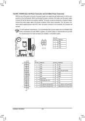
... the power supply cable to the CPU. The power connector possesses a foolproof design. If a power supply is turned off and all the components on the motherboard. To meet expansion requirements, it is not connected, the computer will not start. 1/2) ATX_12V/ATX (2x2 12V Power Connector and 2x12 Main Power Connector) With...
... the power supply cable to the CPU. The power connector possesses a foolproof design. If a power supply is turned off and all the components on the motherboard. To meet expansion requirements, it is not connected, the computer will not start. 1/2) ATX_12V/ATX (2x2 12V Power Connector and 2x12 Main Power Connector) With...

Manual
Page 23
...restart your computer. •• Always turn off your CPU and system from the battery holder and wait for one . The motherboard supports CPU fan speed control, which requires the use a metal object like a screwdriver to touch the positive and negative terminals of ... power cord before replacing the battery. •• Replace the battery with local environmental regulations. - 23 - 3/4) CPU_FAN/SYS_FAN (Fan Headers) The motherboard has a 4-pin CPU fan header (CPU_FAN), a 4-pin system fan header (SYS_FAN). Most fan headers possess a foolproof insertion design. For optimum heat...
...restart your computer. •• Always turn off your CPU and system from the battery holder and wait for one . The motherboard supports CPU fan speed control, which requires the use a metal object like a screwdriver to touch the positive and negative terminals of ... power cord before replacing the battery. •• Replace the battery with local environmental regulations. - 23 - 3/4) CPU_FAN/SYS_FAN (Fan Headers) The motherboard has a 4-pin CPU fan header (CPU_FAN), a 4-pin system fan header (SYS_FAN). Most fan headers possess a foolproof insertion design. For optimum heat...
Manual
Page 26
...Audio signals will make the device unable to certain expansion cards like graphics cards and sound cards. Pin No. If your motherboard to work or even damage it. Definition 1 1 SPDIFO 2 GND Hardware Installation - 26 - For information about connecting the... S/PDIF digital audio cable, carefully read the manual for digital audio output from your motherboard to Chapter 5, "Configuring 2/4/5.1/7.1-Channel Audio." •• Some chassis provide a front panel audio module that has different wire assignments...
...Audio signals will make the device unable to certain expansion cards like graphics cards and sound cards. Pin No. If your motherboard to work or even damage it. Definition 1 1 SPDIFO 2 GND Hardware Installation - 26 - For information about connecting the... S/PDIF digital audio cable, carefully read the manual for digital audio output from your motherboard to Chapter 5, "Configuring 2/4/5.1/7.1-Channel Audio." •• Some chassis provide a front panel audio module that has different wire assignments...
Manual
Page 28
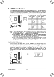
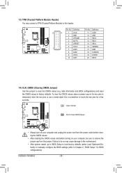
... a metal object like a screwdriver to Chapter 2, "BIOS Setup," for a few seconds. TPM w/housing 13) TPM (Trusted Platform Module Header) You may cause damage to the motherboard. •• After system restart, go to BIOS Setup to load factory defaults (select Load Optimized Defaults) or manually configure the BIOS settings (refer to...
... a metal object like a screwdriver to Chapter 2, "BIOS Setup," for a few seconds. TPM w/housing 13) TPM (Trusted Platform Module Header) You may cause damage to the motherboard. •• After system restart, go to BIOS Setup to load factory defaults (select Load Optimized Defaults) or manually configure the BIOS settings (refer to...


