
Manual
Page 1
GA-H67MA-UD2H-B3 LGA1155 socket motherboard for Intel® Core™ i7 processors/ Intel® Core™ i5 processors/Intel® Core™ i3 processors/ Intel® Pentium® processors/Intel® Celeron® processors User's Manual Rev. 1101 12ME-H67U2HB-1101R
GA-H67MA-UD2H-B3 LGA1155 socket motherboard for Intel® Core™ i7 processors/ Intel® Core™ i5 processors/Intel® Core™ i3 processors/ Intel® Pentium® processors/Intel® Celeron® processors User's Manual Rev. 1101 12ME-H67U2HB-1101R
Manual
Page 3
The trademarks mentioned in the use of this product, GIGABYTE provides the following types of documentations: For quick set-up of the motherboard is the property of this manual may be reproduced, copied, translated, transmitted, or published in this ... Check your motherboard looks like this manual may be made by GIGABYTE without GIGABYTE's prior written permission. For product-related information, check on our website at: http://www.gigabyte.com Identifying Your Motherboard Revision The revision number on your motherboard revision before updating motherboard BIOS, drivers...
The trademarks mentioned in the use of this product, GIGABYTE provides the following types of documentations: For quick set-up of the motherboard is the property of this manual may be reproduced, copied, translated, transmitted, or published in this ... Check your motherboard looks like this manual may be made by GIGABYTE without GIGABYTE's prior written permission. For product-related information, check on our website at: http://www.gigabyte.com Identifying Your Motherboard Revision The revision number on your motherboard revision before updating motherboard BIOS, drivers...

Manual
Page 4
Table of Contents Box Contents...6 Optional Items...6 GA-H67MA-UD2H-B3 Motherboard Layout 7 GA-H67MA-UD2H-B3 Motherboard Block Diagram 8 Chapter 1 Hardware Installation 9 1-1 Installation Precautions 9 1-2 Product Specifications 10 1-3 Installing the CPU and CPU Cooler 13 1-3-1 Installing the CPU 13 1-3-2 Installing the CPU Cooler ...
Table of Contents Box Contents...6 Optional Items...6 GA-H67MA-UD2H-B3 Motherboard Layout 7 GA-H67MA-UD2H-B3 Motherboard Block Diagram 8 Chapter 1 Hardware Installation 9 1-1 Installation Precautions 9 1-2 Product Specifications 10 1-3 Installing the CPU and CPU Cooler 13 1-3-1 Installing the CPU 13 1-3-2 Installing the CPU Cooler ...

Manual
Page 6
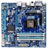
Optional Items 2-port USB 2.0 bracket (Part No. 12CR1-1UB030-5*R) 2-port SATA power cable (Part No. 12CF1-2SERPW-0*R) COM port cable (Part No. 12CF1-1CM001-3*R) - 6 - The box contents are for reference only. Box Contents GA-H67MA-UD2H-B3 motherboard Motherboard driver disk User's Manual Quick Installation Guide Four SATA cables I/O Shield • The box contents above are subject to change without notice. • The motherboard image is for reference only and the actual items shall depend on the product package you obtain.
Optional Items 2-port USB 2.0 bracket (Part No. 12CR1-1UB030-5*R) 2-port SATA power cable (Part No. 12CF1-2SERPW-0*R) COM port cable (Part No. 12CF1-1CM001-3*R) - 6 - The box contents are for reference only. Box Contents GA-H67MA-UD2H-B3 motherboard Motherboard driver disk User's Manual Quick Installation Guide Four SATA cables I/O Shield • The box contents above are subject to change without notice. • The motherboard image is for reference only and the actual items shall depend on the product package you obtain.
Manual
Page 7
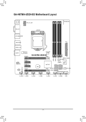
GA-H67MA-UD2H-B3 Motherboard Layout KB_USB ATX_12V_2X4 PHASE LED VGA_DVI LGA1155 DP_HDMI_SPDIF USB_ESATA ATX USB30_LAN AUDIO Realtek RTL8111E CODEC Renesas D720200 PCIEX16 PCIEX1_1 PCIEX1_2 PCIEX4 CPU_FAN DDR3_4 GA-H67MA-UD2H-B3 CLR_CMOS B_BIOS DDR3_1 DDR3_2 DDR3_3 iTE IT8728 M_BIOS Intel® H67 SATA3_0 SATA3_1 BAT SATA2_2 SATA2_4 SATA2_3 SYS_FAN SPDIF_O F_AUDIO F_USB5 F_USB4 F_USB3 F_USB2 F_USB1 F_PANEL COM - 7 -
GA-H67MA-UD2H-B3 Motherboard Layout KB_USB ATX_12V_2X4 PHASE LED VGA_DVI LGA1155 DP_HDMI_SPDIF USB_ESATA ATX USB30_LAN AUDIO Realtek RTL8111E CODEC Renesas D720200 PCIEX16 PCIEX1_1 PCIEX1_2 PCIEX4 CPU_FAN DDR3_4 GA-H67MA-UD2H-B3 CLR_CMOS B_BIOS DDR3_1 DDR3_2 DDR3_3 iTE IT8728 M_BIOS Intel® H67 SATA3_0 SATA3_1 BAT SATA2_2 SATA2_4 SATA2_3 SYS_FAN SPDIF_O F_AUDIO F_USB5 F_USB4 F_USB3 F_USB2 F_USB1 F_PANEL COM - 7 -

Manual
Page 8
GA-H67MA-UD2H-B3 Motherboard Block Diagram 1 PCI Express x16 LGA1155 CPU CPU CLK+/- (100 MHz) DDR3 1333/1066/800 MHz Dual Channel Memory PCIe CLK (100 MHz) x16 PCI ...
GA-H67MA-UD2H-B3 Motherboard Block Diagram 1 PCI Express x16 LGA1155 CPU CPU CLK+/- (100 MHz) DDR3 1333/1066/800 MHz Dual Channel Memory PCIe CLK (100 MHz) x16 PCI ...

Manual
Page 9
...8226; It is best to wear an electrostatic discharge (ESD) wrist strap when handling electronic com- Chapter 1 Hardware Installation 1-1 Installation Precautions The motherboard contains numerous delicate electronic circuits and components which can lead to damage to system components as well as physical harm to the user. •...an ESD wrist strap, keep your hands dry and first touch a metal object to eliminate static electricity. • Prior to installing the motherboard, please have it on top of an antistatic pad or within the computer casing. • Do not place the computer system on ...
...8226; It is best to wear an electrostatic discharge (ESD) wrist strap when handling electronic com- Chapter 1 Hardware Installation 1-1 Installation Precautions The motherboard contains numerous delicate electronic circuits and components which can lead to damage to system components as well as physical harm to the user. •...an ESD wrist strap, keep your hands dry and first touch a metal object to eliminate static electricity. • Prior to installing the motherboard, please have it on top of an antistatic pad or within the computer casing. • Do not place the computer system on ...
Manual
Page 12
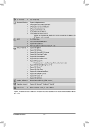
... for Cloud OC Support for Q-Share Bundled Software w Norton Internet Security (OEM version) Operating System w Support for EasyTune * Available functions in EasyTune may differ by motherboard model. Hardware Installation - 12 -
... for Cloud OC Support for Q-Share Bundled Software w Norton Internet Security (OEM version) Operating System w Support for EasyTune * Available functions in EasyTune may differ by motherboard model. Hardware Installation - 12 -
Manual
Page 13
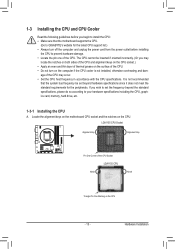
...on the surface of the CPU. • Do not turn on the computer if the CPU cooler is not recommended that the motherboard supports the CPU. (Go to GIGABYTE's website for the latest CPU support list.) • Always turn off the computer and unplug the power cord from the power ...drive, etc. 1-3-1 Installing the CPU A. LGA1155 CPU Socket Alignment Key Alignment Key Pin One Corner of the CPU. Locate the alignment keys on the motherboard CPU socket and the notches on the CPU - 13 - 1-3 Installing the CPU and CPU Cooler Read the following guidelines before installing the CPU to prevent...
...on the surface of the CPU. • Do not turn on the computer if the CPU cooler is not recommended that the motherboard supports the CPU. (Go to GIGABYTE's website for the latest CPU support list.) • Always turn off the computer and unplug the power cord from the power ...drive, etc. 1-3-1 Installing the CPU A. LGA1155 CPU Socket Alignment Key Alignment Key Pin One Corner of the CPU. Locate the alignment keys on the motherboard CPU socket and the notches on the CPU - 13 - 1-3 Installing the CPU and CPU Cooler Read the following guidelines before installing the CPU to prevent...
Manual
Page 14
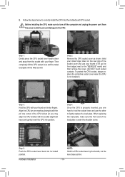
... position. Hardware Installation - 14 - Hold your index finger down and away from the power outlet to prevent damage to correctly install the CPU into the motherboard CPU socket. Align the CPU pin one marking (triangle) with the pin one hand to hold the socket lever and use one corner of the...
... position. Hardware Installation - 14 - Hold your index finger down and away from the power outlet to prevent damage to correctly install the CPU into the motherboard CPU socket. Align the CPU pin one marking (triangle) with the pin one hand to hold the socket lever and use one corner of the...
Manual
Page 15
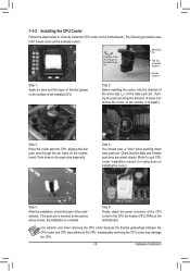
... 2: Before installing the cooler, note the direction of the arrow sign on the male push pin. (Turning the push pin along the direction of the motherboard. Check that the Male and Female push pins are joined closely. (Refer to your CPU cooler installation manual for instructions on the... motherboard. Use extreme care when removing the CPU cooler because the thermal grease/tape between the CPU cooler and CPU may damage the CPU. - 15 - Step 6: ...
... 2: Before installing the cooler, note the direction of the arrow sign on the male push pin. (Turning the push pin along the direction of the motherboard. Check that the Male and Female push pins are joined closely. (Refer to your CPU cooler installation manual for instructions on the... motherboard. Use extreme care when removing the CPU cooler because the thermal grease/tape between the CPU cooler and CPU may damage the CPU. - 15 - Step 6: ...
Manual
Page 16
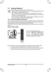
...foolproof design. DS/SS DS/SS DDR3_3 DS/SS - Hardware Installation - 16 - Dual Channel Memory Configuration This motherboard provides four DDR3 memory sockets and supports Dual Channel Technology. DS/SS DDR3_4 - Dual Channel mode cannot be ... DDR3_2 DDR3_3 DDR3_4 Due to insert the memory, switch the direction. After the memory is recommended that the motherboard supports the memory. Enabling Dual Channel memory mode will automatically detect the specifications and capacity of the memory....brand, speed, and chips be used . (Go to GIGABYTE's website for optimum performance.
...foolproof design. DS/SS DS/SS DDR3_3 DS/SS - Hardware Installation - 16 - Dual Channel Memory Configuration This motherboard provides four DDR3 memory sockets and supports Dual Channel Technology. DS/SS DDR3_4 - Dual Channel mode cannot be ... DDR3_2 DDR3_3 DDR3_4 Due to insert the memory, switch the direction. After the memory is recommended that the motherboard supports the memory. Enabling Dual Channel memory mode will automatically detect the specifications and capacity of the memory....brand, speed, and chips be used . (Go to GIGABYTE's website for optimum performance.
Manual
Page 17
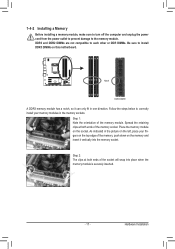
..., make sure to turn off the computer and unplug the power cord from the power outlet to prevent damage to install DDR3 DIMMs on this motherboard. DDR3 and DDR2 DIMMs are not compatible to each other or DDR DIMMs. Be sure to the memory module. Follow the steps below to correctly...
..., make sure to turn off the computer and unplug the power cord from the power outlet to prevent damage to install DDR3 DIMMs on this motherboard. DDR3 and DDR2 DIMMs are not compatible to each other or DDR DIMMs. Be sure to the memory module. Follow the steps below to correctly...

Manual
Page 18
... chassis back panel. 2. 1-5 Installing an Expansion Card Read the following guidelines before installing an expansion card to install an expansion card: • Make sure the motherboard supports the expansion card. Example: Installing and Removing a PCI Express Graphics Card: • Installing a Graphics Card: Gently push down on the card are completely inserted...
... chassis back panel. 2. 1-5 Installing an Expansion Card Read the following guidelines before installing an expansion card to install an expansion card: • Make sure the motherboard supports the expansion card. Example: Installing and Removing a PCI Express Graphics Card: • Installing a Graphics Card: Gently push down on the card are completely inserted...

Manual
Page 20
... the USB 3.0 specification and is compatible with SATA 1.5Gb/s standard. After installing the DisplayPort device, make sure the default device for the Onboard Graphics: This motherboard provides three video output ports: D-Sub, DVI-D, and HDMI. The following describes the states of the new generation interface technologies that supports DisplayPort to the...
... the USB 3.0 specification and is compatible with SATA 1.5Gb/s standard. After installing the DisplayPort device, make sure the default device for the Onboard Graphics: This motherboard provides three video output ports: D-Sub, DVI-D, and HDMI. The following describes the states of the new generation interface technologies that supports DisplayPort to the...

Manual
Page 21
... this audio jack for a headphone or 2-channel speaker. Line Out Jack (Green) The default line out jack. Do not rock it straight out from the motherboard. • When removing the cable, pull it side to side to connect rear speakers in a 5.1/7.1-channel audio configuration. In addition to the default speakers settings...
... this audio jack for a headphone or 2-channel speaker. Line Out Jack (Green) The default line out jack. Do not rock it straight out from the motherboard. • When removing the cable, pull it side to side to connect rear speakers in a 5.1/7.1-channel audio configuration. In addition to the default speakers settings...

Manual
Page 22
... 3) CPU_FAN 4) SYS_FAN 5) BAT 6) SATA3_0/1 7) SATA2_2/3/4 8) F_PANEL 9) F_AUDIO 10) SPDIF_O 11) F_USB1/2/3/4/5 12) COM 13) CLR_CMOS 14) PHASE_LED Read the following guidelines before turning on the motherboard. Hardware Installation - 22 - Unplug the power cord from the power outlet to prevent damage to the devices. • After installing the device and before connecting...
... 3) CPU_FAN 4) SYS_FAN 5) BAT 6) SATA3_0/1 7) SATA2_2/3/4 8) F_PANEL 9) F_AUDIO 10) SPDIF_O 11) F_USB1/2/3/4/5 12) COM 13) CLR_CMOS 14) PHASE_LED Read the following guidelines before turning on the motherboard. Hardware Installation - 22 - Unplug the power cord from the power outlet to prevent damage to the devices. • After installing the device and before connecting...

Manual
Page 23
If the 12V power connector is turned off and all the components on the motherboard. To meet expansion requirements, it is used (500W or greater). Definition 1 GND (Only for 2x4-pin 12V) 2 GND (Only for 2x4-pin 12V) 3 GND 4 GND 5 +...
If the 12V power connector is turned off and all the components on the motherboard. To meet expansion requirements, it is used (500W or greater). Definition 1 GND (Only for 2x4-pin 12V) 2 GND (Only for 2x4-pin 12V) 3 GND 4 GND 5 +...

Manual
Page 24
... 1 GND 2 +12V / Speed Control 3 Sense 4 Speed Control 1 SYS_FAN SYS_FAN: Pin No. Gently remove the battery from overheating. The motherboard supports CPU fan speed control, which requires the use a metal object like a screwdriver to keep the values (such as BIOS configurations, date, and... environmental regulations. For optimum heat dissipation, it in the CMOS when the computer is the ground wire). 3/4) CPU_FAN/SYS_FAN (Fan Headers) The motherboard has a 4-pin CPU fan header (CPU_FAN) and a 4-pin system fan headers (SYS_FAN). Most fan headers possess a foolproof insertion design. ...
... 1 GND 2 +12V / Speed Control 3 Sense 4 Speed Control 1 SYS_FAN SYS_FAN: Pin No. Gently remove the battery from overheating. The motherboard supports CPU fan speed control, which requires the use a metal object like a screwdriver to keep the values (such as BIOS configurations, date, and... environmental regulations. For optimum heat dissipation, it in the CMOS when the computer is the ground wire). 3/4) CPU_FAN/SYS_FAN (Fan Headers) The motherboard has a 4-pin CPU fan header (CPU_FAN) and a 4-pin system fan headers (SYS_FAN). Most fan headers possess a foolproof insertion design. ...

Manual
Page 27
Make sure the wire assignments of the motherboard header. Incorrect connection between the module connector and the motherboard header will be present on each wire instead of the front and back panel audio connections simultane- If your chassis provides an AC'97 ...or even damage it. For information about connecting the S/PDIF digital audio cable, carefully read the manual for your motherboard to use a S/PDIF digital audio cable for digital audio output from your motherboard to your chassis front panel audio module to the graphics card and have digital audio output from the HDMI...
Make sure the wire assignments of the motherboard header. Incorrect connection between the module connector and the motherboard header will be present on each wire instead of the front and back panel audio connections simultane- If your chassis provides an AC'97 ...or even damage it. For information about connecting the S/PDIF digital audio cable, carefully read the manual for your motherboard to use a S/PDIF digital audio cable for digital audio output from your motherboard to your chassis front panel audio module to the graphics card and have digital audio output from the HDMI...


