
Manual
Page 1
GA-H55M-UD2H/ GA-H55M-US2H LGA1156 socket motherboard for Intel® Core™ i7 processor family/ Intel® Core™ i5 processor family/ Intel® Core™ i3 processor family User's Manual Rev. 1002 12ME-H55MUD2-1002R
GA-H55M-UD2H/ GA-H55M-US2H LGA1156 socket motherboard for Intel® Core™ i7 processor family/ Intel® Core™ i5 processor family/ Intel® Core™ i3 processor family User's Manual Rev. 1002 12ME-H55MUD2-1002R

Manual
Page 2
Motherboard GA-H55M-UD2H/GA-H55M-US2H Nov. 14, 2009 Motherboard GA-H55M-UD2H/ GA-H55M-US2H Nov. 14, 2009
Motherboard GA-H55M-UD2H/GA-H55M-US2H Nov. 14, 2009 Motherboard GA-H55M-UD2H/ GA-H55M-US2H Nov. 14, 2009

Manual
Page 3
...on how to assist in this manual may be made by copyright laws and is 1.0. The trademarks mentioned in the use GIGABYTE's unique features, read or download the information on/from the Support&Downloads\Motherboard\Technology Guide page on your motherboard revision before...the product, read the User's Manual. Check your motherboard looks like this manual is protected by GIGABYTE without GIGABYTE's prior written permission. No part of this product, GIGABYTE provides the following types of documentations: For quick set-up of this manual may be reproduced, copied...
...on how to assist in this manual may be made by copyright laws and is 1.0. The trademarks mentioned in the use GIGABYTE's unique features, read or download the information on/from the Support&Downloads\Motherboard\Technology Guide page on your motherboard revision before...the product, read the User's Manual. Check your motherboard looks like this manual is protected by GIGABYTE without GIGABYTE's prior written permission. No part of this product, GIGABYTE provides the following types of documentations: For quick set-up of this manual may be reproduced, copied...

Manual
Page 4
Table of Contents Box Contents...6 Optional Items...6 GA-H55M-UD2H/GA-H55M-US2H Motherboard Layout 7 Block Diagram...8 Chapter 1 Hardware Installation 9 1-1 Installation Precautions 9 1-2 Product Specifications 10 1-3 Installing the CPU and CPU Cooler 13 1-3-1 Installing the CPU 13 1-3-2 Installing ...
Table of Contents Box Contents...6 Optional Items...6 GA-H55M-UD2H/GA-H55M-US2H Motherboard Layout 7 Block Diagram...8 Chapter 1 Hardware Installation 9 1-1 Installation Precautions 9 1-2 Product Specifications 10 1-3 Installing the CPU and CPU Cooler 13 1-3-1 Installing the CPU 13 1-3-2 Installing ...

Manual
Page 5
Chapter 3 Drivers Installation 61 3-1 Installing Chipset Drivers 61 3-2 Application Software 62 3-3 Technical Manuals 62 3-4 Contact...63 3-5 System...63 3-6 Download Center 64 3-7 New Utilities...64 Chapter 4 Unique Features 65 4-1 Xpress Recovery2 65 4-2 BIOS Update Utilities 68 4-2-1 Updating the BIOS with the Q-Flash Utility 68 4-2-2 Updating the BIOS with the @BIOS Utility 71 4-3 EasyTune 6...72 4-4 Dynamic Energy Saver™ 2 73 4-5 Q-Share...75 4-6 Smart 6™...76 4-7 Auto Green...79 Chapter 5 Appendix...81 5-1 Configuring Audio Input and Output 81 5-1-1 Configuring ...
Chapter 3 Drivers Installation 61 3-1 Installing Chipset Drivers 61 3-2 Application Software 62 3-3 Technical Manuals 62 3-4 Contact...63 3-5 System...63 3-6 Download Center 64 3-7 New Utilities...64 Chapter 4 Unique Features 65 4-1 Xpress Recovery2 65 4-2 BIOS Update Utilities 68 4-2-1 Updating the BIOS with the Q-Flash Utility 68 4-2-2 Updating the BIOS with the @BIOS Utility 71 4-3 EasyTune 6...72 4-4 Dynamic Energy Saver™ 2 73 4-5 Q-Share...75 4-6 Smart 6™...76 4-7 Auto Green...79 Chapter 5 Appendix...81 5-1 Configuring Audio Input and Output 81 5-1-1 Configuring ...

Manual
Page 6
... SATA power cable (Part No. 12CF1-2SERPW-0*R) S/PDIF In cable (Part No. 12CR1-1SPDIN-0*R) COM port cable (Part No. 12CF1-1CM001-3*R) j Only for GA-H55M-UD2H - 6 - Box Contents GA-H55M-UD2H or GA-H55M-US2H motherboard Motherboard driver disk User's Manual Quick Installation Guide One IDE cable Two SATA 3Gb/s cables I/O Shield • The box contents above are...
... SATA power cable (Part No. 12CF1-2SERPW-0*R) S/PDIF In cable (Part No. 12CR1-1SPDIN-0*R) COM port cable (Part No. 12CF1-1CM001-3*R) j Only for GA-H55M-UD2H - 6 - Box Contents GA-H55M-UD2H or GA-H55M-US2H motherboard Motherboard driver disk User's Manual Quick Installation Guide One IDE cable Two SATA 3Gb/s cables I/O Shield • The box contents above are...

Manual
Page 7
GA-H55M-UD2H/GA-H55M-US2H Motherboard Layout KB_USB ATX_12V VGA_DVI LGA1156 PHASE LED IT8720 DPj_HDMI_SPDIF ESATA_1394j_USB USB_LAN CPU_FAN IDE ATX FDD AUDIO F_AUDIO PCIEX16 GA-H55M-UD2H/ BAT GA-H55M-US2H DDR3_2 DDR3_1 DDR3_4 DDR3_3 PCI1 RTL8111D SPDIF_O SPDIF_I CODEC PCI2 PCIEX4 CD_IN SYS_FAN COMA Intel® H55 TSB43AB23j SATA2_0 JMicron JMB368 CLR_CMOS M_BIOS SATA2_2 SATA2_1 B_BIOS SATA2_4 SATA2_3 F_1394j F_USB2 F_USB3 F_USB1 F_PANEL j Only for GA-H55M-UD2H "*" The GA-H55M-UD2H adopts All-Solid Capacitor design. - 7 -
GA-H55M-UD2H/GA-H55M-US2H Motherboard Layout KB_USB ATX_12V VGA_DVI LGA1156 PHASE LED IT8720 DPj_HDMI_SPDIF ESATA_1394j_USB USB_LAN CPU_FAN IDE ATX FDD AUDIO F_AUDIO PCIEX16 GA-H55M-UD2H/ BAT GA-H55M-US2H DDR3_2 DDR3_1 DDR3_4 DDR3_3 PCI1 RTL8111D SPDIF_O SPDIF_I CODEC PCI2 PCIEX4 CD_IN SYS_FAN COMA Intel® H55 TSB43AB23j SATA2_0 JMicron JMB368 CLR_CMOS M_BIOS SATA2_2 SATA2_1 B_BIOS SATA2_4 SATA2_3 F_1394j F_USB2 F_USB3 F_USB1 F_PANEL j Only for GA-H55M-UD2H "*" The GA-H55M-UD2H adopts All-Solid Capacitor design. - 7 -

Manual
Page 8
DisplayPortj, HDMI, and DVI-D) for GA-H55M-UD2H (Note) You can use only one of the onboard digital graphics ports (e.g. Block Diagram 1 PCI Express x16 LGA1156 CPU CPU CLK+/- (133 MHz) DDR3 1666 (O.C.)/...
DisplayPortj, HDMI, and DVI-D) for GA-H55M-UD2H (Note) You can use only one of the onboard digital graphics ports (e.g. Block Diagram 1 PCI Express x16 LGA1156 CPU CPU CLK+/- (133 MHz) DDR3 1666 (O.C.)/...
Manual
Page 9
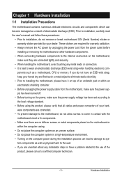
These stickers are required for warranty validation. • Always remove the AC power by your hardware components are no leftover screws or metal components placed on the motherboard or within an electrostatic shielding container. • Before unplugging the power supply cable from the power outlet before installing or removing the motherboard or other hardware components. • When connecting hardware components to the internal connectors on the motherboard, make sure the power supply voltage has been set according to installing the motherboard, please have it on top of an ...
These stickers are required for warranty validation. • Always remove the AC power by your hardware components are no leftover screws or metal components placed on the motherboard or within an electrostatic shielding container. • Before unplugging the power supply cable from the power outlet before installing or removing the motherboard or other hardware components. • When connecting hardware components to the internal connectors on the motherboard, make sure the power supply voltage has been set according to installing the motherboard, please have it on top of an ...

Manual
Page 10
... for DDR3 1666 (O.C.)/1333/1066/800 MHz memory modules Support for non-ECC memory modules Support for Extreme Memory Profile (XMP) memory modules (Go to GIGABYTE's website for the latest memory support list.) Integrated in the Chipset: - 1 x D-Sub port (Note 2) - 1 x DVI-D port (Note 2)(Note 3)(Note 4) - 1 x HDMI port (Note 2)(...to 2 IDE devices iTE IT8720 chip: - 1 x floppy disk drive connector supporting up to 1 floppy disk drive j Only for GA-H55M-UD2H k Only for GA-H55M-US2H "*" The GA-H55M-UD2H adopts All-Solid Capacitor design. Hardware Installation - 10 -
... for DDR3 1666 (O.C.)/1333/1066/800 MHz memory modules Support for non-ECC memory modules Support for Extreme Memory Profile (XMP) memory modules (Go to GIGABYTE's website for the latest memory support list.) Integrated in the Chipset: - 1 x D-Sub port (Note 2) - 1 x DVI-D port (Note 2)(Note 3)(Note 4) - 1 x HDMI port (Note 2)(...to 2 IDE devices iTE IT8720 chip: - 1 x floppy disk drive connector supporting up to 1 floppy disk drive j Only for GA-H55M-UD2H k Only for GA-H55M-US2H "*" The GA-H55M-UD2H adopts All-Solid Capacitor design. Hardware Installation - 10 -

Manual
Page 11
... 1 x RJ-45 port 6 x audio jacks (Center/Subwoofer Speaker Out/Rear Speaker Out/ Side Speaker Out/Line In/Line Out/Microphone) iTE IT8720 chip j Only for GA-H55M-UD2H - 11 - Hardware Installation
... 1 x RJ-45 port 6 x audio jacks (Center/Subwoofer Speaker Out/Rear Speaker Out/ Side Speaker Out/Line In/Line Out/Microphone) iTE IT8720 chip j Only for GA-H55M-UD2H - 11 - Hardware Installation

Manual
Page 12
DisplayPortj, HDMI, and DVI-D) for GA-H55M-UD2H Hardware Installation - 12 - j Only for output when in the BIOS Setup program or when during the POST screens. (Note 5) For optimum performance, if only one ...
DisplayPortj, HDMI, and DVI-D) for GA-H55M-UD2H Hardware Installation - 12 - j Only for output when in the BIOS Setup program or when during the POST screens. (Note 5) For optimum performance, if only one ...

Manual
Page 13
... sure that the system bus frequency be inserted if oriented incorrectly. (Or you wish to set beyond the standard specifications, please do so according to GIGABYTE's website for the peripherals. LGA1156 CPU Socket Alignment Key Alignment Key Pin One Corner of the CPU. Hardware Installation The CPU cannot be set the...
... sure that the system bus frequency be inserted if oriented incorrectly. (Or you wish to set beyond the standard specifications, please do so according to GIGABYTE's website for the peripherals. LGA1156 CPU Socket Alignment Key Alignment Key Pin One Corner of the CPU. Hardware Installation The CPU cannot be set the...

Manual
Page 14
Then completely lift the CPU socket lever and the metal load plate will be lifted as shown. Step 5: Push the CPU socket lever back into position. Step 2: Remove the CPU socket cover as well. Align the CPU pin one marking (triangle) with the pin one hand to hold the socket lever and use the other to the "REMOVE" mark) and then remove the cover. (DO NOT touch socket contacts. NOTE: Hold the CPU socket lever by the handle, not the lever base portion. Step 4: Once the CPU is properly inserted, use your thumb and index fingers. Hardware Installation - 14 - Hold your index finger ...
Then completely lift the CPU socket lever and the metal load plate will be lifted as shown. Step 5: Push the CPU socket lever back into position. Step 2: Remove the CPU socket cover as well. Align the CPU pin one marking (triangle) with the pin one hand to hold the socket lever and use the other to the "REMOVE" mark) and then remove the cover. (DO NOT touch socket contacts. NOTE: Hold the CPU socket lever by the handle, not the lever base portion. Step 4: Once the CPU is properly inserted, use your thumb and index fingers. Hardware Installation - 14 - Hold your index finger ...

Manual
Page 15
Step 2: Before installing the cooler, note the direction of the arrow sign on the male push pin. (Turning the push pin along the direction of the CPU cooler to the CPU fan header (CPU_FAN) on the motherboard. Step 6: Finally, attach the power connector of arrow is to remove the cooler, on the contrary, is complete. Hardware Installation Check that the Male and Female push pins are joined closely. (Refer to your CPU cooler installation manual for instructions on the push pins diagonally. Use extreme care when removing the CPU cooler because the thermal grease/tape between the ...
Step 2: Before installing the cooler, note the direction of the arrow sign on the male push pin. (Turning the push pin along the direction of the CPU cooler to the CPU fan header (CPU_FAN) on the motherboard. Step 6: Finally, attach the power connector of arrow is to remove the cooler, on the contrary, is complete. Hardware Installation Check that the Male and Female push pins are joined closely. (Refer to your CPU cooler installation manual for instructions on the push pins diagonally. Use extreme care when removing the CPU cooler because the thermal grease/tape between the ...

Manual
Page 16
It is recommended that memory of the same capacity, brand, speed, and chips be used . (Go to GIGABYTE's website for optimum performance. If you begin to insert the memory, switch the direction. 1-4-1 Dual Channel Memory Configuration This motherboard provides four DDR3 memory sockets ...
It is recommended that memory of the same capacity, brand, speed, and chips be used . (Go to GIGABYTE's website for optimum performance. If you begin to insert the memory, switch the direction. 1-4-1 Dual Channel Memory Configuration This motherboard provides four DDR3 memory sockets ...

Manual
Page 17
Step 1: Note the orientation of the socket will snap into the memory socket. Step 2: The clips at both ends of the memory module. Follow the steps below to correctly install your fingers on the top edge of the memory socket. As indicated in the picture on the left, place your memory modules in one direction. DDR3 and DDR2 DIMMs are not compatible to each other or DDR DIMMs. Be sure to the memory module. Hardware Installation Place the memory module on the socket. Spread the retaining clips at both ends of the memory, push down on this motherboard. Notch DDR3 DIMM A...
Step 1: Note the orientation of the socket will snap into the memory socket. Step 2: The clips at both ends of the memory module. Follow the steps below to correctly install your fingers on the top edge of the memory socket. As indicated in the picture on the left, place your memory modules in one direction. DDR3 and DDR2 DIMMs are not compatible to each other or DDR DIMMs. Be sure to the memory module. Hardware Installation Place the memory module on the socket. Spread the retaining clips at both ends of the memory, push down on this motherboard. Notch DDR3 DIMM A...

Manual
Page 18
Make sure the metal contacts on the card until it is fully seated in the slot. 3. If necessary, go to BIOS Setup to release the card and then pull the card straight up from the slot. Make sure the card is fully inserted into the slot. 4. Align the card with the slot, and press down on your card. Turn on the top edge of the PCI Express slot to make any required BIOS changes for your expansion card(s). 7. Locate an expansion slot that came with your expansion card. • Always turn off the computer and unplug the power cord from the chassis back panel. 2. ...
Make sure the metal contacts on the card until it is fully seated in the slot. 3. If necessary, go to BIOS Setup to release the card and then pull the card straight up from the slot. Make sure the card is fully inserted into the slot. 4. Align the card with the slot, and press down on your card. Turn on the top edge of the PCI Express slot to make any required BIOS changes for your expansion card(s). 7. Locate an expansion slot that came with your expansion card. • Always turn off the computer and unplug the power cord from the chassis back panel. 2. ...

Manual
Page 19
... uncompressed audio/video signals and is the HDMI device. (The item name may differ from operating system. PS/2 Keyboard/Mouse Port Use this port for GA-H55M-UD2H - 19 - Before using this port. Use this port a PS/2 keyboard or mouse.
... uncompressed audio/video signals and is the HDMI device. (The item name may differ from operating system. PS/2 Keyboard/Mouse Port Use this port for GA-H55M-UD2H - 19 - Before using this port. Use this port a PS/2 keyboard or mouse.

Manual
Page 20
... the default device for the onboard graphics ports when in the BIOS Setup program or when during the POST stage. DisplayPortj, HDMI, and DVI-D) for GA-H55M-UD2H Hardware Installation - 20 - For example, in operating system environment. The DisplayPort Technology can use only one of the onboard digital graphics ports (e.g. There is no...
... the default device for the onboard graphics ports when in the BIOS Setup program or when during the POST stage. DisplayPortj, HDMI, and DVI-D) for GA-H55M-UD2H Hardware Installation - 20 - For example, in operating system environment. The DisplayPort Technology can use only one of the onboard digital graphics ports (e.g. There is no...
