
Manual
Page 1
GA-H55M-UD2H/ GA-H55M-US2H LGA1156 socket motherboard for Intel® Core™ i7 processor family/ Intel® Core™ i5 processor family/ Intel® Core™ i3 processor family User's Manual Rev. 1002 12ME-H55MUD2-1002R
GA-H55M-UD2H/ GA-H55M-US2H LGA1156 socket motherboard for Intel® Core™ i7 processor family/ Intel® Core™ i5 processor family/ Intel® Core™ i3 processor family User's Manual Rev. 1002 12ME-H55MUD2-1002R

Manual
Page 7
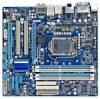
GA-H55M-UD2H/GA-H55M-US2H Motherboard Layout KB_USB ATX_12V VGA_DVI LGA1156 PHASE LED IT8720 DPj_HDMI_SPDIF ESATA_1394j_USB USB_LAN CPU_FAN IDE ATX FDD AUDIO F_AUDIO PCIEX16 GA-H55M-UD2H/ BAT GA-H55M-US2H DDR3_2 DDR3_1 DDR3_4 DDR3_3 PCI1 RTL8111D SPDIF_O SPDIF_I CODEC PCI2 PCIEX4 CD_IN SYS_FAN COMA Intel® H55 TSB43AB23j SATA2_0 JMicron JMB368 CLR_CMOS M_BIOS SATA2_2 SATA2_1 B_BIOS SATA2_4 SATA2_3 F_1394j F_USB2 F_USB3 F_USB1 F_PANEL j Only for GA-H55M-UD2H "*" The GA-H55M-UD2H adopts All-Solid Capacitor design. - 7 -
GA-H55M-UD2H/GA-H55M-US2H Motherboard Layout KB_USB ATX_12V VGA_DVI LGA1156 PHASE LED IT8720 DPj_HDMI_SPDIF ESATA_1394j_USB USB_LAN CPU_FAN IDE ATX FDD AUDIO F_AUDIO PCIEX16 GA-H55M-UD2H/ BAT GA-H55M-US2H DDR3_2 DDR3_1 DDR3_4 DDR3_3 PCI1 RTL8111D SPDIF_O SPDIF_I CODEC PCI2 PCIEX4 CD_IN SYS_FAN COMA Intel® H55 TSB43AB23j SATA2_0 JMicron JMB368 CLR_CMOS M_BIOS SATA2_2 SATA2_1 B_BIOS SATA2_4 SATA2_3 F_1394j F_USB2 F_USB3 F_USB1 F_PANEL j Only for GA-H55M-UD2H "*" The GA-H55M-UD2H adopts All-Solid Capacitor design. - 7 -

Manual
Page 8
Block Diagram 1 PCI Express x16 LGA1156 CPU CPU CLK+/- (133 MHz) DDR3 1666 (O.C.)/1333/1066/800 MHz Dual Channel Memory PCIe CLK (100 MHz) x16 PCI Express Bus 1 PCI Express x4 ... 2 PCI PCI CLK (33 MHz) j Only for output when in the BIOS Setup program or when during the POST screens. - 8 - DisplayPortj, HDMI, and DVI-D) for GA-H55M-UD2H (Note) You can use only one of the onboard digital graphics ports (e.g.
Block Diagram 1 PCI Express x16 LGA1156 CPU CPU CLK+/- (133 MHz) DDR3 1666 (O.C.)/1333/1066/800 MHz Dual Channel Memory PCIe CLK (100 MHz) x16 PCI Express Bus 1 PCI Express x4 ... 2 PCI PCI CLK (33 MHz) j Only for output when in the BIOS Setup program or when during the POST screens. - 8 - DisplayPortj, HDMI, and DVI-D) for GA-H55M-UD2H (Note) You can use only one of the onboard digital graphics ports (e.g.

Manual
Page 10
...; Core™ i7 series processor/Intel® Core™ i5 series processor/ Intel® Core™ i3 series processor in the LGA1156 package (Go to GIGABYTE's website for the latest CPU support list.) L3 cache varies with CPU Chipset Intel® H55 Express Chipset Memory Onboard Graphics ...33 and up to 2 IDE devices iTE IT8720 chip: - 1 x floppy disk drive connector supporting up to 1 floppy disk drive j Only for GA-H55M-UD2H k Only for GA-H55M-US2H "*" The GA-H55M-UD2H adopts All-Solid Capacitor design. Hardware Installation - 10 -
...; Core™ i7 series processor/Intel® Core™ i5 series processor/ Intel® Core™ i3 series processor in the LGA1156 package (Go to GIGABYTE's website for the latest CPU support list.) L3 cache varies with CPU Chipset Intel® H55 Express Chipset Memory Onboard Graphics ...33 and up to 2 IDE devices iTE IT8720 chip: - 1 x floppy disk drive connector supporting up to 1 floppy disk drive j Only for GA-H55M-UD2H k Only for GA-H55M-US2H "*" The GA-H55M-UD2H adopts All-Solid Capacitor design. Hardware Installation - 10 -

Manual
Page 13
... the CPU cooler is not recommended that the motherboard supports the CPU. (Go to GIGABYTE's website for the peripherals. It is not installed, otherwise overheating and dam- LGA1156 CPU Socket Alignment Key Alignment Key Pin One Corner of the CPU Socket LGA1156 CPU Notch Notch Triangle Pin One Marking on the CPU - 13 -
... the CPU cooler is not recommended that the motherboard supports the CPU. (Go to GIGABYTE's website for the peripherals. It is not installed, otherwise overheating and dam- LGA1156 CPU Socket Alignment Key Alignment Key Pin One Corner of the CPU Socket LGA1156 CPU Notch Notch Triangle Pin One Marking on the CPU - 13 -