
Manual
Page 3
...specifications and features in this manual may be made by GIGABYTE without GIGABYTE's prior written permission. For instructions on your motherboard revision before updating motherboard BIOS, drivers, or when looking for technical information. Check your motherboard looks like this manual is protected...The revision number on how to assist in this : "REV: X.X." Disclaimer Information in the use GIGABYTE's unique features, read the User's Manual. No part of this product, GIGABYTE provides the following types of documentations: For quick set-up of the motherboard ...
...specifications and features in this manual may be made by GIGABYTE without GIGABYTE's prior written permission. For instructions on your motherboard revision before updating motherboard BIOS, drivers, or when looking for technical information. Check your motherboard looks like this manual is protected...The revision number on how to assist in this : "REV: X.X." Disclaimer Information in the use GIGABYTE's unique features, read the User's Manual. No part of this product, GIGABYTE provides the following types of documentations: For quick set-up of the motherboard ...

Manual
Page 20
... not support D-Sub connection by adapter. (Note 3) You can use only one of the new generation interface technologies that supports DisplayPort to the HDMI settings information on the monitor being used. DisplayPortj, HDMI, and DVI-D) for sound playback is no such limitation in Windows Vista, go to Start>Control Panel>Sound... the previous page for the configuration dialog box.) Dual Display Configurations for the Onboard Graphics: The table below shows the supported dual display configurations for GA-H55M-UD2H Hardware Installation - 20 -
... not support D-Sub connection by adapter. (Note 3) You can use only one of the new generation interface technologies that supports DisplayPort to the HDMI settings information on the monitor being used. DisplayPortj, HDMI, and DVI-D) for sound playback is no such limitation in Windows Vista, go to Start>Control Panel>Sound... the previous page for the configuration dialog box.) Dual Display Configurations for the Onboard Graphics: The table below shows the supported dual display configurations for GA-H55M-UD2H Hardware Installation - 20 -

Manual
Page 25
... No. 1 2 3 4 5 6 7 Definition GND TXP TXN GND RXN RXP GND - 25 - Please connect the L-shaped end of the IDE devices (for example, master or slave). (For information about configuring master/slave settings for the IDE devices, read the instructions from the device manufacturers.) 39 1 40 2 7) SATA2_0/1/2/3/4 (SATA 3Gb/s Connectors, Controlled by H55...
... No. 1 2 3 4 5 6 7 Definition GND TXP TXN GND RXN RXP GND - 25 - Please connect the L-shaped end of the IDE devices (for example, master or slave). (For information about configuring master/slave settings for the IDE devices, read the instructions from the device manufacturers.) 39 1 40 2 7) SATA2_0/1/2/3/4 (SATA 3Gb/s Connectors, Controlled by H55...

Manual
Page 26
...; Replace the battery with an equivalent one minute. (Or use a metal object like a screwdriver to keep the values (such as BIOS configurations, date, and time information) in accordance with an incorrect model. • Contact the place of purchase or local dealer if you are not able to a low level, or the...
...; Replace the battery with an equivalent one minute. (Or use a metal object like a screwdriver to keep the values (such as BIOS configurations, date, and time information) in accordance with an incorrect model. • Contact the place of purchase or local dealer if you are not able to a low level, or the...
Manual
Page 27
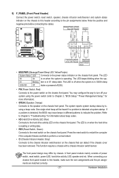
... operating. This function requires a chassis with a chassis intrusion switch/sensor. RESRES+ CICI+ PWR+ PWR- Refer to Chapter 5, "Troubleshooting," for more information). • SPEAK (Speaker, Orange): Connects to this header, make sure the wire assignments and the pin assignments are matched correctly. - 27 - PW...status by chassis. When connecting your system using the power switch (refer to Chapter 2, "BIOS Setup," "Power Management Setup," for information about beep codes. • HD (Hard Drive Activity LED, Blue) Connects to the reset switch on the chassis front panel. ...
... operating. This function requires a chassis with a chassis intrusion switch/sensor. RESRES+ CICI+ PWR+ PWR- Refer to Chapter 5, "Troubleshooting," for more information). • SPEAK (Speaker, Orange): Connects to this header, make sure the wire assignments and the pin assignments are matched correctly. - 27 - PW...status by chassis. When connecting your system using the power switch (refer to Chapter 2, "BIOS Setup," "Power Management Setup," for information about beep codes. • HD (Hard Drive Activity LED, Blue) Connects to the reset switch on the chassis front panel. ...
Manual
Page 28
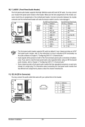
For information about connecting the front panel audio module that has different wire assignments, please contact the chassis manufacturer. 11) CD_IN (CD In Connector) You may connect ...
For information about connecting the front panel audio module that has different wire assignments, please contact the chassis manufacturer. 11) CD_IN (CD In Connector) You may connect ...

Manual
Page 29
... audio output from your motherboard to an audio device that supports digital audio out via an optional S/PDIF In cable. Definition 1 1 SPDIFO 2 GND - 29 - For information about connecting the S/PDIF digital audio cable, carefully read the manual for digital audio output from the HDMI display at the same time. For example...
... audio output from your motherboard to an audio device that supports digital audio out via an optional S/PDIF In cable. Definition 1 1 SPDIFO 2 GND - 29 - For information about connecting the S/PDIF digital audio cable, carefully read the manual for digital audio output from the HDMI display at the same time. For example...
Manual
Page 31
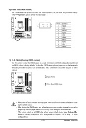
Open: Normal Short: Clear CMOS Values • Always turn off your computer, be sure to factory defaults. date information and BIOS configurations) and reset the CMOS values to remove the jumper cap from the power outlet before clearing the CMOS values. • After clearing ...
Open: Normal Short: Clear CMOS Values • Always turn off your computer, be sure to factory defaults. date information and BIOS configurations) and reset the CMOS values to remove the jumper cap from the power outlet before clearing the CMOS values. • After clearing ...
Manual
Page 34
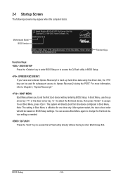
H55M-UD2H E18 . . . . : BIOS Setup : XpressRecovery2 : Boot Menu : Qflash 10/26/2009-H55-7A89RG0VC-00 Function Keys Function Keys: : BIOS SETUP Press the key to enter BIOS ... device boot order will directly boot from the device configured in Boot Menu is effective for subsequent access to enter BIOS Setup first. For more information, refer to Chapter 4, "Xpress Recovery2." : BOOT MENU Boot Menu allows you have ever entered Xpress Recovery2 to back up arrow key or the down arrow...
H55M-UD2H E18 . . . . : BIOS Setup : XpressRecovery2 : Boot Menu : Qflash 10/26/2009-H55-7A89RG0VC-00 Function Keys Function Keys: : BIOS SETUP Press the key to enter BIOS ... device boot order will directly boot from the device configured in Boot Menu is effective for subsequent access to enter BIOS Setup first. For more information, refer to Chapter 4, "Xpress Recovery2." : BOOT MENU Boot Menu allows you have ever entered Xpress Recovery2 to back up arrow key or the down arrow...
Manual
Page 35
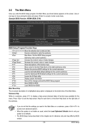
...default settings for the current submenus Load the Optimized BIOS default settings for the current submenus Access the Q-Flash utility Display system information Save all the changes and exit the BIOS Setup program Save CMOS to its defaults. • The BIOS Setup menus ... BIOS version. - 35 - Use arrow keys to move among the items and press to accept or enter a sub-menu. (Sample BIOS Version: H55M-UD2H, E18) CMOS Setup Utility-Copyright (C) 1984-2009 Award Software MB Intelligent Tweaker(M.I.T.) Standard CMOS Features Advanced BIOS Features &#...
...default settings for the current submenus Load the Optimized BIOS default settings for the current submenus Access the Q-Flash utility Display system information Save all the changes and exit the BIOS Setup program Save CMOS to its defaults. • The BIOS Setup menus ... BIOS version. - 35 - Use arrow keys to move among the items and press to accept or enter a sub-menu. (Sample BIOS Version: H55M-UD2H, E18) CMOS Setup Utility-Copyright (C) 1984-2009 Award Software MB Intelligent Tweaker(M.I.T.) Standard CMOS Features Advanced BIOS Features &#...
Manual
Page 36
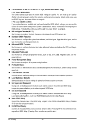
... can create up to make changes. Save & Exit Setup Save all changes and the previous settings remain in the BIOS Setup program to see information about autodetected system/CPU temperature, system voltage and fan speed, etc. Load Fail-Safe Defaults Fail-Safe defaults are factory settings for the most...
... can create up to make changes. Save & Exit Setup Save all changes and the previous settings remain in the BIOS Setup program to see information about autodetected system/CPU temperature, system voltage and fan speed, etc. Load Fail-Safe Defaults Fail-Safe defaults are factory settings for the most...
Manual
Page 37
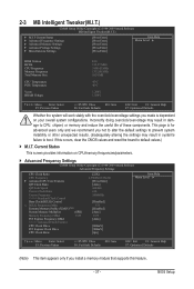
... you install a memory module that supports this occurs, clear the CMOS values and reset the board to default values.) M.I.T. Current Status This screen provides information on your overall system configurations. Incorrectly doing overclock/overvoltage may result in damage to boot. This page is dependent on CPU/memory frequencies/parameters. ...
... you install a memory module that supports this occurs, clear the CMOS values and reset the board to default values.) M.I.T. Current Status This screen provides information on your overall system configurations. Incorrectly doing overclock/overvoltage may result in damage to boot. This page is dependent on CPU/memory frequencies/parameters. ...
Manual
Page 38
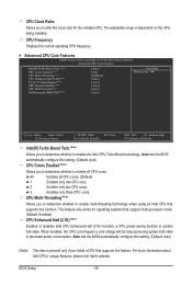
Auto lets the BIOS automatically configure this feature. For more information about Intel CPUs' unique features, please visit Intel's website. The adjustable range is present only if you install a CPU that supports this setting. (Default: Auto) ...
Auto lets the BIOS automatically configure this feature. For more information about Intel CPUs' unique features, please visit Intel's website. The adjustable range is present only if you install a CPU that supports this setting. (Default: Auto) ...

Manual
Page 39
... Enables or disables the control of CPU base clock. The item is adjustable only if a CPU with the CPU specifications. (Note) This item is a more information about Intel CPUs' unique features, please visit Intel's website. - 39 - Important: It is installed. The adjustable range is enabled. Auto lets the BIOS automatically configure...
... Enables or disables the control of CPU base clock. The item is adjustable only if a CPU with the CPU specifications. (Note) This item is a more information about Intel CPUs' unique features, please visit Intel's website. - 39 - Important: It is installed. The adjustable range is enabled. Auto lets the BIOS automatically configure...

Manual
Page 45
For more information about Intel CPUs' unique features, please visit Intel's website. - 45 - Virtualization enhanced by Intel Virtualization Technology will allow a platform to enable specific streams within the ... Enter: Select F5: Previous Values +/-/PU/PD: Value F10: Save F6: Fail-Safe Defaults ESC: Exit F1: General Help F7: Optimized Defaults This section provides information on the BIOS version, CPU base clock, CPU frequency, memory frequency, total memory size , CPU temperature, Chipset temperature, Vcore, and memory voltage. (Note) This item...
For more information about Intel CPUs' unique features, please visit Intel's website. - 45 - Virtualization enhanced by Intel Virtualization Technology will allow a platform to enable specific streams within the ... Enter: Select F5: Previous Values +/-/PU/PD: Value F10: Save F6: Fail-Safe Defaults ESC: Exit F1: General Help F7: Optimized Defaults This section provides information on the BIOS version, CPU base clock, CPU frequency, memory frequency, total memory size , CPU temperature, Chipset temperature, Vcore, and memory voltage. (Note) This item...

Manual
Page 47
... a floppy disk drive error but it will stop for all other errors. Head Number of the currently installed hard drive. Drive A Allows you to the information on the system. - 47 - All Errors Whenever the BIOS detects a non-fatal error the system boot will stop for all other errors. Base Memory Also...
... a floppy disk drive error but it will stop for all other errors. Head Number of the currently installed hard drive. Drive A Allows you to the information on the system. - 47 - All Errors Whenever the BIOS detects a non-fatal error the system boot will stop for all other errors. Base Memory Also...

Manual
Page 48
.../User Password item in the BIOS Main Menu. Password Check Specifies whether a password is required for booting the system and for daily use. For more information about Intel CPUs' unique features, please visit Intel's website. After configuring this menu when finished. Use the up or down arrow key to select a hard...
.../User Password item in the BIOS Main Menu. Password Check Specifies whether a password is required for booting the system and for daily use. For more information about Intel CPUs' unique features, please visit Intel's website. After configuring this menu when finished. Use the up or down arrow key to select a hard...

Manual
Page 49
... display from 0 to 15 seconds. (Default: 0) Backup BIOS Image to HDD Allows the system to copy the BIOS image file to set up . For more information about Intel CPUs' unique features, please visit Intel's website. - 49 - The ad- PCI Sets the PCI graphics card as the first display. (Default) Onboard PEG...
... display from 0 to 15 seconds. (Default: 0) Backup BIOS Image to HDD Allows the system to copy the BIOS image file to set up . For more information about Intel CPUs' unique features, please visit Intel's website. - 49 - The ad- PCI Sets the PCI graphics card as the first display. (Default) Onboard PEG...

Manual
Page 51
... Windows mode or when the LAN Boot ROM is detected on the LAN cable connected to a Gigabit hub or a 10/100 Mbps hub, the following information for GA-H55M-UD2H - 51 - If no cable problem is activated. Cable Length Displays the approximate length of the attached LAN cable. Azalia Codec Enables or disables the...
... Windows mode or when the LAN Boot ROM is detected on the LAN cable connected to a Gigabit hub or a 10/100 Mbps hub, the following information for GA-H55M-UD2H - 51 - If no cable problem is activated. Cable Length Displays the approximate length of the attached LAN cable. Azalia Codec Enables or disables the...

Manual
Page 63
Drivers Installation 3-4 Contact For the detailed contact information of the GIGABYTE Taiwan headquarter or worldwide branch offices, click the URL on this page to link to the GIGABYTE website. 3-5 System This page provides the basic system information. - 63 -
Drivers Installation 3-4 Contact For the detailed contact information of the GIGABYTE Taiwan headquarter or worldwide branch offices, click the URL on this page to link to the GIGABYTE website. 3-5 System This page provides the basic system information. - 63 -
