Manual
Page 4
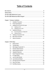
Table of Contents Box Contents...6 Optional Items...6 GA-H55-USB3 Motherboard Layout 7 GA-H55-USB3 Motherboard Block Diagram 8 Chapter 1 Hardware Installation 9 1-1 Installation Precautions 9 1-2 Product Specifications 10 1-3 Installing the CPU and CPU Cooler 13 1-3-1 Installing the CPU 13 1-3-2 Installing the CPU Cooler 15 1-4 Installing the Memory 16 1-4-1 Dual Channel Memory Configuration 16 1-4-2 Installing a Memory 17 1-5 Installing an Expansion Card 18 1-6 Back...
Table of Contents Box Contents...6 Optional Items...6 GA-H55-USB3 Motherboard Layout 7 GA-H55-USB3 Motherboard Block Diagram 8 Chapter 1 Hardware Installation 9 1-1 Installation Precautions 9 1-2 Product Specifications 10 1-3 Installing the CPU and CPU Cooler 13 1-3-1 Installing the CPU 13 1-3-2 Installing the CPU Cooler 15 1-4 Installing the Memory 16 1-4-1 Dual Channel Memory Configuration 16 1-4-2 Installing a Memory 17 1-5 Installing an Expansion Card 18 1-6 Back...
Manual
Page 8
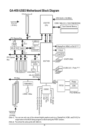
GA-H55-USB3 Motherboard Block Diagram 1 PCI Express x16 CPU CLK+/- (133 MHz) PCIe CLK (100 MHz) LGA1156 CPU DDR3 1666 (O.C.)/1333/1066/800 MHz Dual Channel Memory DMI Interface FDI Interface PCI Express Bus LAN RJ45 x16 x1 Gen 2 2 USB 3.0 RTL8111D Switch x1 Gen 1 NEC D720200F1 PCI Express X1 X1 X1 Bus x1 GIGABYTE... SATA2 Intel® H55 3 PCI Express x1 2 SATA 3Gb/s PCI...
GA-H55-USB3 Motherboard Block Diagram 1 PCI Express x16 CPU CLK+/- (133 MHz) PCIe CLK (100 MHz) LGA1156 CPU DDR3 1666 (O.C.)/1333/1066/800 MHz Dual Channel Memory DMI Interface FDI Interface PCI Express Bus LAN RJ45 x16 x1 Gen 2 2 USB 3.0 RTL8111D Switch x1 Gen 1 NEC D720200F1 PCI Express X1 X1 X1 Bus x1 GIGABYTE... SATA2 Intel® H55 3 PCI Express x1 2 SATA 3Gb/s PCI...

Manual
Page 9
... hardware components. • When connecting hardware components to wear an electrostatic discharge (ESD) wrist strap when handling electronic com- ponents such as a motherboard, CPU or memory. If you are connected tightly and securely. • When handling the motherboard, avoid touching any installation steps or have it on the motherboard, make sure...
... hardware components. • When connecting hardware components to wear an electrostatic discharge (ESD) wrist strap when handling electronic com- ponents such as a motherboard, CPU or memory. If you are connected tightly and securely. • When handling the motherboard, avoid touching any installation steps or have it on the motherboard, make sure...
Manual
Page 10
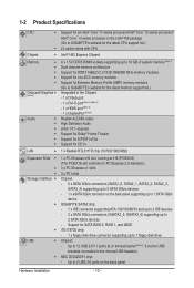
...; i5 series processor/ Intel® Core™ i3 series processor in the LGA1156 package (Go to GIGABYTE's website for the latest CPU support list.) L3 cache varies with CPU Chipset Intel® H55 Express Chipset Memory w Onboard Graphics (Note 2) Audio w 4 x 1.5V DDR3 DIMM sockets supporting...
...; i5 series processor/ Intel® Core™ i3 series processor in the LGA1156 package (Go to GIGABYTE's website for the latest CPU support list.) L3 cache varies with CPU Chipset Intel® H55 Express Chipset Memory w Onboard Graphics (Note 2) Audio w 4 x 1.5V DDR3 DIMM sockets supporting...

Manual
Page 12
... ports with integrated graphics. (Note 3) The DVI-D port does not support D-Sub connection by adapter. (Note 4) You can use only one of physical memory is installed, the actual memory size displayed will be less than 4 GB. (Note 2) To use the onboard DisplayPort, HDMI, DVI-D, and D-Sub ports, you must install an Intel...
... ports with integrated graphics. (Note 3) The DVI-D port does not support D-Sub connection by adapter. (Note 4) You can use only one of physical memory is installed, the actual memory size displayed will be less than 4 GB. (Note 2) To use the onboard DisplayPort, HDMI, DVI-D, and D-Sub ports, you must install an Intel...
Manual
Page 13
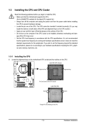
... CPU support list.) • Always turn on the computer if the CPU cooler is not recommended that the motherboard supports the CPU. (Go to GIGABYTE's website for the peripherals. It is not installed, otherwise overheating and dam- Hardware Installation age of the CPU. • Do not turn off ...CPU. If you wish to set beyond the standard specifications, please do so according to your hardware specifications including the CPU, graphics card, memory, hard drive, etc. 1-3-1 Installing the CPU A. Locate the alignment keys on the motherboard CPU socket and the notches on the CPU.
... CPU support list.) • Always turn on the computer if the CPU cooler is not recommended that the motherboard supports the CPU. (Go to GIGABYTE's website for the peripherals. It is not installed, otherwise overheating and dam- Hardware Installation age of the CPU. • Do not turn off ...CPU. If you wish to set beyond the standard specifications, please do so according to your hardware specifications including the CPU, graphics card, memory, hard drive, etc. 1-3-1 Installing the CPU A. Locate the alignment keys on the motherboard CPU socket and the notches on the CPU.
Manual
Page 16
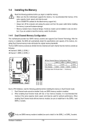
..., it in the DDR3_1 or DDR3_3 sockets. If only one DDR3 memory module is recommended that memory of the same capacity, brand, speed, and chips be used . (Go to GIGABYTE's website for optimum performance. Four Modules DS/SS DS/SS DS/SS DDR3_3 DS/SS DS/SS (SS=Single-...Sided, DS=Double-Sided, "- -"=No Memory) DDR3_2 DDR3_1 DDR3_4 DDR3_3 Due to insert the memory, switch the direction. 1-4-1 Dual Channel Memory Configuration This motherboard provides four DDR3...
..., it in the DDR3_1 or DDR3_3 sockets. If only one DDR3 memory module is recommended that memory of the same capacity, brand, speed, and chips be used . (Go to GIGABYTE's website for optimum performance. Four Modules DS/SS DS/SS DS/SS DDR3_3 DS/SS DS/SS (SS=Single-...Sided, DS=Double-Sided, "- -"=No Memory) DDR3_2 DDR3_1 DDR3_4 DDR3_3 Due to insert the memory, switch the direction. 1-4-1 Dual Channel Memory Configuration This motherboard provides four DDR3...
Manual
Page 17
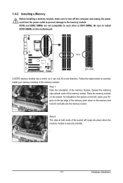
... Installation Step 2: The clips at both ends of the memory module. Step 1: Note the orientation of the socket will snap into the memory socket. Notch DDR3 DIMM A DDR3 memory module has a notch, so it vertically into place when the memory module is securely inserted. - 17 - Spread the retaining... clips at both ends of the memory, push down on the left, place your memory modules in one direction. Place the memory module on this motherboard. As indicated in the picture on the memory and insert it can only fit in the memory sockets. DDR3 and DDR2 DIMMs are ...
... Installation Step 2: The clips at both ends of the memory module. Step 1: Note the orientation of the socket will snap into the memory socket. Notch DDR3 DIMM A DDR3 memory module has a notch, so it vertically into place when the memory module is securely inserted. - 17 - Spread the retaining... clips at both ends of the memory, push down on the left, place your memory modules in one direction. Place the memory module on this motherboard. As indicated in the picture on the memory and insert it can only fit in the memory sockets. DDR3 and DDR2 DIMMs are ...
Manual
Page 36
... name (to erase the default profile name, use the SPACE key) and then press to complete. F12: Load CMOS from BIOS If your CPU, memory, etc. Standard CMOS Features Use this menu to the system and BIOS Setup.
... name (to erase the default profile name, use the SPACE key) and then press to complete. F12: Load CMOS from BIOS If your CPU, memory, etc. Standard CMOS Features Use this menu to the system and BIOS Setup.

Manual
Page 37
...] [Press Enter] [Press Enter] [Press Enter] Item Help Menu Level BIOS Version BCLK CPU Frequency Memory Frequency Total Memory Size E4 133.37 MHz 3067.78 MHz 1333.75 MHz 1024 MB CPU Temperature PCH Temperature 23.0oC 41.0oC... Clock Ratio QPI Link Speed >>>>> Standard Clock Control Base Clock(BCLK) Control x BCLK Frequency (Mhz) Extreme Memory Profile (X.M.P.) (Note 2) System Memory Multiplier (SPD) Memory Frequency (Mhz) 1333 PCI Express Frequency (Mhz) >>>>> Advanced Clock Control CPU Clock Drive PCI Express Clock Drive...
...] [Press Enter] [Press Enter] [Press Enter] Item Help Menu Level BIOS Version BCLK CPU Frequency Memory Frequency Total Memory Size E4 133.37 MHz 3067.78 MHz 1333.75 MHz 1024 MB CPU Temperature PCH Temperature 23.0oC 41.0oC... Clock Ratio QPI Link Speed >>>>> Standard Clock Control Base Clock(BCLK) Control x BCLK Frequency (Mhz) Extreme Memory Profile (X.M.P.) (Note 2) System Memory Multiplier (SPD) Memory Frequency (Mhz) 1333 PCI Express Frequency (Mhz) >>>>> Advanced Clock Control CPU Clock Drive PCI Express Clock Drive...

Manual
Page 40
.... Disabled Disables this feature. Options are : 700mV, 800mV, 900mV (default), 1000mV. System Memory Multiplier (SPD) Allows you to set the CPU clock prior to memory SPD data. (Default: Auto) Memory Frequency(Mhz) The first memory frequency value is automatically adjusted according to adjust the amplitude of the CPU and Chipset clock. BIOS Setup - 40...
.... Disabled Disables this feature. Options are : 700mV, 800mV, 900mV (default), 1000mV. System Memory Multiplier (SPD) Allows you to set the CPU clock prior to memory SPD data. (Default: Auto) Memory Frequency(Mhz) The first memory frequency value is automatically adjusted according to adjust the amplitude of the CPU and Chipset clock. BIOS Setup - 40...

Manual
Page 41
.../PD: Value F10: Save F6: Fail-Safe Defaults ESC: Exit F1: General Help F7: Optimized Defaults Extreme Memory Profile (X.M.P.) , (Note) System Memory Multiplier (SPD), Memory Frequency(Mhz) The settings under the same items on the Advanced Frequency Settings menu. Standard Lets the system operate at... to those under the three items above are : Auto (default), Quick, Expert. Profile DDR Voltage When using a non-XMP memory module or Extreme Memory Profile (X.M.P.) is set to Disabled, this feature. - 41 - Profile QPI Voltage The value displayed here is set to Profile1 ...
.../PD: Value F10: Save F6: Fail-Safe Defaults ESC: Exit F1: General Help F7: Optimized Defaults Extreme Memory Profile (X.M.P.) , (Note) System Memory Multiplier (SPD), Memory Frequency(Mhz) The settings under the same items on the Advanced Frequency Settings menu. Standard Lets the system operate at... to those under the three items above are : Auto (default), Quick, Expert. Profile DDR Voltage When using a non-XMP memory module or Extreme Memory Profile (X.M.P.) is set to Disabled, this feature. - 41 - Profile QPI Voltage The value displayed here is set to Profile1 ...

Manual
Page 45
...Default: Enabled) CMOS Setup Utility-Copyright (C) 1984-2009 Award Software MB Intelligent Tweaker(M.I.T.) } M.I.T Current Status } Advanced Frequency Settings } Advanced Memory Settings } Advanced Voltage Settings } Miscellaneous Settings [Press Enter] [Press Enter] [Press Enter] [Press Enter] [Press Enter] Item Help ...Menu Level BIOS Version BCLK CPU Frequency Memory Frequency Total Memory Size E4 133.37 MHz 3067.78 MHz 1333.75 MHz 1024 MB CPU Temperature PCH Temperature 23.0oC 41....
...Default: Enabled) CMOS Setup Utility-Copyright (C) 1984-2009 Award Software MB Intelligent Tweaker(M.I.T.) } M.I.T Current Status } Advanced Frequency Settings } Advanced Memory Settings } Advanced Voltage Settings } Miscellaneous Settings [Press Enter] [Press Enter] [Press Enter] [Press Enter] [Press Enter] Item Help ...Menu Level BIOS Version BCLK CPU Frequency Memory Frequency Total Memory Size E4 133.37 MHz 3067.78 MHz 1333.75 MHz 1024 MB CPU Temperature PCH Temperature 23.0oC 41....
Manual
Page 46
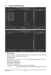
...[None] [None] [None] [None] [None] [None] [None] [None] [None] [None] Drive A [1.44M, 3.5"] Halt On [All, But Keyboard] Base Memory 640K Move Enter: Select F5: Previous Values +/-/PU/PD: Value F10: Save F6: Fail-Safe Defaults ESC: Exit F1: General Help F7: Optimized Defaults CMOS... Setup Utility-Copyright (C) 1984-2009 Award Software Standard CMOS Features Extended Memory Total Memory 827M 832M Item Help Menu Level Move Enter: Select F5: Previous Values +/-/PU/PD: Value F10: Save F6...
...[None] [None] [None] [None] [None] [None] [None] [None] [None] [None] Drive A [1.44M, 3.5"] Halt On [All, But Keyboard] Base Memory 640K Move Enter: Select F5: Previous Values +/-/PU/PD: Value F10: Save F6: Fail-Safe Defaults ESC: Exit F1: General Help F7: Optimized Defaults CMOS... Setup Utility-Copyright (C) 1984-2009 Award Software Standard CMOS Features Extended Memory Total Memory 827M 832M Item Help Menu Level Move Enter: Select F5: Previous Values +/-/PU/PD: Value F10: Save F6...

Manual
Page 47
..., Large. Halt On Allows you wish to enter the parameters manually, refer to the information on the system. - 47 - Total Memory The total amount of memory installed on the hard drive. BIOS Setup All, But Keyboard The system boot will not stop for a keyboard error but stop for all...But Disk/Key The system boot will not stop for a keyboard or a floppy disk drive error but stop for any error. Base Memory Also called conventional memory. Access Mode Sets the hard drive access mode. Drive A Allows you to manually enter the specifications of the hard drive when the...
..., Large. Halt On Allows you wish to enter the parameters manually, refer to the information on the system. - 47 - Total Memory The total amount of memory installed on the hard drive. BIOS Setup All, But Keyboard The system boot will not stop for a keyboard error but stop for all...But Disk/Key The system boot will not stop for a keyboard or a floppy disk drive error but stop for any error. Base Memory Also called conventional memory. Access Mode Sets the hard drive access mode. Drive A Allows you to manually enter the specifications of the hard drive when the...
Manual
Page 48
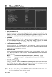
... entering the BIOS Setup program. (Default) System A password is required for booting the system and for daily use. BIOS Setup - 48 - to 3 (Note) No-Execute Memory Protect (Note) Delay For HDD (Secs) Full Screen LOGO Show Backup BIOS Image to report read/write errors of your system to HDD Init Display...
... entering the BIOS Setup program. (Default) System A password is required for booting the system and for daily use. BIOS Setup - 48 - to 3 (Note) No-Execute Memory Protect (Note) Delay For HDD (Secs) Full Screen LOGO Show Backup BIOS Image to report read/write errors of your system to HDD Init Display...
Manual
Page 49
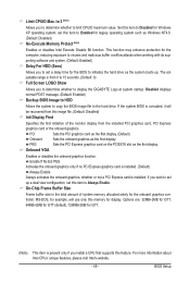
...Intel's website. - 49 - to 3 (Note) Allows you wish to initialize the hard drive as Windows NT4.0. (Default: Disabled) No-Execute Memory Protect (Note) Enables or disables Intel Execute Disable Bit function. Enable If No Ext PEG Activates the onboard graphics only if no PCI Express graphics... Enables or disables the onboard graphics function. set this item to display the GIGABYTE Logo at system startup. If the system BIOS is present only if you install a CPU that supports this memory for Windows XP operating system; BIOS Setup The adjustable range is installed. Disabled...
...Intel's website. - 49 - to 3 (Note) Allows you wish to initialize the hard drive as Windows NT4.0. (Default: Disabled) No-Execute Memory Protect (Note) Enables or disables Intel Execute Disable Bit function. Enable If No Ext PEG Activates the onboard graphics only if no PCI Express graphics... Enables or disables the onboard graphics function. set this item to display the GIGABYTE Logo at system startup. If the system BIOS is present only if you install a CPU that supports this memory for Windows XP operating system; BIOS Setup The adjustable range is installed. Disabled...

Manual
Page 54
... Keyboard Allows the system to be powered on the system. EuP Support Determines whether to let the system consume less than 1W power in a month. Memory The system returns to its last known awake state upon the return of the AC power. Resume by Alarm Determines whether to power on the...
... Keyboard Allows the system to be powered on the system. EuP Support Determines whether to let the system consume less than 1W power in a month. Memory The system returns to its last known awake state upon the return of the AC power. Resume by Alarm Determines whether to power on the...

Manual
Page 65
... on your system data and perform restoration of the hard drive, make sure to restore it . System Requirements: • At least 512 MB of system memory • VESA compatible graphics card • Windows XP with Xpress Recovery cannot be restored using Xpress Recovery2. • USB hard drives are not supported. •...
... on your system data and perform restoration of the hard drive, make sure to restore it . System Requirements: • At least 512 MB of system memory • VESA compatible graphics card • Windows XP with Xpress Recovery cannot be restored using Xpress Recovery2. • USB hard drives are not supported. •...
Manual
Page 72
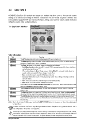
... tab allows you set temperature/fan speed alarm. Before you do overclock/overvoltage in EasyTune 6 may occur. You can select memory module on the CPU temperature thresholds you to change system clock settings and voltages settings using the sliders. • Save allows... Grayed-out area(s) indicates that allows users to fine-tune their system-related information without the need to install additional software. 4-3 EasyTune 6 GIGABYTE's EasyTune 6 is a simple and easy-to-use your own sound file (.wav file). (Note) Due to the hardware limitation, you...
... tab allows you set temperature/fan speed alarm. Before you do overclock/overvoltage in EasyTune 6 may occur. You can select memory module on the CPU temperature thresholds you to change system clock settings and voltages settings using the sliders. • Save allows... Grayed-out area(s) indicates that allows users to fine-tune their system-related information without the need to install additional software. 4-3 EasyTune 6 GIGABYTE's EasyTune 6 is a simple and easy-to-use your own sound file (.wav file). (Note) Due to the hardware limitation, you...


