
Manual
Page 1
GA-H55-UD3H LGA1156 socket motherboard for Intel® Core™ i7 processor family/ Intel® Core™ i5 processor family/ Intel® Core™ i3 processor family User's Manual Rev. 1001 12ME-H55UD3H-1001R
GA-H55-UD3H LGA1156 socket motherboard for Intel® Core™ i7 processor family/ Intel® Core™ i5 processor family/ Intel® Core™ i3 processor family User's Manual Rev. 1001 12ME-H55UD3H-1001R

Manual
Page 2
Motherboard GA-H55-UD3H Dec. 11, 2009 Motherboard GA-H55-UD3H Dec. 11, 2009
Motherboard GA-H55-UD3H Dec. 11, 2009 Motherboard GA-H55-UD3H Dec. 11, 2009

Manual
Page 3
...product-related information, check on our website at: http://www.gigabyte.com.tw Identifying Your Motherboard Revision The revision number on our website. The trademarks mentioned in this manual may be made by GIGABYTE without GIGABYTE's prior written permission. For instructions on how to the ...specifications and features in this product, GIGABYTE provides the following types of documentations: For quick set-up of GIGABYTE. Copyright © 2009 GIGA-BYTE TECHNOLOGY CO., LTD. Check your motherboard looks like this manual is protected by any form or...
...product-related information, check on our website at: http://www.gigabyte.com.tw Identifying Your Motherboard Revision The revision number on our website. The trademarks mentioned in this manual may be made by GIGABYTE without GIGABYTE's prior written permission. For instructions on how to the ...specifications and features in this product, GIGABYTE provides the following types of documentations: For quick set-up of GIGABYTE. Copyright © 2009 GIGA-BYTE TECHNOLOGY CO., LTD. Check your motherboard looks like this manual is protected by any form or...

Manual
Page 4
Table of Contents Box Contents...6 Optional Items...6 GA-H55-UD3H Motherboard Layout 7 Block Diagram...8 Chapter 1 Hardware Installation 9 1-1 Installation Precautions 9 1-2 Product Specifications 10 1-3 Installing the CPU and CPU Cooler 13 1-3-1 Installing the CPU 13 1-3-2 Installing the CPU ...
Table of Contents Box Contents...6 Optional Items...6 GA-H55-UD3H Motherboard Layout 7 Block Diagram...8 Chapter 1 Hardware Installation 9 1-1 Installation Precautions 9 1-2 Product Specifications 10 1-3 Installing the CPU and CPU Cooler 13 1-3-1 Installing the CPU 13 1-3-2 Installing the CPU ...

Manual
Page 6
...Part No. 12CF1-2SERPW-0*R) S/PDIF In cable (Part No. 12CR1-1SPDIN-0*R) COM port cable (Part No. 12CF1-1CM001-3*R) - 6 - Box Contents GA-H55-UD3H motherboard Motherboard driver disk User's Manual Quick Installation Guide One IDE cable Two SATA 3Gb/s cables I/O Shield • The box contents above are subject to change without... notice. • The motherboard image is for reference only and the actual items shall depend on the product package you obtain. The box contents are for reference only...
...Part No. 12CF1-2SERPW-0*R) S/PDIF In cable (Part No. 12CR1-1SPDIN-0*R) COM port cable (Part No. 12CF1-1CM001-3*R) - 6 - Box Contents GA-H55-UD3H motherboard Motherboard driver disk User's Manual Quick Installation Guide One IDE cable Two SATA 3Gb/s cables I/O Shield • The box contents above are subject to change without... notice. • The motherboard image is for reference only and the actual items shall depend on the product package you obtain. The box contents are for reference only...

Manual
Page 7
GA-H55-UD3H Motherboard Layout KB_USB VGA_DVI ATX_12V LGA1156 PHASE LED HDMI OPTICAL ATX R_USB USB_LAN CPU_FAN IT8213 IT8720 AUDIO F_AUDIO PCIEX1 RTL8111D PCIEX16 PCI1 CODEC PCI2 SPDIF_O SPDIF_I CD_IN PCI3 PCI4 PCIEX4 COMA BAT GA-H55-UD3H DDR3_2 DDR3_1 DDR3_4 DDR3_3 PWR_FAN Intel® H55 M_BIOS B_BIOS SATA2_3 SATA2_4 CLR_CMOS SATA2_0 SATA2_1 SATA2_2 SATA2_5 IDE F_USB1 SYS_FAN1 FDD SYS_FAN2 F_USB2 F_PANEL - 7 -
GA-H55-UD3H Motherboard Layout KB_USB VGA_DVI ATX_12V LGA1156 PHASE LED HDMI OPTICAL ATX R_USB USB_LAN CPU_FAN IT8213 IT8720 AUDIO F_AUDIO PCIEX1 RTL8111D PCIEX16 PCI1 CODEC PCI2 SPDIF_O SPDIF_I CD_IN PCI3 PCI4 PCIEX4 COMA BAT GA-H55-UD3H DDR3_2 DDR3_1 DDR3_4 DDR3_3 PWR_FAN Intel® H55 M_BIOS B_BIOS SATA2_3 SATA2_4 CLR_CMOS SATA2_0 SATA2_1 SATA2_2 SATA2_5 IDE F_USB1 SYS_FAN1 FDD SYS_FAN2 F_USB2 F_PANEL - 7 -

Manual
Page 9
...place the computer system on an uneven surface. • Do not place the computer system in a high-temperature environment. • Turning on the motherboard, make sure the power supply voltage has been set according to the local voltage standard. • Before using the product, please verify that all ..., carefully read the user's manual and follow these procedures: • Prior to installation, do not allow screws to come in contact with the motherboard circuit or its components. • Make sure there are uncertain about any metal leads or connectors. • It is best to wear an ...
...place the computer system on an uneven surface. • Do not place the computer system in a high-temperature environment. • Turning on the motherboard, make sure the power supply voltage has been set according to the local voltage standard. • Before using the product, please verify that all ..., carefully read the user's manual and follow these procedures: • Prior to installation, do not allow screws to come in contact with the motherboard circuit or its components. • Make sure there are uncertain about any metal leads or connectors. • It is best to wear an ...

Manual
Page 12
... it in the PCIEX16 slot. (Note 6) When the PCIEX1 slot is populated with integrated graphics. (Note 3) The DVI-D port does not support D-Sub connection by motherboard model. Hardware Installation - 12 - HDMI and DVI-D) for Microsoft® Windows® 7/Vista/XP Form Factor w ATX Form Factor; 30.5cm x 21.0cm (Note 1) Due...
... it in the PCIEX16 slot. (Note 6) When the PCIEX1 slot is populated with integrated graphics. (Note 3) The DVI-D port does not support D-Sub connection by motherboard model. Hardware Installation - 12 - HDMI and DVI-D) for Microsoft® Windows® 7/Vista/XP Form Factor w ATX Form Factor; 30.5cm x 21.0cm (Note 1) Due...

Manual
Page 13
... latest CPU support list.) • Always turn on the computer if the CPU cooler is not recommended that the motherboard supports the CPU. (Go to your hardware specifications including the CPU, graphics card, memory, hard drive, etc..... • Set the CPU host frequency in accordance with the CPU specifications. Locate the alignment keys on the motherboard CPU socket and the notches on the CPU - 13 - LGA1156 CPU Socket Alignment Key Alignment Key Pin One ...beyond the standard specifications, please do so according to GIGABYTE's website for the peripherals. Hardware Installation
... latest CPU support list.) • Always turn on the computer if the CPU cooler is not recommended that the motherboard supports the CPU. (Go to your hardware specifications including the CPU, graphics card, memory, hard drive, etc..... • Set the CPU host frequency in accordance with the CPU specifications. Locate the alignment keys on the motherboard CPU socket and the notches on the CPU - 13 - LGA1156 CPU Socket Alignment Key Alignment Key Pin One ...beyond the standard specifications, please do so according to GIGABYTE's website for the peripherals. Hardware Installation

Manual
Page 14
... completely lift the CPU socket lever and the metal load plate will be lifted as shown. Step 5: Push the CPU socket lever back into the motherboard CPU socket. Step 2: Remove the CPU socket cover as well. Step 4: Once the CPU is properly inserted, use one corner of the socket cover and...
... completely lift the CPU socket lever and the metal load plate will be lifted as shown. Step 5: Push the CPU socket lever back into the motherboard CPU socket. Step 2: Remove the CPU socket cover as well. Step 4: Once the CPU is properly inserted, use one corner of the socket cover and...

Manual
Page 15
Check that the Male and Female push pins are joined closely. (Refer to the CPU fan header (CPU_FAN) on the motherboard. If the push pin is inserted as the example cooler.) Step 1: Apply an even and thin layer of thermal grease on the surface of the ... above shows, the installation is to install.) Step 3: Place the cooler atop the CPU, aligning the four push pins through the pin holes on the motherboard. Inadequately removing the CPU cooler may adhere to the CPU. Hardware Installation Use extreme care when removing the CPU cooler because the thermal grease/tape...
Check that the Male and Female push pins are joined closely. (Refer to the CPU fan header (CPU_FAN) on the motherboard. If the push pin is inserted as the example cooler.) Step 1: Apply an even and thin layer of thermal grease on the surface of the ... above shows, the installation is to install.) Step 3: Place the cooler atop the CPU, aligning the four push pins through the pin holes on the motherboard. Inadequately removing the CPU cooler may adhere to the CPU. Hardware Installation Use extreme care when removing the CPU cooler because the thermal grease/tape...

Manual
Page 16
...enabling Dual Channel mode with two memory modules, be sure to insert the memory, switch the direction. 1-4-1 Dual Channel Memory Configuration This motherboard provides four DDR3 memory sockets and supports Dual Channel Technology. It is recommended to install the memory: • Make sure that memory... of the same capacity, brand, speed, and chips be used . (Go to GIGABYTE's website for optimum performance. Enabling Dual Channel memory mode will automatically detect the specifications and capacity of the same capacity, brand, speed, ...
...enabling Dual Channel mode with two memory modules, be sure to insert the memory, switch the direction. 1-4-1 Dual Channel Memory Configuration This motherboard provides four DDR3 memory sockets and supports Dual Channel Technology. It is recommended to install the memory: • Make sure that memory... of the same capacity, brand, speed, and chips be used . (Go to GIGABYTE's website for optimum performance. Enabling Dual Channel memory mode will automatically detect the specifications and capacity of the same capacity, brand, speed, ...

Manual
Page 17
Follow the steps below to install DDR3 DIMMs on this motherboard. DDR3 and DDR2 DIMMs are not compatible to each other or DDR DIMMs. Be sure to correctly install your fingers on the top edge of ...
Follow the steps below to install DDR3 DIMMs on this motherboard. DDR3 and DDR2 DIMMs are not compatible to each other or DDR DIMMs. Be sure to correctly install your fingers on the top edge of ...
Manual
Page 18
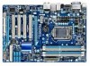
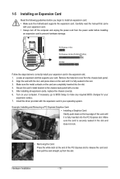
... is securely seated in the slot. 3. Turn on the top edge of the PCI Express slot to install an expansion card: • Make sure the motherboard supports the expansion card. If necessary, go to BIOS Setup to make any required BIOS changes for your expansion card. • Always turn off the...
... is securely seated in the slot. 3. Turn on the top edge of the PCI Express slot to install an expansion card: • Make sure the motherboard supports the expansion card. If necessary, go to BIOS Setup to make any required BIOS changes for your expansion card. • Always turn off the...

Manual
Page 20
... the connector. Only microphones still MUST be reconfigured to prevent an electrical short inside the cable connector. Do not rock it straight out from the motherboard. • When removing the cable, pull it side to side to perform different functions via the audio software. In addition to the default speakers settings...
... the connector. Only microphones still MUST be reconfigured to prevent an electrical short inside the cable connector. Do not rock it straight out from the motherboard. • When removing the cable, pull it side to side to perform different functions via the audio software. In addition to the default speakers settings...

Manual
Page 21
..., make sure your devices are compliant with the connectors you wish to connect. • Before installing the devices, be sure to the connector on the motherboard. - 21 -
..., make sure your devices are compliant with the connectors you wish to connect. • Before installing the devices, be sure to the connector on the motherboard. - 21 -

Manual
Page 22
... supply cable into pins under the protective cover when using a 2x12 power supply, remove the protective cover from the main power connector on the motherboard. Connect the power supply cable to the CPU. If a power supply is used that can withstand high power consumption be used (500W or greater..., the result can lead to an unstable or unbootable system. • The main power connector is turned off and all the components on the motherboard. 1/2) ATX_12V/ATX (2x2 12V Power Connector and 2x12 Main Power Connector) With the use of the power connector, the power supply can supply ...
... supply cable into pins under the protective cover when using a 2x12 power supply, remove the protective cover from the main power connector on the motherboard. Connect the power supply cable to the CPU. If a power supply is used that can withstand high power consumption be used (500W or greater..., the result can lead to an unstable or unbootable system. • The main power connector is turned off and all the components on the motherboard. 1/2) ATX_12V/ATX (2x2 12V Power Connector and 2x12 Main Power Connector) With the use of the power connector, the power supply can supply ...

Manual
Page 23
...1 GND 2 +12V 3 Sense • Be sure to connect fan cables to the fan headers to connect a floppy disk drive. The motherboard supports CPU fan speed control, which requires the use of different color. Do not place a jumper cap on the headers. 6) FDD (Floppy... MB. Definition 1 GND CPU_FAN 2 +12V / Speed Control 3 Sense 4 Speed Control 1 SYS_FAN2 SYS_FAN2: Pin No. 3/4/5) CPU_FAN/SYS_FAN1/SYS_FAN2/PWR_FAN (Fan Headers) The motherboard has a 4-pin CPU fan header (CPU_FAN), a 4-pin (SYS_FAN2) and two 3-pin (SYS_ FAN1) system fan headers, and a 3-pin power fan header (PWR_FAN)....
...1 GND 2 +12V 3 Sense • Be sure to connect fan cables to the fan headers to connect a floppy disk drive. The motherboard supports CPU fan speed control, which requires the use of different color. Do not place a jumper cap on the headers. 6) FDD (Floppy... MB. Definition 1 GND CPU_FAN 2 +12V / Speed Control 3 Sense 4 Speed Control 1 SYS_FAN2 SYS_FAN2: Pin No. 3/4/5) CPU_FAN/SYS_FAN1/SYS_FAN2/PWR_FAN (Fan Headers) The motherboard has a 4-pin CPU fan header (CPU_FAN), a 4-pin (SYS_FAN2) and two 3-pin (SYS_ FAN1) system fan headers, and a 3-pin power fan header (PWR_FAN)....

Manual
Page 26
... Audio Header) The front panel audio header supports Intel High Definition audio (HD) and AC'97 audio. Incorrect connection between the module connector and the motherboard header will be present on each wire instead of the...
... Audio Header) The front panel audio header supports Intel High Definition audio (HD) and AC'97 audio. Incorrect connection between the module connector and the motherboard header will be present on each wire instead of the...

Manual
Page 27
.... For example, some graphics cards may require you to use a S/PDIF digital audio cable for digital audio output from your motherboard to your graphics card if you wish to connect an HDMI display to certain expansion cards like graphics cards and sound cards. ...13) SPDIF_O (S/PDIF Out Header) This header supports digital S/PDIF Out and connects a S/PDIF digital audio cable (provided by expansion cards) for your motherboard to the graphics card and have digital audio output from your expansion card. Hardware Installation 12) SPDIF_I (S/PDIF In Header) This header supports digital S/PDIF...
.... For example, some graphics cards may require you to use a S/PDIF digital audio cable for digital audio output from your motherboard to your graphics card if you wish to connect an HDMI display to certain expansion cards like graphics cards and sound cards. ...13) SPDIF_O (S/PDIF Out Header) This header supports digital S/PDIF Out and connects a S/PDIF digital audio cable (provided by expansion cards) for your motherboard to the graphics card and have digital audio output from your expansion card. Hardware Installation 12) SPDIF_I (S/PDIF In Header) This header supports digital S/PDIF...


