Manual
Page 4
... Contents ...6 OptionalItems...6 GA-G41M-ES2L Motherboard Layout 7 Block Diagram...8 Chapter 1 Hardware Installation 9 1-1 Installation Precautions 9 1-2 Product Specifications 10 1-3 Installing the CPU and CPU Cooler 13 1-3-1 Installing the CPU 13 1-3-2 Installing the CPU Cooler 15 1-4 Installing the Memory 16 1-4-1 Dual Channel Memory Configuration 16 1-4-2 Installing a Memory 17 1-5 Installing an Expansion Card 18 1-6 Back Panel Connectors 19...
... Contents ...6 OptionalItems...6 GA-G41M-ES2L Motherboard Layout 7 Block Diagram...8 Chapter 1 Hardware Installation 9 1-1 Installation Precautions 9 1-2 Product Specifications 10 1-3 Installing the CPU and CPU Cooler 13 1-3-1 Installing the CPU 13 1-3-2 Installing the CPU Cooler 15 1-4 Installing the Memory 16 1-4-1 Dual Channel Memory Configuration 16 1-4-2 Installing a Memory 17 1-5 Installing an Expansion Card 18 1-6 Back Panel Connectors 19...
Manual
Page 10
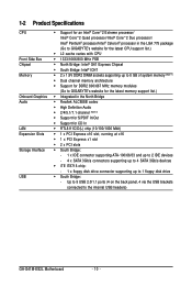
...to 8 GB of system memory (Note 1) Dual channel memory architecture Support for DDR2 800/667 MHz memory modules (Go to GIGABYTE's website for the latest memory support list.) Integrated in the North Bridge Realtek ALC888B codec High Definition Audio ... up to 4 SATA 3Gb/s devices iTE IT8718 chip: - 1 x floppy disk drive connector supporting up to the internal USB headers) GA-G41M-ES2L Motherboard - 10 - Up to 8 USB 2.0/1.1 ports (4 on the back panel, 4 via the USB brackets connected to 1 floppy disk drive South Bridge: -
...to 8 GB of system memory (Note 1) Dual channel memory architecture Support for DDR2 800/667 MHz memory modules (Go to GIGABYTE's website for the latest memory support list.) Integrated in the North Bridge Realtek ALC888B codec High Definition Audio ... up to 4 SATA 3Gb/s devices iTE IT8718 chip: - 1 x floppy disk drive connector supporting up to the internal USB headers) GA-G41M-ES2L Motherboard - 10 - Up to 8 USB 2.0/1.1 ports (4 on the back panel, 4 via the USB brackets connected to 1 floppy disk drive South Bridge: -
Manual
Page 11
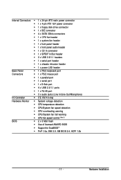
...IDE connector 4 x SATA 3Gb/s connectors 1 x CPU fan header 1 x system fan header 1 x front panel header 1 x front panel audio header 1 x CD In connector 1 x S/PDIF In/Out header 2 x USB 2.0/1.1 headers 1 ...x serial port header 1 x chassis intrusion header 1 x power LED header Back Panel 1 x PS/2 keyboard port Connectors 1 x PS/2 mouse port 1 x parallel port 1 x serial port 1 x...
...IDE connector 4 x SATA 3Gb/s connectors 1 x CPU fan header 1 x system fan header 1 x front panel header 1 x front panel audio header 1 x CD In connector 1 x S/PDIF In/Out header 2 x USB 2.0/1.1 headers 1 ...x serial port header 1 x chassis intrusion header 1 x power LED header Back Panel 1 x PS/2 keyboard port Connectors 1 x PS/2 mouse port 1 x parallel port 1 x serial port 1 x...
Manual
Page 12
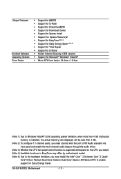
GA-G41M-ES2L Motherboard - 12 - Unique Features Bundled Software Operating System Form Factor Support for @BIOS Support for Q-Flash Support for Virtual DualBIOS Support ... memory size displayed will be less than 4 GB. (Note 2) To configure 7.1-channel audio, you need connect with the port of HD Audio standard via front panel and enable the multi-channel audio feature through the audio driver. (Note 3) Whether the CPU fan speed control function is supported will depend on the...
GA-G41M-ES2L Motherboard - 12 - Unique Features Bundled Software Operating System Form Factor Support for @BIOS Support for Q-Flash Support for Virtual DualBIOS Support ... memory size displayed will be less than 4 GB. (Note 2) To configure 7.1-channel audio, you need connect with the port of HD Audio standard via front panel and enable the multi-channel audio feature through the audio driver. (Note 3) Whether the CPU fan speed control function is supported will depend on the...
Manual
Page 18
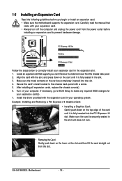
...correctly install your expansion card. • Always turn off the computer and unplug the power cord from the chassis back panel. 2. After installing all expansion cards, replace the chassis cover(s). 6. Locate an expansion slot that came with a screw.... 5. If necessary, go to BIOS Setup to the chassis back panel with your expansion card in the slot. 3. Install the driver provided with the slot, and press down on ...down on the slot and then lift the card straight out from the slot. GA-G41M-ES2L Motherboard - 18 -
...correctly install your expansion card. • Always turn off the computer and unplug the power cord from the chassis back panel. 2. After installing all expansion cards, replace the chassis cover(s). 6. Locate an expansion slot that came with a screw.... 5. If necessary, go to BIOS Setup to the chassis back panel with your expansion card in the slot. 3. Install the driver provided with the slot, and press down on ...down on the slot and then lift the card straight out from the slot. GA-G41M-ES2L Motherboard - 18 -
Manual
Page 19
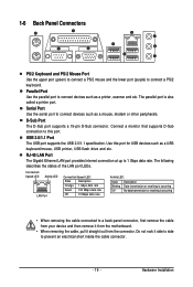
1-6 Back Panel Connectors PS/2 Keyboard and PS/2 Mouse Port Use the upper port (green) to connect a PS/2 mouse and the lower port (purple) to 1 Gbps data rate. ... port provides Internet connection at up to connect a PS/2 keyboard. Hardware Installation The parallel port is occurring • When removing the cable connected to a back panel connector, first remove the cable from your device and then remove it from the motherboard. • When removing the cable, pull it side to side...
1-6 Back Panel Connectors PS/2 Keyboard and PS/2 Mouse Port Use the upper port (green) to connect a PS/2 mouse and the lower port (purple) to 1 Gbps data rate. ... port provides Internet connection at up to connect a PS/2 keyboard. Hardware Installation The parallel port is occurring • When removing the cable connected to a back panel connector, first remove the cable from your device and then remove it from the motherboard. • When removing the cable, pull it side to side...
Manual
Page 20
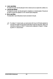
... need connect with the port of HD Audio standard via front panel and enable the multi-channel audio feature through the audio driver. Mic In Jack (Pink) The default Mic in jack. Use this audio jack for a headphone or 2-channel speaker. GA-G41M-ES2L Motherboard - 20 - This jack can be connected to the instructions...
... need connect with the port of HD Audio standard via front panel and enable the multi-channel audio feature through the audio driver. Mic In Jack (Pink) The default Mic in jack. Use this audio jack for a headphone or 2-channel speaker. GA-G41M-ES2L Motherboard - 20 - This jack can be connected to the instructions...
Manual
Page 26
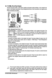
...heard if no problem is in S3/S4/S5 Off S3/S4 sleep state or powered off your chassis front panel module to this header according to the pin assignments below. GA-G41M-ES2L Motherboard - 26 - The S0 On LED is detected, the BIOS may issue beeps in S1 sleep state.... If a problem is on the chassis front panel. You may differ by issuing a beep code. Refer to Chapter 5, "Troubleshooting," for more information)....
...heard if no problem is in S3/S4/S5 Off S3/S4 sleep state or powered off your chassis front panel module to this header according to the pin assignments below. GA-G41M-ES2L Motherboard - 26 - The S0 On LED is detected, the BIOS may issue beeps in S1 sleep state.... If a problem is on the chassis front panel. You may differ by issuing a beep code. Refer to Chapter 5, "Troubleshooting," for more information)....

Manual
Page 27
... Pin No. Hardware Installation You may connect the audio cable that has separated connectors on both of the front and back panel audio connections simultaneously. Incorrect connection between the module connector and the motherboard header will be present on each wire instead of the... assignments, please contact the chassis manufacturer. 12) CD_IN (CD In Connector) You may connect your chassis provides an AC'97 front panel audio module, refer to the instructions on how to activate AC'97 functionality via the audio software in Chapter 5, "Configuring 2/4/5.1-Channel ...
... Pin No. Hardware Installation You may connect the audio cable that has separated connectors on both of the front and back panel audio connections simultaneously. Incorrect connection between the module connector and the motherboard header will be present on each wire instead of the... assignments, please contact the chassis manufacturer. 12) CD_IN (CD In Connector) You may connect your chassis provides an AC'97 front panel audio module, refer to the instructions on how to activate AC'97 functionality via the audio software in Chapter 5, "Configuring 2/4/5.1-Channel ...
Manual
Page 73
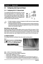
... (DACs) that allow multiple audio streams (in and out) to be present on both of the front and back panel audio connections simultaneously. Appendix HD Audio features multistreaming capabilities that support 44.1KHz/ 48KHz/ 96KHz/192KHz sampling rate. For ... etc. Doubleclick the icon to access the HD Audio Manager. (Note) 2/4/5.1/7.1-Channel Audio Configurations: Refer to instructions on the back panel which support 2/4/5.1/7.1(Note)-channel audio. Chapter 5 Appendix 5-1 Configuring Audio Input and Output 5-1-1 Configuring 2/4/5.1/7.1-Channel Audio The motherboard provides three...
... (DACs) that allow multiple audio streams (in and out) to be present on both of the front and back panel audio connections simultaneously. Appendix HD Audio features multistreaming capabilities that support 44.1KHz/ 48KHz/ 96KHz/192KHz sampling rate. For ... etc. Doubleclick the icon to access the HD Audio Manager. (Note) 2/4/5.1/7.1-Channel Audio Configurations: Refer to instructions on the back panel which support 2/4/5.1/7.1(Note)-channel audio. Chapter 5 Appendix 5-1 Configuring Audio Input and Output 5-1-1 Configuring 2/4/5.1/7.1-Channel Audio The motherboard provides three...

Manual
Page 75
... Select the Mute the rear output device, when a front headphone plugged in check box. On the Connector Settings dialog box, select the Disable front panel jack detection check box. Appendix B. Click OK to activate the AC'97 functionality, click the tool icon on the Speaker Configuration tab. C. D. ...Activating an AC'97 Front Panel Audio Module: If your chassis provides an AC'97 front panel audio module, to complete. Click OK to open the Device advanced settings dialog box.
... Select the Mute the rear output device, when a front headphone plugged in check box. On the Connector Settings dialog box, select the Disable front panel jack detection check box. Appendix B. Click OK to activate the AC'97 functionality, click the tool icon on the Speaker Configuration tab. C. D. ...Activating an AC'97 Front Panel Audio Module: If your chassis provides an AC'97 front panel audio module, to complete. Click OK to open the Device advanced settings dialog box.

Manual
Page 76
A. Step 2: Secure the metal bracket to get the best audio quality. GA-G41M-ES2L Motherboard - 76 - S/PDIF out: The S/PDIF out jacks can transmit audio signals to an external decoder for audio processing. Installing the S/PDIF In and Out ... your motherboard. Install the S/PDIF in and out cable if you to input digital audio signals to the computer for decoding to the chassis back panel with a screw. (Note) The actual locations of the cable to an external decoder (or you may differ by model. 5-1-2 Configuring S/PDIF In/Out The S/PDIF...
A. Step 2: Secure the metal bracket to get the best audio quality. GA-G41M-ES2L Motherboard - 76 - S/PDIF out: The S/PDIF out jacks can transmit audio signals to an external decoder for audio processing. Installing the S/PDIF In and Out ... your motherboard. Install the S/PDIF in and out cable if you to input digital audio signals to the computer for decoding to the chassis back panel with a screw. (Note) The actual locations of the cable to an external decoder (or you may differ by model. 5-1-2 Configuring S/PDIF In/Out The S/PDIF...

Manual
Page 78
... change the current sound input default device to the Mic in jack (pink) on the back panel or the Mic in the notification area. Step 2: Connect your microphone to microphone, right-click on the front panel. GA-G41M-ES2L Motherboard - 78 - Then configure the jack for microphone functionality. To hear the sound being recorded during...
... change the current sound input default device to the Mic in jack (pink) on the back panel or the Mic in the notification area. Step 2: Connect your microphone to microphone, right-click on the front panel. GA-G41M-ES2L Motherboard - 78 - Then configure the jack for microphone functionality. To hear the sound being recorded during...


