Manual
Page 4
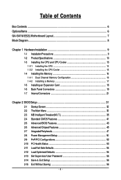
Table of Contents Box Contents ...6 OptionalItems...6 GA-G41M-ES2L Motherboard Layout 7 Block Diagram...8 Chapter 1 Hardware Installation 9 1-1 Installation Precautions 9 1-2 Product Specifications 10 1-3 Installing the CPU and CPU Cooler 13 1-3-1 Installing the CPU 13 1-3-2 Installing the CPU Cooler 15 1-4 Installing the Memory 16 1-4-1 Dual Channel Memory Configuration 16 1-4-2 Installing a Memory 17 1-5 Installing an Expansion Card 18 1-6 Back Panel Connectors 19 1-7 Internal Connectors 21 Chapter...
Table of Contents Box Contents ...6 OptionalItems...6 GA-G41M-ES2L Motherboard Layout 7 Block Diagram...8 Chapter 1 Hardware Installation 9 1-1 Installation Precautions 9 1-2 Product Specifications 10 1-3 Installing the CPU and CPU Cooler 13 1-3-1 Installing the CPU 13 1-3-2 Installing the CPU Cooler 15 1-4 Installing the Memory 16 1-4-1 Dual Channel Memory Configuration 16 1-4-2 Installing a Memory 17 1-5 Installing an Expansion Card 18 1-6 Back Panel Connectors 19 1-7 Internal Connectors 21 Chapter...
Manual
Page 5
Chapter 3 Drivers Installation 57 3-1 Installing Chipset Drivers 57 3-2 Applications Software 58 3-3 Technical Manuals 58 3-4 Contact ...59 3-5 System ...59 3-6 Download Center 60 Chapter 4 Unique Features 61 4-1 Xpress Recovery2 61 4-2 BIOS Update ...
Chapter 3 Drivers Installation 57 3-1 Installing Chipset Drivers 57 3-2 Applications Software 58 3-3 Technical Manuals 58 3-4 Contact ...59 3-5 System ...59 3-6 Download Center 60 Chapter 4 Unique Features 61 4-1 Xpress Recovery2 61 4-2 BIOS Update ...
Manual
Page 9
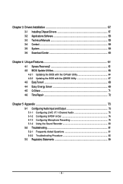
...the motherboard or within an electrostatic shielding container. • Before unplugging the power supply cable from the power outlet before installing or removing the motherboard or other hardware components. • When connecting hardware components to the internal connectors on the computer power during...Number) sticker or warranty sticker provided by your hands dry and first touch a metal object to eliminate static electricity. • Prior to installing the motherboard, please have it on top of an antistatic pad or within the computer casing. • Do not place the computer system ...
...the motherboard or within an electrostatic shielding container. • Before unplugging the power supply cable from the power outlet before installing or removing the motherboard or other hardware components. • When connecting hardware components to the internal connectors on the computer power during...Number) sticker or warranty sticker provided by your hands dry and first touch a metal object to eliminate static electricity. • Prior to installing the motherboard, please have it on top of an antistatic pad or within the computer casing. • Do not place the computer system ...
Manual
Page 11
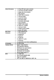
Hardware Installation Internal Connectors 1 x 24-pin ATX main power connector 1 x 4-pin ATX 12V power connector 1 x floppy disk drive connector 1 x IDE connector 4 x SATA ...
Hardware Installation Internal Connectors 1 x 24-pin ATX main power connector 1 x 4-pin ATX 12V power connector 1 x floppy disk drive connector 1 x IDE connector 4 x SATA ...
Manual
Page 12
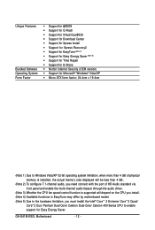
...for @BIOS Support for Q-Flash Support for Virtual DualBIOS Support for Download Center Support for Xpress Install Support for Xpress Recovery2 Support for EasyTune (Note 4) Support for Easy Energy Saver (Note 5) ...install. (Note 4) Available functions in EasyTune may differ by motherboard model. (Note 5) Due to the hardware limitation, you must install the Intel® CoreTM 2 Extreme/ CoreTM 2 Quad/ CoreTM 2 Duo/ Pentium Dual-Core/ Celeron Dual-Core/ Celeron 400 Series CPU to enable support for Easy Energy Saver. GA-G41M-ES2L...
...for @BIOS Support for Q-Flash Support for Virtual DualBIOS Support for Download Center Support for Xpress Install Support for Xpress Recovery2 Support for EasyTune (Note 4) Support for Easy Energy Saver (Note 5) ...install. (Note 4) Available functions in EasyTune may differ by motherboard model. (Note 5) Due to the hardware limitation, you must install the Intel® CoreTM 2 Extreme/ CoreTM 2 Quad/ CoreTM 2 Duo/ Pentium Dual-Core/ Celeron Dual-Core/ Celeron 400 Series CPU to enable support for Easy Energy Saver. GA-G41M-ES2L...

Manual
Page 13
...so according to your hardware specifications including the CPU, graphics card, memory, hard drive, etc. 1-3-1 Installing the CPU A. mended that the motherboard supports the CPU. (Go to GIGABYTE's website for the peripherals. Locate the alignment keys on the motherboard CPU socket and the notches on... the CPU - 13 - 1-3 Installing the CPU and CPU Cooler Read the following guidelines before installing the CPU to prevent hardware damage. &#...
...so according to your hardware specifications including the CPU, graphics card, memory, hard drive, etc. 1-3-1 Installing the CPU A. mended that the motherboard supports the CPU. (Go to GIGABYTE's website for the peripherals. Locate the alignment keys on the motherboard CPU socket and the notches on... the CPU - 13 - 1-3 Installing the CPU and CPU Cooler Read the following guidelines before installing the CPU to prevent hardware damage. &#...
Manual
Page 14
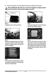
B. GA-G41M-ES2L Motherboard - 14 - CPU Socket Lever Step 1: Completely raise the CPU socket lever. Align the CPU pin one marking (triangle) with the pin one corner of the CPU socket (or you may align the CPU notches with your thumb and index fingers. Step 5: Once the CPU is not installed.) Step 4: Hold the CPU... with the socket alignment keys) and gently insert the CPU into its locked position. Before installing the CPU, make sure to turn off the computer and unplug the power cord from the load plate. (To protect the CPU socket, always replace ...
B. GA-G41M-ES2L Motherboard - 14 - CPU Socket Lever Step 1: Completely raise the CPU socket lever. Align the CPU pin one marking (triangle) with the pin one corner of the CPU socket (or you may align the CPU notches with your thumb and index fingers. Step 5: Once the CPU is not installed.) Step 4: Hold the CPU... with the socket alignment keys) and gently insert the CPU into its locked position. Before installing the CPU, make sure to turn off the computer and unplug the power cord from the load plate. (To protect the CPU socket, always replace ...

Manual
Page 15
... CPU cooler on the motherboard. (The following procedure uses Intel® boxed cooler as the picture above, the installation is to your CPU cooler installation manual for instructions on the motherboard. Use extreme care when removing the CPU cooler because the thermal grease/tape between the CPU cooler and CPU ... complete. Direction of the Arrow Sign on the Male Push Pin Male Push Pin The Top of Female Push Pin Female Push Pin Step 2: Before installing the cooler, note the direction of the arrow sign on the male push pin. (Turning the push pin along the direction of thermal grease on...
... CPU cooler on the motherboard. (The following procedure uses Intel® boxed cooler as the picture above, the installation is to your CPU cooler installation manual for instructions on the motherboard. Use extreme care when removing the CPU cooler because the thermal grease/tape between the CPU cooler and CPU ... complete. Direction of the Arrow Sign on the Male Push Pin Male Push Pin The Top of Female Push Pin Female Push Pin Step 2: Before installing the cooler, note the direction of the arrow sign on the male push pin. (Turning the push pin along the direction of thermal grease on...

Manual
Page 16
... memory: • Make sure that the motherboard supports the memory. GA-G41M-ES2L Motherboard - 16 - After the memory is installed. 2. When enabling Dual Channel mode with two memory modules, it is recommended that memory of the same capacity, brand, speed, and chips be used ..., speed, and chips be used . (Go to GIGABYTE's website for the latest memory support list.) • Always turn off the computer and unplug the power cord from the power outlet before installing the memory in only one DDR2 memory module is installed, the BIOS will double the original memory bandwidth. The...
... memory: • Make sure that the motherboard supports the memory. GA-G41M-ES2L Motherboard - 16 - After the memory is installed. 2. When enabling Dual Channel mode with two memory modules, it is recommended that memory of the same capacity, brand, speed, and chips be used ..., speed, and chips be used . (Go to GIGABYTE's website for the latest memory support list.) • Always turn off the computer and unplug the power cord from the power outlet before installing the memory in only one DDR2 memory module is installed, the BIOS will double the original memory bandwidth. The...

Manual
Page 17
...module is securely inserted. - 17 - Spread the retaining clips at both ends of the memory socket. Hardware Installation DDR2 DIMMs are not compatible to DDR DIMMs. Be sure to install DDR2 DIMMs on the memory and insert it can only fit in one direction. As indicated in the picture .... Place the memory module on the socket. Step 2: The clips at both ends of the socket will snap into the memory socket. 1-4-2 Installing a Memory Before installing a memory module , make sure to turn off the computer and unplug the power cord from the power outlet to prevent damage to correctly...
...module is securely inserted. - 17 - Spread the retaining clips at both ends of the memory socket. Hardware Installation DDR2 DIMMs are not compatible to DDR DIMMs. Be sure to install DDR2 DIMMs on the memory and insert it can only fit in one direction. As indicated in the picture .... Place the memory module on the socket. Step 2: The clips at both ends of the socket will snap into the memory socket. 1-4-2 Installing a Memory Before installing a memory module , make sure to turn off the computer and unplug the power cord from the power outlet to prevent damage to correctly...
Manual
Page 18
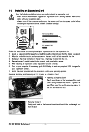
... • Always turn off the computer and unplug the power cord from the power outlet before you begin to correctly install your card. Secure the card's metal bracket to the chassis back panel with the expansion card in the slot and... 4. Example: Installing and Removing a PCI Express x16 Graphics Card: • Installing a Graphics Card: Gently push down on your expansion card(s). 7. GA-G41M-ES2L Motherboard - 18 - After installing all expansion cards, replace the chassis cover(s). 6. 1-5 Installing an Expansion Card Read the following guidelines before installing an expansion card...
... • Always turn off the computer and unplug the power cord from the power outlet before you begin to correctly install your card. Secure the card's metal bracket to the chassis back panel with the expansion card in the slot and... 4. Example: Installing and Removing a PCI Express x16 Graphics Card: • Installing a Graphics Card: Gently push down on your expansion card(s). 7. GA-G41M-ES2L Motherboard - 18 - After installing all expansion cards, replace the chassis cover(s). 6. 1-5 Installing an Expansion Card Read the following guidelines before installing an expansion card...
Manual
Page 19
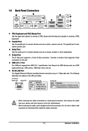
... flash drive and etc. The parallel port is occurring • When removing the cable connected to connect devices such as a printer, scanner and etc. Hardware Installation 1-6 Back Panel Connectors PS/2 Keyboard and PS/2 Mouse Port Use the upper port (green) to connect a PS/2 mouse and the lower port (purple) to 1 Gbps...
... flash drive and etc. The parallel port is occurring • When removing the cable connected to connect devices such as a printer, scanner and etc. Hardware Installation 1-6 Back Panel Connectors PS/2 Keyboard and PS/2 Mouse Port Use the upper port (green) to connect a PS/2 mouse and the lower port (purple) to 1 Gbps...
Manual
Page 21
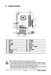
... the following guidelines before turning on the motherboard. - 21 - Unplug the power cord from the power outlet to prevent damage to the devices. • After installing the device and before connecting external devices: • First make sure the device cable has been securely attached to the connector on the computer, make... sure your devices are compliant with the connectors you wish to connect. • Before installing the devices, be sure to turn off the devices and your computer. Hardware...
... the following guidelines before turning on the motherboard. - 21 - Unplug the power cord from the power outlet to prevent damage to the devices. • After installing the device and before connecting external devices: • First make sure the device cable has been securely attached to the connector on the computer, make... sure your devices are compliant with the connectors you wish to connect. • Before installing the devices, be sure to turn off the devices and your computer. Hardware...

Manual
Page 22
...3V -12V GND PS_ON(soft On/Off) GND GND GND -5V +5V +5V +5V (Only for 2x12-pinATX) GND (Only for 2x12-pin ATX) GA-G41M-ES2L Motherboard - 22 - Before connecting the power connector, first make sure the power supply is compatible with power supplies with 2x10 power connectors. 1/2) ATX_12V/ATX (... 2x12 Main Power Connector) With the use of the power connector, the power supply can supply enough stable power to all devices are properly installed. Connect the power supply cable to an unstable or unbootable system. • The main power connector is turned off and all the components ...
...3V -12V GND PS_ON(soft On/Off) GND GND GND -5V +5V +5V +5V (Only for 2x12-pinATX) GND (Only for 2x12-pin ATX) GA-G41M-ES2L Motherboard - 22 - Before connecting the power connector, first make sure the power supply is compatible with power supplies with 2x10 power connectors. 1/2) ATX_12V/ATX (... 2x12 Main Power Connector) With the use of the power connector, the power supply can supply enough stable power to all devices are properly installed. Connect the power supply cable to an unstable or unbootable system. • The main power connector is turned off and all the components ...

Manual
Page 23
.... The motherboard supports CPU fan speed control, which requires the use of different color. 33 1 34 2 - 23 - Hardware Installation The pin 1 of the cable is the ground wire). When connecting a fan cable, be installed inside the chassis. 1 CPU_FAN CPU_FAN : Pin No. 1 2 3 4 Definition GND +12V / Speed Control Sense Speed Control 1 SYS_FAN SYS_FAN : Pin...
.... The motherboard supports CPU fan speed control, which requires the use of different color. 33 1 34 2 - 23 - Hardware Installation The pin 1 of the cable is the ground wire). When connecting a fan cable, be installed inside the chassis. 1 CPU_FAN CPU_FAN : Pin No. 1 2 3 4 Definition GND +12V / Speed Control Sense Speed Control 1 SYS_FAN SYS_FAN : Pin...
Manual
Page 25
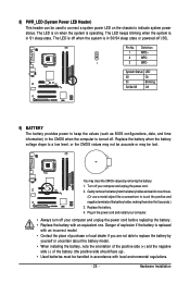
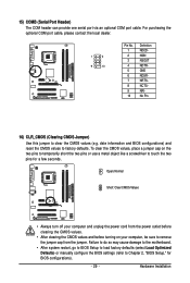
...like a screwdriver to touch the positive and negative terminals of the battery (the positive side should face up). • Used batteries must be lost. Hardware Installation Pin No. Definition 1 MPD+ 2 MPD- 1 3 MPD- System Status LED S0 On S1 Blinking S3/S4/S5 Off 9) BATTERY The battery provides... or the CMOS values may not be accurate or may clear the CMOS values by yourself or uncertain about the battery model. • When installing the battery, note the orientation of the positive side (+) and the negative side (-) of the battery holder, making them short for one ....
...like a screwdriver to touch the positive and negative terminals of the battery (the positive side should face up). • Used batteries must be lost. Hardware Installation Pin No. Definition 1 MPD+ 2 MPD- 1 3 MPD- System Status LED S0 On S1 Blinking S3/S4/S5 Off 9) BATTERY The battery provides... or the CMOS values may not be accurate or may clear the CMOS values by yourself or uncertain about the battery model. • When installing the battery, note the orientation of the positive side (+) and the negative side (-) of the battery holder, making them short for one ....

Manual
Page 27
... back panel audio connections simultaneously. For information about connecting the front panel audio module that has separated connectors on both of the motherboard header. Hardware Installation Incorrect connection between the module connector and the motherboard header will be present on each wire instead of a single plug. If your chassis provides an...
... back panel audio connections simultaneously. For information about connecting the front panel audio module that has separated connectors on both of the motherboard header. Hardware Installation Incorrect connection between the module connector and the motherboard header will be present on each wire instead of a single plug. If your chassis provides an...
Manual
Page 28
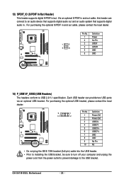
...) F_USB1/F_USB2 (USB Headers) The headers conform to an audio device that supports digital audio out and an audio system that supports digital audio in. GA-G41M-ES2L Motherboard - 28 - Each USB header can connect to USB 2.0/1.1 specification. 13) SPDIF_IO (S/PDIF In/Out Header) This header supports digital S/PDIF in and ...7 GND 8 GND 9 No Pin 10 NC • Do not plug the IEEE 1394 bracket (2x5-pin) cable into the USB header. • Prior to installing the USB bracket, be sure to turn off your computer and unplug the power cord from the power outlet to prevent damage to the USB...
...) F_USB1/F_USB2 (USB Headers) The headers conform to an audio device that supports digital audio out and an audio system that supports digital audio in. GA-G41M-ES2L Motherboard - 28 - Each USB header can connect to USB 2.0/1.1 specification. 13) SPDIF_IO (S/PDIF In/Out Header) This header supports digital S/PDIF in and ...7 GND 8 GND 9 No Pin 10 NC • Do not plug the IEEE 1394 bracket (2x5-pin) cable into the USB header. • Prior to installing the USB bracket, be sure to turn off your computer and unplug the power cord from the power outlet to prevent damage to the USB...
Manual
Page 29
... the two pins for BIOS configurations). - 29 - date information and BIOS configurations) and reset the CMOS values to Chapter 2, "BIOS Setup," for a few seconds. Hardware Installation 15) COMB (Serial Port Header) The COM header can provide one serial port via an optional COM port cable.
... the two pins for BIOS configurations). - 29 - date information and BIOS configurations) and reset the CMOS values to Chapter 2, "BIOS Setup," for a few seconds. Hardware Installation 15) COMB (Serial Port Header) The COM header can provide one serial port via an optional COM port cable.
Manual
Page 35
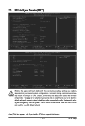
...: Save F6: Fail-Safe Defaults ESC: Exit F1: General Help F7: Optimized Defaults Whether the system will work stably with the overclock/overvoltage settings you install a CPU that supports this feature. - 35 - Incorrectly doing overclock/overvoltage may result in damage to default values.) (Note) This item appears only if you made...
...: Save F6: Fail-Safe Defaults ESC: Exit F1: General Help F7: Optimized Defaults Whether the system will work stably with the overclock/overvoltage settings you install a CPU that supports this feature. - 35 - Incorrectly doing overclock/overvoltage may result in damage to default values.) (Note) This item appears only if you made...


