
Manual
Page 1
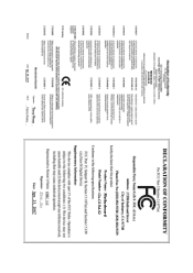
GA-G33M-DS2R/ GA-G33M-S2 LGA775 socket motherboard for Intel® CoreTM processor family/ Intel® Pentium® processor family/Intel® Celeron® processor family User's Manual Rev. 1003 12ME-G33MD2R-1003R * The WEEE marking on the product indicates this product must not be disposed of with user's other household waste and must be handed over to a designated collection point for the recycling of waste electrical and electronic equipment!! * The WEEE marking applies only in European Union's member states.
GA-G33M-DS2R/ GA-G33M-S2 LGA775 socket motherboard for Intel® CoreTM processor family/ Intel® Pentium® processor family/Intel® Celeron® processor family User's Manual Rev. 1003 12ME-G33MD2R-1003R * The WEEE marking on the product indicates this product must not be disposed of with user's other household waste and must be handed over to a designated collection point for the recycling of waste electrical and electronic equipment!! * The WEEE marking applies only in European Union's member states.
Manual
Page 3
Motherboard GA-G33M-S2 Apr. 25, 2007 Motherboard GA-G33M-S2 Apr. 25, 2007
Motherboard GA-G33M-S2 Apr. 25, 2007 Motherboard GA-G33M-S2 Apr. 25, 2007

Manual
Page 5
Table of Contents OptionalItems ...7 Box Contents ...7 GA-G33M-DS2R/S2 Motherboard Layout 8 Block Diagram ...9 Chapter 1 Hardware Installation 11 1-1 Installation Precautions 11 1-2 Product Specifications 12 1-3 Installing the CPU and CPU Cooler 15 1-3-1 Installing the CPU 15 1-3-2 ...
Table of Contents OptionalItems ...7 Box Contents ...7 GA-G33M-DS2R/S2 Motherboard Layout 8 Block Diagram ...9 Chapter 1 Hardware Installation 11 1-1 Installation Precautions 11 1-2 Product Specifications 12 1-3 Installing the CPU and CPU Cooler 15 1-3-1 Installing the CPU 15 1-3-2 ...
Manual
Page 7
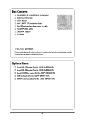
... GA-G33M-DS2R or GA-G33M-S2 motherboard Motherboard driver disk User's Manual Intel® LGA775 CPU Installation Guide One IDE cable and one floppy disk drive cable Tow SATA 3Gb/s cables One SATA bracket I/O Shield Only for reference only and the actual items shall depend on product package you obtain. The box contents are for GA-G33M-DS2R...
... GA-G33M-DS2R or GA-G33M-S2 motherboard Motherboard driver disk User's Manual Intel® LGA775 CPU Installation Guide One IDE cable and one floppy disk drive cable Tow SATA 3Gb/s cables One SATA bracket I/O Shield Only for reference only and the actual items shall depend on product package you obtain. The box contents are for GA-G33M-DS2R...
Manual
Page 8
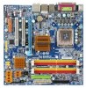
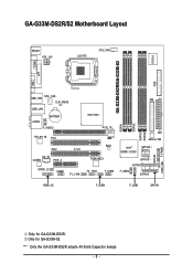
GA-G33M-DS2R/S2 Motherboard Layout KB_MS ATX_12V LGA775 CPU_FAN IT8718 FDD GA-G33M-DS2R/GA-G33M-S2 DDRII1 COMA LPT VGA USB_1394 SYS _FAN CLR_CMOS USB_LAN AUDIO BATTERY F_AUDIO RTL8111B PCI1 PCI2 CI CD_IN CODEC PCIE_4 SPDIF_IO COMB F1_1394 IDE Intel® ... F_USB3 ATX JMicron 368 Intel® ICH9R /ICH9 SATAII2 SATAII3 SATAII4 F_USB2 SATAII5 HDMI_AC F_USB4 F_USB1 SATAII1 DDRII2 DDRII3 DDRII4 SATAII0 PWR_LED F_PANEL Only for GA-G33M-S2. "*" Only the GA-G33M-DS2R adopts All-Solid Capacitor design. - 8 - Only for...
GA-G33M-DS2R/S2 Motherboard Layout KB_MS ATX_12V LGA775 CPU_FAN IT8718 FDD GA-G33M-DS2R/GA-G33M-S2 DDRII1 COMA LPT VGA USB_1394 SYS _FAN CLR_CMOS USB_LAN AUDIO BATTERY F_AUDIO RTL8111B PCI1 PCI2 CI CD_IN CODEC PCIE_4 SPDIF_IO COMB F1_1394 IDE Intel® ... F_USB3 ATX JMicron 368 Intel® ICH9R /ICH9 SATAII2 SATAII3 SATAII4 F_USB2 SATAII5 HDMI_AC F_USB4 F_USB1 SATAII1 DDRII2 DDRII3 DDRII4 SATAII0 PWR_LED F_PANEL Only for GA-G33M-S2. "*" Only the GA-G33M-DS2R adopts All-Solid Capacitor design. - 8 - Only for...

Manual
Page 9
.../Subwoofer Speaker Out Side Speaker Out MIC Line-Out Line-In SPDIF In SPDIF Out 2 PCI PCI CLK(33 MHz) PS/2 KB/Mouse Only for GA-G33M-S2. - 9 - Only for GA-G33M-DS2R.
.../Subwoofer Speaker Out Side Speaker Out MIC Line-Out Line-In SPDIF In SPDIF Out 2 PCI PCI CLK(33 MHz) PS/2 KB/Mouse Only for GA-G33M-S2. - 9 - Only for GA-G33M-DS2R.
Manual
Page 12
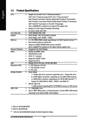
"*" Only the GA-G33M-DS2R adopts All-Solid Capacitor design. GA-G33M-DS2R/S2 Motherboard - 12 - English 1-2 Product Specifications CPU Front Side Bus Chipset Memory Onboard Graphics Audio LAN Expansion Slots Storage Interface IEEE 1394 Š Support for ... sockets supporting up to 8 GB of system memory (Note 1) Š Dual channel memory architecture Š Support for DDR2 800/667 MHz memory modules (Go to GIGABYTE's website for the latest memory support list.) Š Integrated in the North Bridge Š Realtek ALC889A codec Š High Definition Audio Š 2/4/5.1/7.1-channel Š...
"*" Only the GA-G33M-DS2R adopts All-Solid Capacitor design. GA-G33M-DS2R/S2 Motherboard - 12 - English 1-2 Product Specifications CPU Front Side Bus Chipset Memory Onboard Graphics Audio LAN Expansion Slots Storage Interface IEEE 1394 Š Support for ... sockets supporting up to 8 GB of system memory (Note 1) Š Dual channel memory architecture Š Support for DDR2 800/667 MHz memory modules (Go to GIGABYTE's website for the latest memory support list.) Š Integrated in the North Bridge Š Realtek ALC889A codec Š High Definition Audio Š 2/4/5.1/7.1-channel Š...
Manual
Page 13
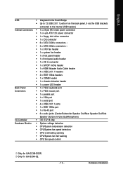
Hardware Installation Only for GA-G33M-DS2R. English USB Š Integrated in the South Bridge Š Up to 12 USB 2.0/1.1 ports (4 on the back panel, 8 via the USB brackets connected to the ... temperature detection Š CPU/System fan speed detection Š CPU overheating warning Š CPU/System fan fail warning Š CPU fan speed control Only for GA-G33M-S2. - 13 -
Hardware Installation Only for GA-G33M-DS2R. English USB Š Integrated in the South Bridge Š Up to 12 USB 2.0/1.1 ports (4 on the back panel, 8 via the USB brackets connected to the ... temperature detection Š CPU/System fan speed detection Š CPU overheating warning Š CPU/System fan fail warning Š CPU fan speed control Only for GA-G33M-S2. - 13 -

Manual
Page 14
... 3) Available functions in Easytune may differ by motherboard model. (Note 4) Due to chipset limitation, Intel ICH9R RAID driver does not support Windows 2000 operating system. GA-G33M-DS2R/S2 Motherboard - 14 -
... 3) Available functions in Easytune may differ by motherboard model. (Note 4) Due to chipset limitation, Intel ICH9R RAID driver does not support Windows 2000 operating system. GA-G33M-DS2R/S2 Motherboard - 14 -

Manual
Page 16
Step 2: Remove the protective socket cover. GA-G33M-DS2R/S2 Motherboard - 16 - Step 5: Once the CPU is properly inserted, replace the load plate and push the CPU socket lever back into the motherboard CPU socket. ...
Step 2: Remove the protective socket cover. GA-G33M-DS2R/S2 Motherboard - 16 - Step 5: Once the CPU is properly inserted, replace the load plate and push the CPU socket lever back into the motherboard CPU socket. ...

Manual
Page 18
... the memory is recommended that memory of the same capacity, brand, speed, and chips be used . (Go to GIGABYTE's website for optimum performance. Dual Channel mode cannot be installed in Dual Channel mode. 1. GA-G33M-DS2R/S2 Motherboard - 18 - DS/SS DS/SS (SS=Single-Sided, DS=Double-Sided, "- -"=No Memory) DDRII1 DDRII2 DDRII3 DDRII4...
... the memory is recommended that memory of the same capacity, brand, speed, and chips be used . (Go to GIGABYTE's website for optimum performance. Dual Channel mode cannot be installed in Dual Channel mode. 1. GA-G33M-DS2R/S2 Motherboard - 18 - DS/SS DS/SS (SS=Single-Sided, DS=Double-Sided, "- -"=No Memory) DDRII1 DDRII2 DDRII3 DDRII4...
Manual
Page 20
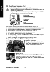
... PCI Express x16 slot. Make sure the small white-drawable bar securely locks the graphics card. • Removing the Card: Pull out the small white- GA-G33M-DS2R/S2 Motherboard - 20 - PCI Express x16 Slot PCI Express x4 Slot PCI Slot Follow the steps below to correctly install your expansion card(s). 7. Carefully read the...
... PCI Express x16 slot. Make sure the small white-drawable bar securely locks the graphics card. • Removing the Card: Pull out the small white- GA-G33M-DS2R/S2 Motherboard - 20 - PCI Express x16 Slot PCI Express x4 Slot PCI Slot Follow the steps below to correctly install your expansion card(s). 7. Carefully read the...

Manual
Page 22
... (Pink) The default Mic in devices such as an optical drive, walkman, etc. Microphones must be used to connect front speakers in a 7.1-channel audio configuration. GA-G33M-DS2R/S2 Motherboard - 22 - Refer to the instructions on setting up a 2/4/5.1/ 7.1-channel audio configuration in a 5.1/7.1-channel audio configuration. In addition to the default speakers settings, the ~ audio...
... (Pink) The default Mic in devices such as an optical drive, walkman, etc. Microphones must be used to connect front speakers in a 7.1-channel audio configuration. GA-G33M-DS2R/S2 Motherboard - 22 - Refer to the instructions on setting up a 2/4/5.1/ 7.1-channel audio configuration in a 5.1/7.1-channel audio configuration. In addition to the default speakers settings, the ~ audio...

Manual
Page 24
... 3.3V -12V GND PS_ON(soft On/Off) GND GND GND -5V +5V +5V +5V (Only for 2x12-pin ATX) GND (Only for 2x12-pin ATX) GA-G33M-DS2R/S2 Motherboard - 24 - Before connecting the power connector, first make sure the power supply is compatible with power supplies with 2x10 power connectors. If a power supply...
... 3.3V -12V GND PS_ON(soft On/Off) GND GND GND -5V +5V +5V +5V (Only for 2x12-pin ATX) GND (Only for 2x12-pin ATX) GA-G33M-DS2R/S2 Motherboard - 24 - Before connecting the power connector, first make sure the power supply is compatible with power supplies with 2x10 power connectors. If a power supply...
Manual
Page 26
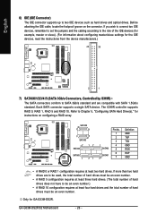
... drives must be an even number.) • A RAID 10 configuration requires at least two hard drives. GA-G33M-DS2R/S2 Motherboard - 26 - English 6) IDE (IDE Connector) The IDE connector supports up to Chapter 5, "Configuring SATA Hard Drive(s)," for GA-G33M-DS2R. If more than two hard drives are compatible with SATA 1.5Gb/s standard. Each SATA connector supports...
... drives must be an even number.) • A RAID 10 configuration requires at least two hard drives. GA-G33M-DS2R/S2 Motherboard - 26 - English 6) IDE (IDE Connector) The IDE connector supports up to Chapter 5, "Configuring SATA Hard Drive(s)," for GA-G33M-DS2R. If more than two hard drives are compatible with SATA 1.5Gb/s standard. Each SATA connector supports...
Manual
Page 27
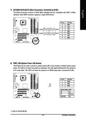
The LED is in S1 sleep state. System Status LED S0 On S1 Blinking S3/S4/S5 Off Only for GA-G33M-S2. - 27 - The LED keeps blinking when the system is in S3/S4 sleep state or powered off when the system is off (S5). Each SATA ...
The LED is in S1 sleep state. System Status LED S0 On S1 Blinking S3/S4/S5 Off Only for GA-G33M-S2. - 27 - The LED keeps blinking when the system is in S3/S4 sleep state or powered off when the system is off (S5). Each SATA ...

Manual
Page 28
... the values (such as BIOS configurations, date, and time information) in the CMOS when the computer is replaced with local environmental regulations. Replace the battery. 4. GA-G33M-DS2R/S2 Motherboard - 28 - Gently remove the battery from the battery holder and wait for 5 seconds.) 3.
... the values (such as BIOS configurations, date, and time information) in the CMOS when the computer is replaced with local environmental regulations. Replace the battery. 4. GA-G33M-DS2R/S2 Motherboard - 28 - Gently remove the battery from the battery holder and wait for 5 seconds.) 3.

Manual
Page 30
...) F_AUDIO (Front Panel Audio Header) The front panel audio header supports Intel High Definition audio (HD) and AC'97 audio. Definition 1 CD-L 1 2 GND 3 GND 4 CD-R GA-G33M-DS2R/S2 Motherboard - 30 - Definition 1 MIC 2 GND 3 MIC Power 4 NC 5 Line Out (R) 6 NC 7 NC 8 No Pin 9 Line Out (L) 10 NC • The front panel audio header supports...
...) F_AUDIO (Front Panel Audio Header) The front panel audio header supports Intel High Definition audio (HD) and AC'97 audio. Definition 1 CD-L 1 2 GND 3 GND 4 CD-R GA-G33M-DS2R/S2 Motherboard - 30 - Definition 1 MIC 2 GND 3 MIC Power 4 NC 5 Line Out (R) 6 NC 7 NC 8 No Pin 9 Line Out (L) 10 NC • The front panel audio header supports...

Manual
Page 32
USB DY- Pin No. Ensure that the cable is securely connected. For purchasing the optional IEEE 1394a bracket, please contact the local dealer. GA-G33M-DS2R/S2 Motherboard - 32 - For purchasing the optional USB bracket, please contact the local dealer. 9 19 1 10 9 10 9 10 2 10 2 F_USB4 F_USB3 Pin No. 1 2 3 4 5 6 7 8 9 10 2 12 1 F_USB2 ...
USB DY- Pin No. Ensure that the cable is securely connected. For purchasing the optional IEEE 1394a bracket, please contact the local dealer. GA-G33M-DS2R/S2 Motherboard - 32 - For purchasing the optional USB bracket, please contact the local dealer. 9 19 1 10 9 10 9 10 2 10 2 F_USB4 F_USB3 Pin No. 1 2 3 4 5 6 7 8 9 10 2 12 1 F_USB2 ...

Manual
Page 34
... BIOS Setup to load factory defaults (select Load Optimized Defaults) or manually configure the BIOS settings (refer to touch the two pins for BIOS configurations). GA-G33M-DS2R/S2 Motherboard - 34 - date information and BIOS configurations) and reset the CMOS values to clear the CMOS values (e.g.
... BIOS Setup to load factory defaults (select Load Optimized Defaults) or manually configure the BIOS settings (refer to touch the two pins for BIOS configurations). GA-G33M-DS2R/S2 Motherboard - 34 - date information and BIOS configurations) and reset the CMOS values to clear the CMOS values (e.g.


