
Manual
Page 1
GA-G33M-DS2R/ GA-G33M-S2 LGA775 socket motherboard for Intel® CoreTM processor family/ Intel® Pentium® processor family/Intel® Celeron® processor family User's Manual Rev. 1003 12ME-G33MD2R-1003R * The WEEE marking on the product indicates this product must not be disposed of with user's other household waste and must be handed over to a designated collection point for the recycling of waste electrical and electronic equipment!! * The WEEE marking applies only in European Union's member states.
GA-G33M-DS2R/ GA-G33M-S2 LGA775 socket motherboard for Intel® CoreTM processor family/ Intel® Pentium® processor family/Intel® Celeron® processor family User's Manual Rev. 1003 12ME-G33MD2R-1003R * The WEEE marking on the product indicates this product must not be disposed of with user's other household waste and must be handed over to a designated collection point for the recycling of waste electrical and electronic equipment!! * The WEEE marking applies only in European Union's member states.

Manual
Page 2
Motherboard GA-G33M-DS2R Apr. 17, 2007 Motherboard GA-G33M-DS2R Apr. 17, 2007
Motherboard GA-G33M-DS2R Apr. 17, 2007 Motherboard GA-G33M-DS2R Apr. 17, 2007
Manual
Page 3
Motherboard GA-G33M-S2 Apr. 25, 2007 Motherboard GA-G33M-S2 Apr. 25, 2007
Motherboard GA-G33M-S2 Apr. 25, 2007 Motherboard GA-G33M-S2 Apr. 25, 2007

Manual
Page 4
...: X.X." by GIGA-BYTE TECHNOLOGY CO., LTD as the exclusive global distributor of GIGABYTE branded motherboards. GIGABYTE UNITED INC. Documentation Classifications In order to GIGABYTE UNITED INC. Check your motherboard looks like this manual may be made by copyright laws and is protected by GIGABYTE without GIGABYTE's prior written permission. Copyright © 2007 GIGA-BYTE TECHNOLOGY CO., LTD...
...: X.X." by GIGA-BYTE TECHNOLOGY CO., LTD as the exclusive global distributor of GIGABYTE branded motherboards. GIGABYTE UNITED INC. Documentation Classifications In order to GIGABYTE UNITED INC. Check your motherboard looks like this manual may be made by copyright laws and is protected by GIGABYTE without GIGABYTE's prior written permission. Copyright © 2007 GIGA-BYTE TECHNOLOGY CO., LTD...

Manual
Page 5
Table of Contents OptionalItems ...7 Box Contents ...7 GA-G33M-DS2R/S2 Motherboard Layout 8 Block Diagram ...9 Chapter 1 Hardware Installation 11 1-1 Installation Precautions 11 1-2 Product Specifications 12 1-3 Installing the CPU and CPU Cooler 15 1-3-1 Installing the CPU 15 1-3-2 Installing ...
Table of Contents OptionalItems ...7 Box Contents ...7 GA-G33M-DS2R/S2 Motherboard Layout 8 Block Diagram ...9 Chapter 1 Hardware Installation 11 1-1 Installation Precautions 11 1-2 Product Specifications 12 1-3 Installing the CPU and CPU Cooler 15 1-3-1 Installing the CPU 15 1-3-2 Installing ...
Manual
Page 7
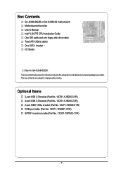
The box contents are for GA-G33M-DS2R. Optional Items 2-port USB 2.0 bracket (Part No. 12CR1-1UB030-51/R) 4-port USB 2.0 bracket (Part No. 12CR1-1UB030-21/R) 2-port IEEE 1394a bracket (Part No. 12CF1-...-1CM001-31/R) S/PDIF in and out cable (Part No. 12CR1-1SPINO-11/R) - 7 - The box contents above are subject to change without notice. Box Contents GA-G33M-DS2R or GA-G33M-S2 motherboard Motherboard driver disk User's Manual Intel® LGA775 CPU Installation Guide One IDE cable and one floppy disk drive cable Tow SATA 3Gb/s cables One...
The box contents are for GA-G33M-DS2R. Optional Items 2-port USB 2.0 bracket (Part No. 12CR1-1UB030-51/R) 4-port USB 2.0 bracket (Part No. 12CR1-1UB030-21/R) 2-port IEEE 1394a bracket (Part No. 12CF1-...-1CM001-31/R) S/PDIF in and out cable (Part No. 12CR1-1SPINO-11/R) - 7 - The box contents above are subject to change without notice. Box Contents GA-G33M-DS2R or GA-G33M-S2 motherboard Motherboard driver disk User's Manual Intel® LGA775 CPU Installation Guide One IDE cable and one floppy disk drive cable Tow SATA 3Gb/s cables One...
Manual
Page 8
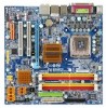
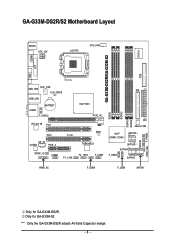
"*" Only the GA-G33M-DS2R adopts All-Solid Capacitor design. - 8 - Only for GA-G33M-DS2R. GA-G33M-DS2R/S2 Motherboard Layout KB_MS ATX_12V LGA775 CPU_FAN IT8718 FDD GA-G33M-DS2R/GA-G33M-S2 DDRII1 COMA LPT VGA USB_1394 SYS _FAN CLR_CMOS USB_LAN AUDIO BATTERY F_AUDIO RTL8111B PCI1 PCI2 CI CD_IN CODEC PCIE_4 SPDIF_IO COMB F1_1394 IDE Intel&#... F_USB3 ATX JMicron 368 Intel® ICH9R /ICH9 SATAII2 SATAII3 SATAII4 F_USB2 SATAII5 HDMI_AC F_USB4 F_USB1 SATAII1 DDRII2 DDRII3 DDRII4 SATAII0 PWR_LED F_PANEL Only for GA-G33M-S2.
"*" Only the GA-G33M-DS2R adopts All-Solid Capacitor design. - 8 - Only for GA-G33M-DS2R. GA-G33M-DS2R/S2 Motherboard Layout KB_MS ATX_12V LGA775 CPU_FAN IT8718 FDD GA-G33M-DS2R/GA-G33M-S2 DDRII1 COMA LPT VGA USB_1394 SYS _FAN CLR_CMOS USB_LAN AUDIO BATTERY F_AUDIO RTL8111B PCI1 PCI2 CI CD_IN CODEC PCIE_4 SPDIF_IO COMB F1_1394 IDE Intel&#... F_USB3 ATX JMicron 368 Intel® ICH9R /ICH9 SATAII2 SATAII3 SATAII4 F_USB2 SATAII5 HDMI_AC F_USB4 F_USB1 SATAII1 DDRII2 DDRII3 DDRII4 SATAII0 PWR_LED F_PANEL Only for GA-G33M-S2.

Manual
Page 11
...not have an ESD wrist strap, keep your hands dry and first touch a metal object to eliminate static electricity. • Prior to installing the motherboard, please have it on top of an antistatic pad or within the computer casing. • Do not place the computer system on an uneven ... damage to system components as well as physical harm to the user. • If you are connected tightly and securely. • When handling the motherboard, avoid touching any installation steps or have a problem related to the use of your hardware components are connected. • To prevent damage to the ...
...not have an ESD wrist strap, keep your hands dry and first touch a metal object to eliminate static electricity. • Prior to installing the motherboard, please have it on top of an antistatic pad or within the computer casing. • Do not place the computer system on an uneven ... damage to system components as well as physical harm to the user. • If you are connected tightly and securely. • When handling the motherboard, avoid touching any installation steps or have a problem related to the use of your hardware components are connected. • To prevent damage to the ...
Manual
Page 12
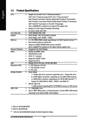
...368 chip: - 1 x IDE connector supporting ATA-133/100/66/33 and up to 2 IDE devices Š T.I. "*" Only the GA-G33M-DS2R adopts All-Solid Capacitor design. GA-G33M-DS2R/S2 Motherboard - 12 - TSB43AB23 chip Š Up to 3 IEEE 1394a ports (1 on the back panel, 2 via the IEEE 1394 bracket ...174; 4 processor Extreme Edition/Intel® Pentium® 4 processor/ Intel® Celeron® D processor in the LGA 775 package (Go to GIGABYTE's website for the latest CPU support list.) Š Support for Intel® Hyper-Threading Technology Š L2 cache varies with CPU Š 1333...
...368 chip: - 1 x IDE connector supporting ATA-133/100/66/33 and up to 2 IDE devices Š T.I. "*" Only the GA-G33M-DS2R adopts All-Solid Capacitor design. GA-G33M-DS2R/S2 Motherboard - 12 - TSB43AB23 chip Š Up to 3 IEEE 1394a ports (1 on the back panel, 2 via the IEEE 1394 bracket ...174; 4 processor Extreme Edition/Intel® Pentium® 4 processor/ Intel® Celeron® D processor in the LGA 775 package (Go to GIGABYTE's website for the latest CPU support list.) Š Support for Intel® Hyper-Threading Technology Š L2 cache varies with CPU Š 1333...

Manual
Page 14
GA-G33M-DS2R/S2 Motherboard - 14 - English BIOS Unique Features Bundled Software Operating System Form Factor Š 1 x 8 Mbit flash Š Use of licensed AWARD BIOS Š PnP 1.0a, DMI 2.0, SM ... SATA connectors for AHCI mode. (Refer to Chapter 2, "BIOS Setup," "Integrated Peripherals," for details on enabling AHCI.) (Note 3) Available functions in Easytune may differ by motherboard model. (Note 4) Due to chipset limitation, Intel ICH9R RAID driver does not support Windows 2000 operating system.
GA-G33M-DS2R/S2 Motherboard - 14 - English BIOS Unique Features Bundled Software Operating System Form Factor Š 1 x 8 Mbit flash Š Use of licensed AWARD BIOS Š PnP 1.0a, DMI 2.0, SM ... SATA connectors for AHCI mode. (Refer to Chapter 2, "BIOS Setup," "Integrated Peripherals," for details on enabling AHCI.) (Note 3) Available functions in Easytune may differ by motherboard model. (Note 4) Due to chipset limitation, Intel ICH9R RAID driver does not support Windows 2000 operating system.

Manual
Page 15
...optimized for HT Technology • A BIOS that supports HT Technology and has it does not meet the standard requirements for the peripherals. mended that the motherboard supports the CPU. (Go to GIGABYTE's website for the latest CPU support list.) • Always turn on the CPU. Locate the alignment keys on the... motherboard CPU socket and the notches on the computer if the CPU cooler is not recom- Notch Triangle Pin One Marking on the CPU Hardware ...
...optimized for HT Technology • A BIOS that supports HT Technology and has it does not meet the standard requirements for the peripherals. mended that the motherboard supports the CPU. (Go to GIGABYTE's website for the latest CPU support list.) • Always turn on the CPU. Locate the alignment keys on the... motherboard CPU socket and the notches on the computer if the CPU cooler is not recom- Notch Triangle Pin One Marking on the CPU Hardware ...

Manual
Page 16
... sure to turn off the computer and unplug the power cord from the power outlet to prevent damage to correctly install the CPU into the motherboard CPU socket. Step 3: Lift the metal load plate on the CPU socket. Step 2: Remove the protective socket cover. English B. Step 5: ...CPU socket lever back into position. Step 4: Hold the CPU with the socket alignment keys) and gently insert the CPU into its locked position. GA-G33M-DS2R/S2 Motherboard - 16 - CPU Socket Lever Step 1: Completely raise the CPU socket lever. Align the CPU pin one marking (triangle) with the pin ...
... sure to turn off the computer and unplug the power cord from the power outlet to prevent damage to correctly install the CPU into the motherboard CPU socket. Step 3: Lift the metal load plate on the CPU socket. Step 2: Remove the protective socket cover. English B. Step 5: ...CPU socket lever back into position. Step 4: Hold the CPU with the socket alignment keys) and gently insert the CPU into its locked position. GA-G33M-DS2R/S2 Motherboard - 16 - CPU Socket Lever Step 1: Completely raise the CPU socket lever. Align the CPU pin one marking (triangle) with the pin ...

Manual
Page 17
... the installed CPU. Check that the Male and Female push pins are joined closely. (Refer to the CPU fan header (CPU_FAN) on the motherboard. Inadequately removing the CPU cooler may adhere to install.) Step 3: Place the cooler atop the CPU, aligning the four push pins through the ...the example cooler.) Step 1: Apply an even and thin layer of thermal grease on the surface of the motherboard. Step 4: You should hear a "click" when pushing down on the motherboard. Hardware Installation Use extreme care when removing the CPU cooler because the thermal grease/tape between the CPU ...
... the installed CPU. Check that the Male and Female push pins are joined closely. (Refer to the CPU fan header (CPU_FAN) on the motherboard. Inadequately removing the CPU cooler may adhere to install.) Step 3: Place the cooler atop the CPU, aligning the four push pins through the ...the example cooler.) Step 1: Apply an even and thin layer of thermal grease on the surface of the motherboard. Step 4: You should hear a "click" when pushing down on the motherboard. Hardware Installation Use extreme care when removing the CPU cooler because the thermal grease/tape between the CPU ...

Manual
Page 18
... Technology offers greater flexibility to upgrade by allowing different memory sizes to insert the memory, switch the direction. 1-4-1 Dual Channel Memory Configuration This motherboard provides four DDR2 memory sockets and supports Dual Channel Technology. DS/SS - - Dual Channel mode cannot be used and installed in the same...a message which says memory is installed, the BIOS will appear during the POST. DS/SS - - A memory module can be used . (Go to GIGABYTE's website for optimum performance. Four Modules DS/SS DS/SS DS/SS DDRII4 - GA-G33M-DS2R/S2 Motherboard - 18 -
... Technology offers greater flexibility to upgrade by allowing different memory sizes to insert the memory, switch the direction. 1-4-1 Dual Channel Memory Configuration This motherboard provides four DDR2 memory sockets and supports Dual Channel Technology. DS/SS - - Dual Channel mode cannot be used and installed in the same...a message which says memory is installed, the BIOS will appear during the POST. DS/SS - - A memory module can be used . (Go to GIGABYTE's website for optimum performance. Four Modules DS/SS DS/SS DS/SS DDRII4 - GA-G33M-DS2R/S2 Motherboard - 18 -

Manual
Page 19
... , make sure to turn off the computer and unplug the power cord from the power outlet to prevent damage to install DDR2 DIMMs on this motherboard. Place the memory module on the top edge of the socket will snap into the memory socket. DDR2 DIMMs are not compatible to DDR DIMMs...
... , make sure to turn off the computer and unplug the power cord from the power outlet to prevent damage to install DDR2 DIMMs on this motherboard. Place the memory module on the top edge of the socket will snap into the memory socket. DDR2 DIMMs are not compatible to DDR DIMMs...
Manual
Page 20
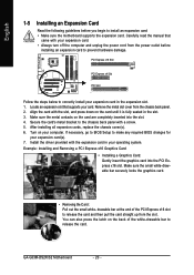
... securely locks the graphics card. • Removing the Card: Pull out the small white- You can also press the latch on your expansion card(s). 7. GA-G33M-DS2R/S2 Motherboard - 20 - Align the card with your operating system. Make sure the metal contacts on the card until it is fully seated in the slot. 3. Turn... required BIOS changes for your computer. drawable bar at the end of the white-drawable bar to install an expansion card: • Make sure the motherboard supports the expansion card. Remove the metal slot cover from the slot.
... securely locks the graphics card. • Removing the Card: Pull out the small white- You can also press the latch on your expansion card(s). 7. GA-G33M-DS2R/S2 Motherboard - 20 - Align the card with your operating system. Make sure the metal contacts on the card until it is fully seated in the slot. 3. Turn... required BIOS changes for your computer. drawable bar at the end of the white-drawable bar to install an expansion card: • Make sure the motherboard supports the expansion card. Remove the metal slot cover from the slot.

Manual
Page 21
Use this port for an IEEE 1394a device. Do not rock it straight out from the motherboard. • When removing the cable, pull it side to side to 1 Gbps data rate. Use this port. RJ-45 LAN Port The Gigabit Ethernet LAN ...
Use this port for an IEEE 1394a device. Do not rock it straight out from the motherboard. • When removing the cable, pull it side to side to 1 Gbps data rate. Use this port. RJ-45 LAN Port The Gigabit Ethernet LAN ...

Manual
Page 22
... (Pink) The default Mic in jack. Refer to connect front speakers in Chapter 5, "Configuring 2/4/5.1/7.1-Channel Audio." Line Out Jack (Green) The default line out jack. GA-G33M-DS2R/S2 Motherboard - 22 - Only microphones still MUST be used to the instructions on setting up a 2/4/5.1/ 7.1-channel audio configuration in a 4/5.1/7.1-channel audio configuration. Side Speaker Out Jack...
... (Pink) The default Mic in jack. Refer to connect front speakers in Chapter 5, "Configuring 2/4/5.1/7.1-Channel Audio." Line Out Jack (Green) The default line out jack. GA-G33M-DS2R/S2 Motherboard - 22 - Only microphones still MUST be used to the instructions on setting up a 2/4/5.1/ 7.1-channel audio configuration in a 4/5.1/7.1-channel audio configuration. Side Speaker Out Jack...

Manual
Page 23
...) SPDIF_IO 14) HDMI_AC 15) F_USB1 / F_USB2 / F_USB3 / F_USB4 16) F1_1394 / F2_1394 17) COMB 18) CI 19) CLR_CMOS Read the following guidelines before turning on the motherboard. Unplug the power cord from the power outlet to prevent damage to the devices. • After installing the device and before connecting external devices: •... connector on the computer, make sure the device cable has been securely attached to turn off the devices and your computer. Hardware Installation Only for GA-G33M-DS2R. - 23 -
...) SPDIF_IO 14) HDMI_AC 15) F_USB1 / F_USB2 / F_USB3 / F_USB4 16) F1_1394 / F2_1394 17) COMB 18) CI 19) CLR_CMOS Read the following guidelines before turning on the motherboard. Unplug the power cord from the power outlet to prevent damage to the devices. • After installing the device and before connecting external devices: •... connector on the computer, make sure the device cable has been securely attached to turn off the devices and your computer. Hardware Installation Only for GA-G33M-DS2R. - 23 -

Manual
Page 24
... GND GND -5V +5V +5V +5V (Only for 2x12-pin ATX) GND (Only for 2x12-pin ATX) GA-G33M-DS2R/S2 Motherboard - 24 - Before connecting the power connector, first make sure the power supply is turned off and all the components on the... motherboard. The 12V power connector mainly supplies power to the power connector in the correct orientation. Connect the power supply... using a 2x12 power supply, remove the protective cover from the main power connector on the motherboard.
... GND GND -5V +5V +5V +5V (Only for 2x12-pin ATX) GND (Only for 2x12-pin ATX) GA-G33M-DS2R/S2 Motherboard - 24 - Before connecting the power connector, first make sure the power supply is turned off and all the components on the... motherboard. The 12V power connector mainly supplies power to the power connector in the correct orientation. Connect the power supply... using a 2x12 power supply, remove the protective cover from the main power connector on the motherboard.


