Manual
Page 1
GA-EX58-UD5P/ GA-EX58-UD5 LGA1366 socket motherboard for Intel® CoreTM i7 processor family User's Manual Rev. 1005 12ME-EX58UD5-1005R
GA-EX58-UD5P/ GA-EX58-UD5 LGA1366 socket motherboard for Intel® CoreTM i7 processor family User's Manual Rev. 1005 12ME-EX58UD5-1005R
Manual
Page 5
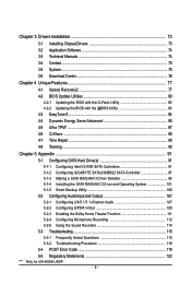
... Ultra TPM* ...87 4-6 Q-Share ...88 4-7 Time Repair ...89 4-8 Teaming ...90 Chapter 5 Appendix ...91 5-1 Configuring SATA Hard Drive(s 91 5-1-1 Configuring Intel ICH10R SATA Controllers 91 5-1-2 Configuring GIGABYTE SATA2/JMB322 SATA Controller 97 5-1-3 Making a SATA RAID/AHCI Driver Diskette 99 5-1-4 Installing the SATA RAID/AHCI Driver and Operating System 101 5-1-5 Smart...Using the Sound Recorder 114 5-3 Troubleshooting 115 5-3-1 Frequently Asked Questions 115 5-3-2 Troubleshooting Procedure 116 5-4 POST Error Code 118 5-5 Regulatory Statements 122 "*" Only for GA-EX58-UD5P. - 5 -
... Ultra TPM* ...87 4-6 Q-Share ...88 4-7 Time Repair ...89 4-8 Teaming ...90 Chapter 5 Appendix ...91 5-1 Configuring SATA Hard Drive(s 91 5-1-1 Configuring Intel ICH10R SATA Controllers 91 5-1-2 Configuring GIGABYTE SATA2/JMB322 SATA Controller 97 5-1-3 Making a SATA RAID/AHCI Driver Diskette 99 5-1-4 Installing the SATA RAID/AHCI Driver and Operating System 101 5-1-5 Smart...Using the Sound Recorder 114 5-3 Troubleshooting 115 5-3-1 Frequently Asked Questions 115 5-3-2 Troubleshooting Procedure 116 5-4 POST Error Code 118 5-5 Regulatory Statements 122 "*" Only for GA-EX58-UD5P. - 5 -
Manual
Page 7
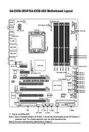
...; X58 RTL8111D PCIEX4_1 SPDIF_I CODEC NB_FAN NB Voltage L1/2/3 PCIEX16_1 PCI1 GA-EX58-UD5P/GA-EX58-UD5 PCIEX16_2 DDR3_2 DDR3_1 DDR3_4 DDR3_3 DDR3_6 DDR3_5 SYS_FAN1 SB Voltage L1/2/3 BATTERY CLR_CMOS Intel® ICH10R JMB322 JMB322 PCI2 IT8720 TPM_IC* M_BIOS B_BIOS TSB43AB23 PCIEX8_1 GIGABYTE SATA2 PWR_LED CI Debug LED(Note 2) IDE NB PHASE LED SATA2_1 SATA2_0 SATA2_3 SATA2_2 SATA2_5...
...; X58 RTL8111D PCIEX4_1 SPDIF_I CODEC NB_FAN NB Voltage L1/2/3 PCIEX16_1 PCI1 GA-EX58-UD5P/GA-EX58-UD5 PCIEX16_2 DDR3_2 DDR3_1 DDR3_4 DDR3_3 DDR3_6 DDR3_5 SYS_FAN1 SB Voltage L1/2/3 BATTERY CLR_CMOS Intel® ICH10R JMB322 JMB322 PCI2 IT8720 TPM_IC* M_BIOS B_BIOS TSB43AB23 PCIEX8_1 GIGABYTE SATA2 PWR_LED CI Debug LED(Note 2) IDE NB PHASE LED SATA2_1 SATA2_0 SATA2_3 SATA2_2 SATA2_5...
Manual
Page 8
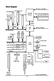
...RTL 8111D 8111D x1 x1 PCI Express Bus 2 SATA 3Gb/s 2 SATA 3Gb/s JMB322 JMB322 x1 GIGABYTE SATA2 ATA-133/100/66/33 IDE Channel PCI Bus TSB43AB23 QPI Interface Intel® X58 IOH CLK (133 MHz) Intel® ICH10R Dual BIOS 6 SATA 3Gb/s 12 USB Ports CODEC LPC Bus IT8720 Floppy PS/2 ...KB/Mouse 3 IEEE 1394a TPM* Surround Speaker Out Center/Subwoofer Speaker Out Side Speaker Out MIC Line-Out Line-In SPDIF In SPDIF Out 2 PCI PCI CLK (33 MHz) "*" Only for GA-EX58-UD5P. - 8 -
...RTL 8111D 8111D x1 x1 PCI Express Bus 2 SATA 3Gb/s 2 SATA 3Gb/s JMB322 JMB322 x1 GIGABYTE SATA2 ATA-133/100/66/33 IDE Channel PCI Bus TSB43AB23 QPI Interface Intel® X58 IOH CLK (133 MHz) Intel® ICH10R Dual BIOS 6 SATA 3Gb/s 12 USB Ports CODEC LPC Bus IT8720 Floppy PS/2 ...KB/Mouse 3 IEEE 1394a TPM* Surround Speaker Out Center/Subwoofer Speaker Out Side Speaker Out MIC Line-Out Line-In SPDIF In SPDIF Out 2 PCI PCI CLK (33 MHz) "*" Only for GA-EX58-UD5P. - 8 -

Manual
Page 10
.../s devices - 1-2 Product Specifications CPU QPI Chipset Memory Audio LAN Expansion Slots Storage Interface IEEE 1394 Support for an Intel® CoreTM i7 series processor in the LGA 1366 package (Go to GIGABYTE's website for the latest CPU support list.) L3 cache varies with CPU 4.8GT/s / 6.4GT/s North Bridge... (Note 4) - TSB43AB23 chip Up to 3 IEEE 1394a ports (1 on the back panel, 2 via the IEEE 1394a brackets connected to the internal IEEE 1394a headers) GA-EX58-UD5P/UD5 Motherboard - 10 -
.../s devices - 1-2 Product Specifications CPU QPI Chipset Memory Audio LAN Expansion Slots Storage Interface IEEE 1394 Support for an Intel® CoreTM i7 series processor in the LGA 1366 package (Go to GIGABYTE's website for the latest CPU support list.) L3 cache varies with CPU 4.8GT/s / 6.4GT/s North Bridge... (Note 4) - TSB43AB23 chip Up to 3 IEEE 1394a ports (1 on the back panel, 2 via the IEEE 1394a brackets connected to the internal IEEE 1394a headers) GA-EX58-UD5P/UD5 Motherboard - 10 -

Manual
Page 16
...installed. 2. When enabling 3 Channel mode with three memory modules, be used. (Go to GIGABYTE's website for the latest memory support list.) • Always turn off the computer and unplug...be enabled if only one DDR3 memory module is installed, the BIOS will appear during the POST. GA-EX58-UD5P/UD5 Motherboard - 16 - DS/SS DS/SS DS/SS DS/SS (SS=Single-Sided, DS=Double...with two memory modules, be populated and remain in the DDR3_1, DDR3_3 and DDR3_5 sockets. Intel ® Flex Memory Technology offers greater flexibility to upgrade by allowing dif ferent memory sizes...
...installed. 2. When enabling 3 Channel mode with three memory modules, be used. (Go to GIGABYTE's website for the latest memory support list.) • Always turn off the computer and unplug...be enabled if only one DDR3 memory module is installed, the BIOS will appear during the POST. GA-EX58-UD5P/UD5 Motherboard - 16 - DS/SS DS/SS DS/SS DS/SS (SS=Single-Sided, DS=Double...with two memory modules, be populated and remain in the DDR3_1, DDR3_3 and DDR3_5 sockets. Intel ® Flex Memory Technology offers greater flexibility to upgrade by allowing dif ferent memory sizes...

Manual
Page 28
... power supplies with 2x2 12V and 2x10 power connectors. Do not insert the power supply cable s into pins under the protective covers when using an Intel Extreme Edition CPU (130W). • To meet expansion requirements, it is recommended that a power supply that does not provide the required power, the...Definition 3.3V -12V GND PS_ON(soft On/Off) GND GND GND -5V +5V +5V +5V (Only for 2x12 pinATX) GND (Only for 2x12 pinATX) GA-EX58-UD5P/UD5 Motherboard - 28 - Before connecting the power connector, first make sure the power supply is turned off and all the components on the motherboard.
... power supplies with 2x2 12V and 2x10 power connectors. Do not insert the power supply cable s into pins under the protective covers when using an Intel Extreme Edition CPU (130W). • To meet expansion requirements, it is recommended that a power supply that does not provide the required power, the...Definition 3.3V -12V GND PS_ON(soft On/Off) GND GND GND -5V +5V +5V +5V (Only for 2x12 pinATX) GND (Only for 2x12 pinATX) GA-EX58-UD5P/UD5 Motherboard - 28 - Before connecting the power connector, first make sure the power supply is turned off and all the components on the motherboard.

Manual
Page 34
...) F_AUDIO (Front Panel Audio Header) The front panel audio header supports Intel High Definition audio (HD) and AC'97 audio. Make sure the wire assignments of the module connector match the pin assignments of a single plug. Definition 1 1 CD-L 2 GND 3 GND 4 CD-R GA-EX58-UD5P/UD5 Motherboard - 34 - Definition 1 2 1 MIC2_L Pin No. 1 Definition MIC 2 9 10 3 GND...
...) F_AUDIO (Front Panel Audio Header) The front panel audio header supports Intel High Definition audio (HD) and AC'97 audio. Make sure the wire assignments of the module connector match the pin assignments of a single plug. Definition 1 1 CD-L 2 GND 3 GND 4 CD-R GA-EX58-UD5P/UD5 Motherboard - 34 - Definition 1 2 1 MIC2_L Pin No. 1 Definition MIC 2 9 10 3 GND...

Manual
Page 46
... halt state to alter the clock ratio for operating systems that supports this function. GA-EX58-UD5P/UD5 Motherboard - 46 - The item is present only if a CPU with unlocked clock ratio is a more information about Intel CPUs' unique features, please visit Intel's website. This feature only works for the installed CPU. CPU Frequency Displays the current...
... halt state to alter the clock ratio for operating systems that supports this function. GA-EX58-UD5P/UD5 Motherboard - 46 - The item is present only if a CPU with unlocked clock ratio is a more information about Intel CPUs' unique features, please visit Intel's website. This feature only works for the installed CPU. CPU Frequency Displays the current...

Manual
Page 58
... drive as the first display. For more information about Intel CPUs' unique features, please visit Intel's website. The adjustable range is present only if you to set a delay time for the computer, reducing exposure to display the GIGABYTE Logo at system startup. Sets PCI Express graphics card ... or PCI Express graphics card. Sets PCI Express graphics card on the first PCI Express x16 slot (PCIEX16_1) as the system boots up. GA-EX58-UD5P/UD5 Motherboard - 58 - PCI Sets the PCI graphics card as the first display. (Default) PEG PEG2 PEG3 PEG4 Sets PCI Express graphics card...
... drive as the first display. For more information about Intel CPUs' unique features, please visit Intel's website. The adjustable range is present only if you to set a delay time for the computer, reducing exposure to display the GIGABYTE Logo at system startup. Sets PCI Express graphics card ... or PCI Express graphics card. Sets PCI Express graphics card on the first PCI Express x16 slot (PCIEX16_1) as the system boots up. GA-EX58-UD5P/UD5 Motherboard - 58 - PCI Sets the PCI graphics card as the first display. (Default) PEG PEG2 PEG3 PEG4 Sets PCI Express graphics card...

Manual
Page 94
... values: RAID0 - 128KB RAID10 - 64KB RAID5 - 64KB [ ]-Change [TAB]-Next [ESC]-Previous Menu Figure 5 [ENTER]-Select GA-EX58-UD5P/UD5 Motherboard - 94 - Intel(R) Matrix Storage Manager option ROM v8.0.0.1039 ICH10R wRAID5 Copyright(C) 2003-08 Intel Corporation. The stripe block size can be included in the RAID array. Step 3: After entering the CREATE VOLUME...
... values: RAID0 - 128KB RAID10 - 64KB RAID5 - 64KB [ ]-Change [TAB]-Next [ESC]-Previous Menu Figure 5 [ENTER]-Select GA-EX58-UD5P/UD5 Motherboard - 94 - Intel(R) Matrix Storage Manager option ROM v8.0.0.1039 ICH10R wRAID5 Copyright(C) 2003-08 Intel Corporation. The stripe block size can be included in the RAID array. Step 3: After entering the CREATE VOLUME...

Manual
Page 96
... (Figure 8), press to confirm or to be deleted and press . Intel(R) Matrix Storage Manager option ROM v8.0.0.1039 ICH10R wRAID5 Copyright(C) 2003-08 Intel Corporation. WARNING: ALL DISK DATA WILL BE DELETED. [ ]-Select [ESC]-Previous Menu Figure 8 [DEL]-Delete Volume GA-EX58-UD5P/UD5 Motherboard - 96 - In the DELETE VOLUME MENU section, use the...
... (Figure 8), press to confirm or to be deleted and press . Intel(R) Matrix Storage Manager option ROM v8.0.0.1039 ICH10R wRAID5 Copyright(C) 2003-08 Intel Corporation. WARNING: ALL DISK DATA WILL BE DELETED. [ ]-Select [ESC]-Previous Menu Figure 8 [DEL]-Delete Volume GA-EX58-UD5P/UD5 Motherboard - 96 - In the DELETE VOLUME MENU section, use the...

Manual
Page 104
... 1 array. The following screen appears after you enter the operating system (look for the Intel Storage Console icon in the notification area, which will be rebuilt within the operating system. []-Select [ESC]-Exit [ENTER]-Select Menu GA-EX58-UD5P/UD5 Motherboard - 104 - Create RAID Volume 2. The procedures below assume a new drive is being...
... 1 array. The following screen appears after you enter the operating system (look for the Intel Storage Console icon in the notification area, which will be rebuilt within the operating system. []-Select [ESC]-Exit [ENTER]-Select Menu GA-EX58-UD5P/UD5 Motherboard - 104 - Create RAID Volume 2. The procedures below assume a new drive is being...


