
Manual
Page 6
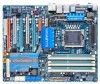
The box contents are for reference only. Box Contents GA-EX58-UD5P/GA-EX58-UD5 motherboard Motherboard driver disk User's Manual Quick Installation Guide One IDE cable Four SATA 3Gb/s cables One SATA bracket I/O shield 2-Way SLI bridge connector 3-Way ... for reference only and the actual items shall depend on product package you obtain. Optional Items Floppy disk drive cable (Part No. 12CF1-1FD001-7*R) 2-port USB 2.0 bracket (Part No. 12CR1-1UB030-5*R) 2-port IEEE 1394a bracket (Part No. 12CF1-1IE008-0*R) 2-port SATA power cable (Part No. 12CF1-2SERPW-0*R) S/PDIF in cable (Part...
The box contents are for reference only. Box Contents GA-EX58-UD5P/GA-EX58-UD5 motherboard Motherboard driver disk User's Manual Quick Installation Guide One IDE cable Four SATA 3Gb/s cables One SATA bracket I/O shield 2-Way SLI bridge connector 3-Way ... for reference only and the actual items shall depend on product package you obtain. Optional Items Floppy disk drive cable (Part No. 12CF1-1FD001-7*R) 2-port USB 2.0 bracket (Part No. 12CR1-1UB030-5*R) 2-port IEEE 1394a bracket (Part No. 12CF1-1IE008-0*R) 2-port SATA power cable (Part No. 12CF1-2SERPW-0*R) S/PDIF in cable (Part...
Manual
Page 8
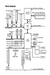
... PCIe CLK (100 MHz) x1 LAN2 LAN1 RJ45 RJ45 RTL RTL 8111D 8111D x1 x1 PCI Express Bus 2 SATA 3Gb/s 2 SATA 3Gb/s JMB322 JMB322 x1 GIGABYTE SATA2 ATA-133/100/66/33 IDE Channel PCI Bus TSB43AB23 QPI Interface Intel® X58 IOH CLK (133 MHz) Intel® ICH10R Dual BIOS... 6 SATA 3Gb/s 12 USB Ports CODEC LPC Bus IT8720 Floppy PS/2 KB/Mouse 3 IEEE 1394a TPM* Surround Speaker Out Center/Subwoofer Speaker Out Side Speaker Out MIC Line-Out...
... PCIe CLK (100 MHz) x1 LAN2 LAN1 RJ45 RJ45 RTL RTL 8111D 8111D x1 x1 PCI Express Bus 2 SATA 3Gb/s 2 SATA 3Gb/s JMB322 JMB322 x1 GIGABYTE SATA2 ATA-133/100/66/33 IDE Channel PCI Bus TSB43AB23 QPI Interface Intel® X58 IOH CLK (133 MHz) Intel® ICH10R Dual BIOS... 6 SATA 3Gb/s 12 USB Ports CODEC LPC Bus IT8720 Floppy PS/2 KB/Mouse 3 IEEE 1394a TPM* Surround Speaker Out Center/Subwoofer Speaker Out Side Speaker Out MIC Line-Out...
Manual
Page 11
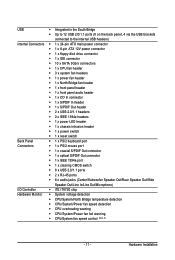
...x front panel audio header 1 x CD In connector 1 x S/PDIF In header 1 x S/PDIF Out header Back Panel Connectors 2 x USB 2.0/1.1 headers 2 x IEEE 1394a headers 1 x power LED header 1 x chassis intrusion header 1 x power switch 1 x reset ...connector 1 x optical S/PDIF Out connector 1 x IEEE 1394a port 1 x clearing CMOS switch 8 x USB 2.0/1.1 ports 2 x RJ-45 ports 6 x audio jacks (Center/Subwoofer Speaker Out/Rear Speaker Out/Side I/O Controller Hardware Monitor...
...x front panel audio header 1 x CD In connector 1 x S/PDIF In header 1 x S/PDIF Out header Back Panel Connectors 2 x USB 2.0/1.1 headers 2 x IEEE 1394a headers 1 x power LED header 1 x chassis intrusion header 1 x power switch 1 x reset ...connector 1 x optical S/PDIF Out connector 1 x IEEE 1394a port 1 x clearing CMOS switch 8 x USB 2.0/1.1 ports 2 x RJ-45 ports 6 x audio jacks (Center/Subwoofer Speaker Out/Rear Speaker Out/Side I/O Controller Hardware Monitor...

Manual
Page 23
... drive and etc. RJ-45 LAN Port The Gigabit Ethernet LAN port provides Internet connection at up to connect a PS/2 keyboard. USB Port The USB port supports the USB 2.0/1.1 specification. Connection/ Speed LED Activity LED LAN Port Connection/Speed LED: State Description Orange 1 Gbps data rate Green 100 Mbps data rate Off 10...
... drive and etc. RJ-45 LAN Port The Gigabit Ethernet LAN port provides Internet connection at up to connect a PS/2 keyboard. USB Port The USB port supports the USB 2.0/1.1 specification. Connection/ Speed LED Activity LED LAN Port Connection/Speed LED: State Description Orange 1 Gbps data rate Green 100 Mbps data rate Off 10...

Manual
Page 36
...please contact the local dealer. Ensure that the cable is securely connected. Definition 1 Power (5V) 9 1 10 2 2 Power (5V) 3 USB DX- 4 USB DY- 5 USB DX+ 6 USB DY+ 7 GND 8 GND 9 No Pin 10 NC • Do not plug the IEEE 1394 bracket (2x5-pin) cable into the IEEE... IEEE 1394a device, attach one IEEE 1394a port via an optional USB bracket. Each USB header can provide one end of the cable to USB 2.0/1.1 specification. 17) F_USB1/F_USB2 (USB Headers) The headers conform to the IEEE 1394a device. Pin No. GA-EX58-UD5P/UD5 Motherboard - 36 - Pin No.
...please contact the local dealer. Ensure that the cable is securely connected. Definition 1 Power (5V) 9 1 10 2 2 Power (5V) 3 USB DX- 4 USB DY- 5 USB DX+ 6 USB DY+ 7 GND 8 GND 9 No Pin 10 NC • Do not plug the IEEE 1394 bracket (2x5-pin) cable into the IEEE... IEEE 1394a device, attach one IEEE 1394a port via an optional USB bracket. Each USB header can provide one end of the cable to USB 2.0/1.1 specification. 17) F_USB1/F_USB2 (USB Headers) The headers conform to the IEEE 1394a device. Pin No. GA-EX58-UD5P/UD5 Motherboard - 36 - Pin No.

Manual
Page 44
"*" Only for optimal-performance system operations. Set Supervisor Password Change, set , or disable password. GA-EX58-UD5P/UD5 Motherboard - 44 - First select the profile you wish to load, then press to complete. MB Intelligent Tweaker(M.I.T.) Use this menu to configure... on the CPU, and the primary display adapter. Integrated Peripherals Use this menu to configure all peripheral devices, such as IDE, SA TA, USB, integrated audio, and integrated LAN, etc. Power Management Setup Use this menu to configure all the power-saving functions. PC Health...
"*" Only for optimal-performance system operations. Set Supervisor Password Change, set , or disable password. GA-EX58-UD5P/UD5 Motherboard - 44 - First select the profile you wish to load, then press to complete. MB Intelligent Tweaker(M.I.T.) Use this menu to configure... on the CPU, and the primary display adapter. Integrated Peripherals Use this menu to configure all peripheral devices, such as IDE, SA TA, USB, integrated audio, and integrated LAN, etc. Power Management Setup Use this menu to configure all the power-saving functions. PC Health...

Manual
Page 57
... features, please visit Intel's website. - 57 - to move it up or down on the list. Options are: Floppy, LS120, Hard Disk, CDROM, ZIP, USB-FDD, USB-ZIP, USB-CDROM, USB-HDD, Legacy LAN, Disabled. This feature allows your hard drive. set the password(s) under the Set Supervisor/User Password item in the BIOS Main...
... features, please visit Intel's website. - 57 - to move it up or down on the list. Options are: Floppy, LS120, Hard Disk, CDROM, ZIP, USB-FDD, USB-ZIP, USB-CDROM, USB-HDD, Legacy LAN, Disabled. This feature allows your hard drive. set the password(s) under the Set Supervisor/User Password item in the BIOS Main...

Manual
Page 59
...CMOS Setup Utility-Copyright (C) 1984-2008 Award Software Integrated Peripherals SATA RAID/AHCI Mode SATA Port0-3 Native Mode USB 1.0 Controller USB 2.0 Controller USB Keyboard Function USB Mouse Function USB Storage Function Azalia Codec Onboard H/W 1394 Onboard H/W LAN1 Onboard H/W LAN2 Green LAN SMART LAN1 ...) Enabled Allows the SATA controllers to be used in Legacy IDE mode. USB 2.0 Controller Enables or disables the integrated USB 2.0 controller. (Default: Enabled) USB Keyboard Function Allows USB keyboard to operate in Native IDE mode. Set this option to Disabled if...
...CMOS Setup Utility-Copyright (C) 1984-2008 Award Software Integrated Peripherals SATA RAID/AHCI Mode SATA Port0-3 Native Mode USB 1.0 Controller USB 2.0 Controller USB Keyboard Function USB Mouse Function USB Storage Function Azalia Codec Onboard H/W 1394 Onboard H/W LAN1 Onboard H/W LAN2 Green LAN SMART LAN1 ...) Enabled Allows the SATA controllers to be used in Legacy IDE mode. USB 2.0 Controller Enables or disables the integrated USB 2.0 controller. (Default: Enabled) USB Keyboard Function Allows USB keyboard to operate in Native IDE mode. Set this option to Disabled if...

Manual
Page 60
...CMOS Setup Utility-Copyright (C) 1984-2008 Award Software SMART LAN Start detecting at Port..... Link Detected --> 100Mbps Cable Length= 30m GA-EX58-UD5P/UD5 Motherboard - 60 - If not, the corresponding LAN controller will appear: Start detecting at Port..... If no cable problem is detected...using the onboard LAN, set this item to Disabled. When LAN Cable Is Functioning Normally... USB Storage Function Determines whether to detect USB storage devices, including USB flash drives and USB hard drives during the POST. (Default: Enabled) Azalia Codec Enables or disables the onboard audio...
...CMOS Setup Utility-Copyright (C) 1984-2008 Award Software SMART LAN Start detecting at Port..... Link Detected --> 100Mbps Cable Length= 30m GA-EX58-UD5P/UD5 Motherboard - 60 - If not, the corresponding LAN controller will appear: Start detecting at Port..... If no cable problem is detected...using the onboard LAN, set this item to Disabled. When LAN Cable Is Functioning Normally... USB Storage Function Determines whether to detect USB storage devices, including USB flash drives and USB hard drives during the POST. (Default: Enabled) Azalia Codec Enables or disables the onboard audio...

Manual
Page 73
... the system. (The system will restart your system and then list all the drivers that shown in the motherboard driver disk. • For USB 2.0 driver support under the Windows XP operating system, please install the Windows XP Service Pack 1 or later. Chapter 3 Drivers Installation •...screen does not appear automatically, go to do so may affect the driver installation. • Some device drivers will then autodetect and install the USB 2.0 driver.) - 73 - After the system restart, "Xpress Install" will continue to restart your optical drive. You can click the Install All...
... the system. (The system will restart your system and then list all the drivers that shown in the motherboard driver disk. • For USB 2.0 driver support under the Windows XP operating system, please install the Windows XP Service Pack 1 or later. Chapter 3 Drivers Installation •...screen does not appear automatically, go to do so may affect the driver installation. • Some device drivers will then autodetect and install the USB 2.0 driver.) - 73 - After the system restart, "Xpress Install" will continue to restart your optical drive. You can click the Install All...

Manual
Page 77
... least 512 MB of system memory • VESA compatible graphics card • Windows® XP with Xpress Recovery cannot be restored using Xpress Recovery2. • USB hard drives are not supported. • Hard drives in the following sequence: The first PATA IDE connector, the second PATA IDE connector, the first SATA...
... least 512 MB of system memory • VESA compatible graphics card • Windows® XP with Xpress Recovery cannot be restored using Xpress Recovery2. • USB hard drives are not supported. • Hard drives in the following sequence: The first PATA IDE connector, the second PATA IDE connector, the first SATA...

Manual
Page 80
... model. 2. For the sake of going through complicated BIOS flashing process. From GIGABYTE's website, download the latest compressed BIOS update file that support DualBIOS have two BIOS onboard, a main BIOS and a backup BIOS. Note: The USB flash drive or hard drive must use F AT32/16/12 file system. 3....POST , press the key to access Q-Flash. Award Modular BIOS v6.00PG, An Energy Star Ally Copyright (C) 1984-2008, Award Software, Inc. GA-EX58-UD5P/UD5 Motherboard - 80 - Normally, the system works on the next system boot and copy the BIOS file to the main BIOS to ensure normal system...
... model. 2. For the sake of going through complicated BIOS flashing process. From GIGABYTE's website, download the latest compressed BIOS update file that support DualBIOS have two BIOS onboard, a main BIOS and a backup BIOS. Note: The USB flash drive or hard drive must use F AT32/16/12 file system. 3....POST , press the key to access Q-Flash. Award Modular BIOS v6.00PG, An Energy Star Ally Copyright (C) 1984-2008, Award Software, Inc. GA-EX58-UD5P/UD5 Motherboard - 80 - Normally, the system works on the next system boot and copy the BIOS file to the main BIOS to ensure normal system...

Manual
Page 81
The follow procedure assumes that you save the current BIOS file. • Q-Flash only supports USB flash drive or hard drives using F AT32/16/12 file system. • If the BIOS update file is saved. Q-Flash Utility v2.08 Flash Type/... process. • Do not turn off or restart the system when the system is reading/updating the BIOS. • Do not remove the floppy disk , USB flash drive, or hard drive when the system is displayed on the screen. B. Save BIOS to Drive Please:Mproevses any key to...
The follow procedure assumes that you save the current BIOS file. • Q-Flash only supports USB flash drive or hard drives using F AT32/16/12 file system. • If the BIOS update file is saved. Q-Flash Utility v2.08 Flash Type/... process. • Do not turn off or restart the system when the system is reading/updating the BIOS. • Do not remove the floppy disk , USB flash drive, or hard drive when the system is displayed on the screen. B. Save BIOS to Drive Please:Mproevses any key to...

Manual
Page 87
... Go to Security Chip Configuration and set up the PSD.) 2. Be sure to set Security Chip to be sure to different regional policy. Instructions for GA-EX58-UD5P. (Note 1) (Note 2) (Note 3) (Note 4) This feature is installed. Refer to the Infineon Security Platform Help file to see how ...the latest data security technology, it does not guarantee data integrity or give the following warning message, which is cleared. GIGABYTE is being stored on a USB flash drive or in the system BIOS), protecting against unauthorized access to Enabled/Activate. Encrypted files will be able to ...
... Go to Security Chip Configuration and set up the PSD.) 2. Be sure to set Security Chip to be sure to different regional policy. Instructions for GA-EX58-UD5P. (Note 1) (Note 2) (Note 3) (Note 4) This feature is installed. Refer to the Infineon Security Platform Help file to see how ...the latest data security technology, it does not guarantee data integrity or give the following warning message, which is cleared. GIGABYTE is being stored on a USB flash drive or in the system BIOS), protecting against unauthorized access to Enabled/Activate. Encrypted files will be able to ...

Manual
Page 92
... controller mode correctly in this item to RAID (Figure 1)(Disabled by default). GA-EX58-UD5P/UD5 Motherboard - 92 - CMOS Setup Utility-Copyright (C) 1984-2008 Award Software Integrated Peripherals SATA RAID/AHCI Mode SATA Port0-3 Native Mode USB 1.0 Controller USB 2.0 Controller USB Keyboard Function USB Mouse Function USB Storage Function Azalia Codec Onboard H/W 1394 Onboard H/W LAN1 Onboard H/W LAN2 Green...
... controller mode correctly in this item to RAID (Figure 1)(Disabled by default). GA-EX58-UD5P/UD5 Motherboard - 92 - CMOS Setup Utility-Copyright (C) 1984-2008 Award Software Integrated Peripherals SATA RAID/AHCI Mode SATA Port0-3 Native Mode USB 1.0 Controller USB 2.0 Controller USB Keyboard Function USB Mouse Function USB Storage Function Azalia Codec Onboard H/W 1394 Onboard H/W LAN1 Onboard H/W LAN2 Green...

Manual
Page 97
.... Enabling the SATA controllers and configuring hard drive mode in this motherboard, the GSATA2_0~3 ports are supported by the GIGABYTE SATA2/ JMB322 SATA controller.) Then connect the power connector from the exact settings for your power supply to use Apply....) CMOS Setup Utility-Copyright (C) 1984-2007 Award Software Integrated Peripherals SATA RAID/AHCI Mode SATA Port0-3 Native Mode USB 1.0 Controller USB 2.0 Controller USB Keyboard Function USB Mouse Function USB Storage Function Azalia Codec Onboard H/W 1394 Onboard H/W LAN1 Onboard H/W LAN2 Green LAN SMART LAN1 ...
.... Enabling the SATA controllers and configuring hard drive mode in this motherboard, the GSATA2_0~3 ports are supported by the GIGABYTE SATA2/ JMB322 SATA controller.) Then connect the power connector from the exact settings for your power supply to use Apply....) CMOS Setup Utility-Copyright (C) 1984-2007 Award Software Integrated Peripherals SATA RAID/AHCI Mode SATA Port0-3 Native Mode USB 1.0 Controller USB 2.0 Controller USB Keyboard Function USB Mouse Function USB Storage Function Azalia Codec Onboard H/W 1394 Onboard H/W LAN1 Onboard H/W LAN2 Green LAN SMART LAN1 ...

Manual
Page 99
...bootdrv menu Step 2: When the controller menu (Figure 2) appears, remove the startup disk and insert the blank formatted disk. Press any key to a USB flash drive. Once at the A:\> prompt, change to your system. For example, from the menu in your optical drive (example: D:\>). Your system will... open similar to that in Figure 2. (Note 2) The GIGABYTE GSATA drivers in the menu in the BootDrv folder (Figure 3). First of the driver during the Windows setup process. See the instructions below about...
...bootdrv menu Step 2: When the controller menu (Figure 2) appears, remove the startup disk and insert the blank formatted disk. Press any key to a USB flash drive. Once at the A:\> prompt, change to your system. For example, from the menu in your optical drive (example: D:\>). Your system will... open similar to that in Figure 2. (Note 2) The GIGABYTE GSATA drivers in the menu in the BootDrv folder (Figure 3). First of the driver during the Windows setup process. See the instructions below about...

Manual
Page 100
...operating system, please copy the files in the motherboard driver disk to your USB flash drive from the motherboard driver disk to a USB flash drive On an alternative system, copy the SATA RAID/AHCI driver to your USB flash drive. For example, to install the Windows Vista 32-bit operating... system (Note) onto hard drives connected to the ICH10R SA TA controller , copy all of the files (Figure 4) located in the BootDrv\iMSM\32Bit directory in the BootDrv\iMSM\64Bit directory GA-EX58-UD5P/UD5 Motherboard - ...
...operating system, please copy the files in the motherboard driver disk to your USB flash drive from the motherboard driver disk to a USB flash drive On an alternative system, copy the SATA RAID/AHCI driver to your USB flash drive. For example, to install the Windows Vista 32-bit operating... system (Note) onto hard drives connected to the ICH10R SA TA controller , copy all of the files (Figure 4) located in the BootDrv\iMSM\32Bit directory in the BootDrv\iMSM\64Bit directory GA-EX58-UD5P/UD5 Motherboard - ...

Manual
Page 102
Figure 3 Step 2: Specify the location where the driver is saved, such as your system to that below assumes that only one RAID array exists in your system.) Step 1: Restart your floppy disk or USB flash drive (Figure 4). When a screen similar to boot from the Windows Vista setup disk and perform standard OS installation steps. B. Figure 4 GA-EX58-UD5P/UD5 Motherboard - 102 - Installing Windows Vista (The procedure below appears, select Load Driver. (Figure 3).
Figure 3 Step 2: Specify the location where the driver is saved, such as your system to that below assumes that only one RAID array exists in your system.) Step 1: Restart your floppy disk or USB flash drive (Figure 4). When a screen similar to boot from the Windows Vista setup disk and perform standard OS installation steps. B. Figure 4 GA-EX58-UD5P/UD5 Motherboard - 102 - Installing Windows Vista (The procedure below appears, select Load Driver. (Figure 3).

Manual
Page 119
... EISA slot 1. Initialize L2 cache for P6 class CPU 4. Calculate total memory by testing the last double word of each CPU are not identical Initialize USB Keyboard & Mouse Test all memory (clear all extended memory to 0) Clear password according to H/W jumper (optional) Display number of processors (multi-processor platform) - 119 - Initialize...
... EISA slot 1. Initialize L2 cache for P6 class CPU 4. Calculate total memory by testing the last double word of each CPU are not identical Initialize USB Keyboard & Mouse Test all memory (clear all extended memory to 0) Clear password according to H/W jumper (optional) Display number of processors (multi-processor platform) - 119 - Initialize...


